Code
Building
Code Requirements for Structural Concrete (ACI 318-14) and Commentary (ACI
318R-14)
Minimum
Design Loads for Buildings and Other Structures (ASCE/SEI 7-10)
International
Code Council, 2012 International Building Code, Washington, D.C., 2012
References
Notes on
ACI 318-11 Building Code Requirements for Structural Concrete, Twelfth Edition,
2013 Portland Cement Association.
Concrete
Floor Systems (Guide to Estimating and Economizing), Second Edition, 2002 David
A. Fanella
Simplified
Design of Reinforced Concrete Buildings, Fourth Edition, 2011 Mahmoud E. Kamara
and Lawrence C. Novak
Design Data
Floor-to-Floor
Height = 12 ft (provided by architectural drawings)
wc
= 150 pcf
fc’
= 5,000 psi
fy = 60,000 psi (For flexural reinforcement)
fyt = 60,000 psi (For shear and torsional reinforcement)
Superimposed dead load, SDL = 20 psf framed
partitions, wood studs plaster 2 sides
ASCE/SEI 7-10 (Table C3-1)
Typical
Floor Level, Live load, Lo = 80 psf (Office
building) ASCE/SEI 7-10 (Table
4-1)
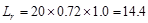
Roof Live
Load, Lo = 20 psf (Ordinary flat
roofs) ASCE/SEI
7-10 (Table 4-1)
Required
fire resistance rating = 2 hours
Solution
In this example
deflection will be calculated and checked to satisfy project deflection limits.
Minimum member thickness and depths from ACI 318-14 will be used for
preliminary sizing.
a. One-way Slab
Using minimum thickness for solid one-way slabs in Table
7.3.1.1 for the solid slab spanning between the ribs.
End Spans:  in
ACI 318-14 (Table 7.3.1.1)
in
ACI 318-14 (Table 7.3.1.1)
Interior Spans:  in
ACI 318-14 (Table 7.3.1.1)
in
ACI 318-14 (Table 7.3.1.1)
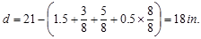
The minimum slab thickness for wide-module
joists for 2-hour fire rating is 4.6 in.
IBC 2012 (Table
720.1(3))
Therefore, select a slab thickness of 5 in. for all spans.
b. One-way Joist
The wide-module joist systems do not meet
the limitations of ACI 318-14, 9.8.1.1 through 9.8.1.4.
Therefore, the structural members of this type of joist construction shall be
designed with standard provisions for slabs and beams.
ACI 318-14 (9.8.1.8)
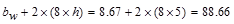
Using minimum thickness for
non-prestressed beams in Table 9.3.1.1. For the ribs (part
of the joists) supporting the solid slab.
End Span:  in
(governs) ACI 318-14 (Table
9.3.1.1)
in
(governs) ACI 318-14 (Table
9.3.1.1)
Interior Span:  in
ACI 318-14 (Table 9.3.1.1)
in
ACI 318-14 (Table 9.3.1.1)
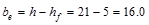
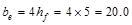
Therefore, select rib depth of 16 in. for a total
joist depth of 21 in.
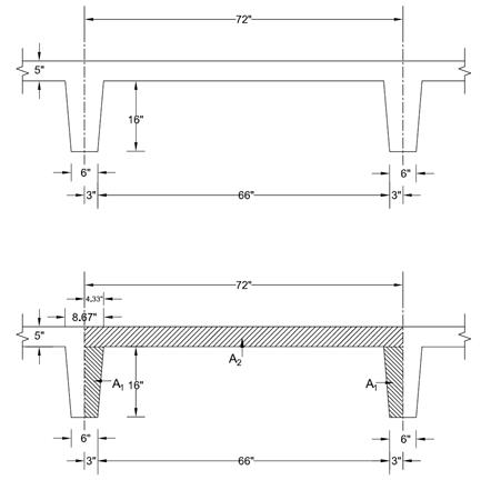
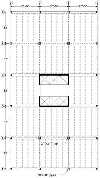
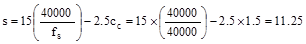
Figure 2 – Slab
and Joist Dimensions
a.
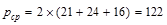
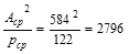
Interior Columns
Select a preliminary size based on
the axial load demand. Determine interior column loads as follows:
The governing load combination:  ACI
318-14 (Eq. 5.3.1b)
ACI
318-14 (Eq. 5.3.1b)
Where:
D = Dead Load; L= Live Load; Lr=
Roof Live Load
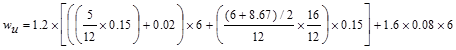
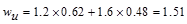
Typical Floor Level Loads
# of Floors = 4
Dead Loads, D
Self-weight
of wide-module joist system (see Figure 2):
Joist average
thickness = 
Weight of the
joist = 0.5524 x 150 pcf = 82.83 psf.
Superimposed dead load = 20 psf
Live Load, L:
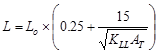
Calculate the live load reduction per ASCE/SEI 7-10
 ASCE/SEI
7-10 (Eq. 4-1)
ASCE/SEI
7-10 (Eq. 4-1)
Where:
L = reduced design live load per ft2
of area supported by the member
Lo = unreduced design live load per ft2
of area supported by the member = 80 psf
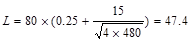
KLL = live load element
factor ASCE/SEI
7-10 (Table 4-2)
AT = tributary area  ft2
ft2
 psf
psf
Which
satisfies  requirement for members supporting two or more floors.
ASCE/SEI 7-10 (4.7.2)
Roof Level Loads
Dead Loads, D
Self-weight
of wide-module joist system (see Figure 2):
Joist average
thickness = 
Weight of the
joist = 0.5524 x 150 pcf = 82.83 psf.
No
superimposed dead load at the roof
Roof Live
Load, Lr: Calculate the roof live load reduction
 ;
;
 ASCE/SEI
7-10 (Eq 4-2)
ASCE/SEI
7-10 (Eq 4-2)
Where:
 psf
psf
 since
since
 ft2
ft2
 ft2
ft2
 for
flat roof
for
flat roof
 psf
psf
Total Factored Load on 1st
story interior column (@ 1st interior support)
Total Floor Load 
 kips
kips
Total Roof Load lb
lb kips
kips
Assume 24 in square column with 4 – #
11 vertical bars with design axial strength,  of
of
 ACI 318-14 (22.4.2)
 lb
lb
 kips
kips
Column Self-weight  kips
kips
Total Reaction @ 1st
interior support  kips
kips
 kips.
kips.
Therefore, the preliminary interior
column size of 24 in. x 24 in. is adequate.
b.
Edge (Exterior) Columns
Select a preliminary size based on
the axial load demand. Therefore, the load take-down for an edge column is done
as follows:
The governing load combination: ACI
318-14 (Eq. 5.3.1b)
Typical Floor Level Loads
# of Floors = 4
Dead Loads, D
Self-weight
of wide-module joist system (see Figure 2):
Weight of the
joist = 82.83 psf.
Superimposed dead load = 20 psf
Live Load, L:
Calculate the live load reduction per ASCE/SEI 7-10
 ASCE/SEI 7-10 (Eq. 4-1)
Where:
L = reduced design live load per ft2
of area supported by the member
Lo = unreduced design live load per ft2
of area supported by the member = 80 psf
KLL = live load element factor =
4 ASCE/SEI
7-10 (Table 4-2)
AT = tributary area 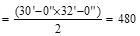 ft2
ft2
 psf
psf
Which
satisfies requirement for members supporting two or more floors.
ASCE/SEI 7-10 (4.7.2)
Roof Level Loads
Dead Loads, D
Weight of the
joist = 82.83 psf.
No
superimposed dead load at the roof
Roof Live
Load, Lr: Calculate the roof live load reduction
;
ASCE/SEI
7-10 (Eq 4-2)
Where:
psf
 ,
since 200 ft2 < At = 480 ft2
< 600 ft2
,
since 200 ft2 < At = 480 ft2
< 600 ft2
for
flat roof
 psf
psf
Total Factored Load on 1st
story edge column (@ 1st interior support)
Total Floor Load 
 kips
kips
Total Roof Load lb
lb kips
kips
Assume 20 in square column with 4 – #
11 vertical bars with design axial strength, of
ACI 318-14 (22.4.2)
 lb
lb
 kips
kips
Column Self-weight 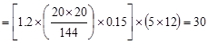 kips
kips
Total Reaction @ 1st
interior support 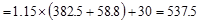 kips
kips
 kips.
kips.
Therefore, the preliminary edge
column size of 20 in. x 20 in. is adequate.
c.
Corner Columns
Select a preliminary size based on
the axial load demand. Therefore, the load take-down for a corner column is
done as follows:
The governing load combination: ACI
318-14 (Eq. 5.3.1b)
Typical Floor Level Loads
# of Floors = 4
Dead Loads, D
Self-weight
of wide-module joist system (see Figure 2):
Weight of the
joist = 82.83 psf.
Superimposed dead load = 20 psf
Live Load, L:
Calculate the live load reduction per ASCE/SEI 7-10
ASCE/SEI 7-10 (Eq. 4-1)
Where:
L = reduced design live load per ft2
of area supported by the member
Lo = unreduced design live load per ft2
of area supported by the member = 80 psf
KLL = live load element factor =
4 ASCE/SEI
7-10 (Table 4-2)
AT = tributary area 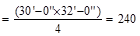 ft2
ft2
 psf
psf
Which
satisfies requirement for members supporting two or more floors.
ASCE/SEI 7-10 (4.7.2)
Roof Level Loads
Dead Loads, D
Weight of the
joist = 82.83 psf.
No
superimposed dead load at the roof
Roof Live
Load, Lr: Calculate the roof live load reduction
 ;
;  ASCE/SEI
7-10 (Eq 4-2)
ASCE/SEI
7-10 (Eq 4-2)
Where:
psf
 ,
since 200 ft2 < At = 240 ft2
< 600 ft2
,
since 200 ft2 < At = 240 ft2
< 600 ft2
for
flat roof
 psf
psf
Total Factored Load on 1st
story corner column (@ exterior support)
Total Floor Load 
 kips
kips
Total Roof Load lb
lb kips
kips
Assume 20 in square column with 4 – #
11 vertical bars with design axial strength, of
ACI 318-14 (22.4.2)
lb
kips
Column Self-weight kips
Total Reaction @ exterior support  kips
kips.
kips
kips.
Therefore, the preliminary edge
column size of 20 in. x 20 in. is adequate.
The design of the
following structural members is performed and compared with results of the
engineering software program spBeam:
2.1. One-Way Slab
2.2. One-Way Joist
2.3. Interior Beam
2.4. Exterior Beam
2.5. Interior Column
A unit strip of
1 ft is considered for the design of slab spanning between ribs. Note that ACI
318-14 does not allow live load reduction for one-way slabs.
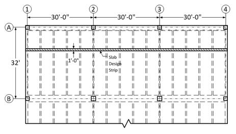
Figure
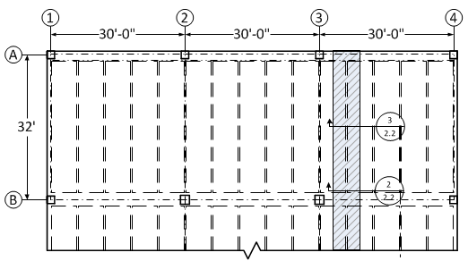
2.1 – Partial plan view illustrating slab design strip
Slab design
involves the following steps:
2.1.1. Determination of span loads
2.1.2. Determination of design moments and shears
2.1.3. Flexural Design
2.1.4. Shear Design
2.1.5. Deflections
2.1.6. Computer Program Solution
2.1.7. Summary and comparison of design results
2.1.8. Conclusions and observations
The
following gravity load combinations are considered:
 ACI 318-14 (Eq. 5.3.1a)
 kips/ft
per ft
kips/ft
per ft
 ACI 318-14 (Eq. 5.3.1b)
 kips/ft
per ft
kips/ft
per ft
Span loads are governed by the
second load combination.
The factored moment and shear can
be determined using the simplified method if the requirements are
satisfied: ACI
318-14 (6.5.1)
ü Members are prismatic.
ü Loads are uniformly distributed.
ü L ≤ 3D (0.08 kips/ft per ft ≤
3 x 0.0825 kips/ft per ft)
ü There are at least two spans.
ü The longer of two adjacent spans does
not exceed the shorter by more than 20 percent.
Thus, the approximate coefficients
can be used. The factored moments and shears are determined and summarized in
the following tables. ACI
318-14 (Table 6.5.2 and Table 6.5.3)
|
Table 2.1.2.1
– One-Way Slab Design Moment Values
|
|
Location
|
Design Moment
Value
|
|
End Spans
|
Exterior Support Negative
|
 ft-kips/ft ft-kips/ft
|
|
Mid-span
|
 ft-kips/ft ft-kips/ft
|
|
Interior Support Negative
|
 ft-kips/ft ft-kips/ft
|
|
Interior Spans
|
Mid-span Positive
|
 ft-kips/ft ft-kips/ft
|
|
Support Negative
|
 ft-kips/ft ft-kips/ft
|
|
Table 2.1.2.2
– One-Way Slab Design Shear Values
|
|
Location
|
Design Shear
Value
|
|
End Span at Face of First Interior
Support
|
 kips/ft kips/ft
|
|
At Face of all other Supports
|
 kips/ft kips/ft
|
For the one-way slab of a wide-module joist system, a
single layer of longitudinal reinforcement is provided. The first interior
support negative moment governs the design as tabulated in Table 2.1.2.1.
Therefore, it is favorable to place the single layer reinforcement closer to
the top fiber of the concrete slab. The required reinforcement shall be
calculated for the first interior support negative moment first. The required
reinforcement for the end span positive moment shall also be calculated as the
low effective depth due to the reinforcement location may govern the required
reinforcement amount. Finally, the required reinforcement for design shall be
checked against the minimum shrinkage and temperature reinforcement requirement
per ACI 318-14 (24.4.3.2).
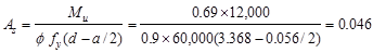
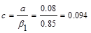
Calculate
the required reinforcement to resist the first interior support negative
moment:
 ft-kips/ft
Use welded wire fabric reinforcement, 6 x 6-W5.5 x
W5.5 with 1.5 in. concrete cover. The distance from extreme compression fiber
to the centroid of longitudinal tension reinforcement, d, is calculated
below:
 in.
in.
To determine the area of steel,
assumptions have to be made whether the section is tension or compression
controlled, and regarding the distance between the resultant compression and
tension forces along the slab section (jd). In this example,
tension-controlled section will be assumed so the reduction factor is
equal to 0.9, and jd will be taken equal to 0.95d. The
assumptions will be verified once the area of steel is finalized.
is
equal to 0.9, and jd will be taken equal to 0.95d. The
assumptions will be verified once the area of steel is finalized.
Assume in.
in.
Unit
strip width, b = 12 in.
 in.2/ft
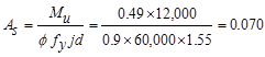
Recalculate
‘a’ for the actual As = 1.31 in.2:  in.
in.
 in.
in.

Therefore,
the assumption that section is tension-controlled is valid.
 in.2/ft
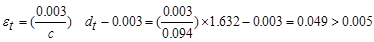
Calculate
the required reinforcement to resist the positive moment:
 ft-kips/ft
The
distance from extreme compression fiber to the centroid of longitudinal tension
reinforcement:
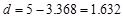 in.
in.
To determine the area of steel,
assumptions have to be made whether the section is tension or compression
controlled, and regarding the distance between the resultant compression and
tension forces along the slab section (jd). In this example,
tension-controlled section will be assumed so the reduction factoris
equal to 0.9, and jd will be taken equal to 0.95d. The
assumptions will be verified once the area of steel is finalized.
Assume in.
in.
Unit
strip width, b = 12 in.
 in.2/ft
Recalculate
‘a’ for the actual As = 0.070 in.2:  in.
in.
 in.
in.
Therefore,
the assumption that section is tension-controlled is valid.
 in.2/ft
Check
the shrinkage and temperature reinforcement requirement:
 in.2
/ ft ACI 318-14 (Table 24.4.3.2)
in.2
/ ft ACI 318-14 (Table 24.4.3.2)
Check
reinforcement spacing for crack control:
The
maximum spacing of the flexural reinforcement closest to the tension face of
the slab shall be:
 ,
but not greater than
,
but not greater than  ACI
318-14 (Table 24.3.2)
ACI
318-14 (Table 24.3.2)
Where:
 Maximum
reinforcement spacing for crack control, in
Maximum
reinforcement spacing for crack control, in
 Calculated
stress in reinforcement closest to the tension face at service load, ksi
Calculated
stress in reinforcement closest to the tension face at service load, ksi
 The
least distance from surface of reinforcement to the tension face, in
The
least distance from surface of reinforcement to the tension face, in
 psi
ACI 318-14 (24.3.2.1)
psi
ACI 318-14 (24.3.2.1)
 in.
for reinforcement resisting negative moment at supports (i.e. tension at the
top)
in.
for reinforcement resisting negative moment at supports (i.e. tension at the
top)
 in.
for reinforcement resisting positive moment at mid-span (i.e. tension at the
bottom)
in.
for reinforcement resisting positive moment at mid-span (i.e. tension at the
bottom)
Thus,
At
supports
 in
(governs @ support)
in
(governs @ support)
But not greater than  in.
in.
At
mid-span
 in
(governs @ mid-span)
in
(governs @ mid-span)
But not greater than in.
Therefore, for this one-way slab, the shrinkage and
temperature reinforcement requirement per ACI 318-14 (Table
24.4.3.2) governs the required
reinforcement area ( in2/ft)
and crack control requirement per ACI 318-14 (Table 24.3.2)
governs the reinforcement spacing (
in2/ft)
and crack control requirement per ACI 318-14 (Table 24.3.2)
governs the reinforcement spacing ( in.).
in.).
The most feasible reinforcement solution that meets
both requirements mentioned above is to provide welded wire fabric
reinforcement, 6 x 6-W5.5 x W5.5. Note that the welded wire reinforcement
selected provides minimum shrinkage and temperature reinforcement in the slab
direction parallel to the joists as well. Alternately, deformed bars can be
utilized in lieu of welded wire fabric. It should be noted that two conditions
specific to this design contribute to having such a stringent spacing
requirement.
These are listed below:
- The 5 in. slab
has a single layer reinforcement that is placed near the top surface (i.e.
clear cover from the top surface to the reinforcement is 1.5 in. This result in
a high cc value for the calculation of reinforcement spacing for
crack control due to positive moment.
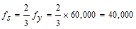
- The stress in
reinforcement closest to the tension face at service load, fs,
is taken as 2/3 fy as permitted by ACI 318-14
without calculation. It is very likely that under the loading considered, the
stress in the steel will be lower than 2/3 fy. The fs
value is expected to be in the range of 1/3 fy to 1/2 fy.
Even if it is assumed to be 1/2 fy , s value will be 12 in.
From Table
2.1.2.2 above, the shear value in end span at face of first interior support
governs.
 kips/ft
The design shear
at a distance, d, away from the face of support,
 kips/ft
Shear strength
provided by concrete
 ACI 318-14 (Eq. 22.5.5.1)
 lb/ft
lb/ft
 kips/ft
 kips/ft
 kips/ft
.
kips/ft
.
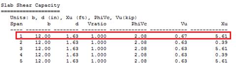
Therefore, the
slab shear capacity is adequate.
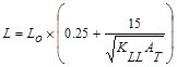
Since the preliminary slab thickness met minimum thickness requirement,
the deflection calculations are not required. Unless governed by fire rating
requirements; as in this example; lesser thicknesses and consequently cost savings
can be achieved through deflection computations. Deflection values are
calculated and provided for every model created by spBeam Program and can be
used by the engineer to make additional optimization decisions.
spBeam Program
can be utilized to analysis and design beams and one-way slab systems. The
one-way slab is modeled as 1-ft unit strip supported on ribs. The ribs provide
some rotational stiffness at the supports. In spBeam solution, the rotational
stiffness is assumed as 32,000* kip-in/rad for modeling the joist
supports. Also, for one-way slab run, the rib widths assumed as 6 in. and
modeled through dummy columns of 6 in. x 12 in. with zero height (i.e. column
stiffness is zero, but the 6 in. dimension of the column is utilized to push
the design moments 3 in. from the support centerline). In this example,
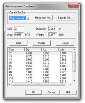
user-defined bar size #2 is defined in spBeam to represent welded wire fabric,
W5.5, with the cross-sectional area of 0.055 in2 (see Fig. 2.1.6.1).
Figure
2.1.6.1 – spBeam Reinforcement Database – User-defined Bar Set
The
program calculates the internal forces (shear force and bending moment), moment
and shear capacities, immediate and long-term deflections, and required
reinforcements. The graphical and text results are provided below for input and
output of the spBeam program. The graphical
and text results are provided here for both input and output of the spBeam model.
* Refer to spBeam manual (Chapter 2 – Special
Considerations for One and Two-Way Joist Systems)
* Refer to spBeam manual (Chapter 4 – Defining Boundary
Conditions, Rotational Stiffness)
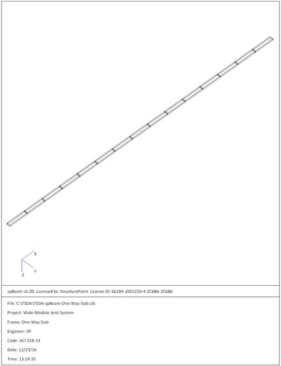
Figure 2.1.6.2 – spBeam Model – Isometric View of 15 Span
– 1ft Wide Unit Strip of One-Way Slab
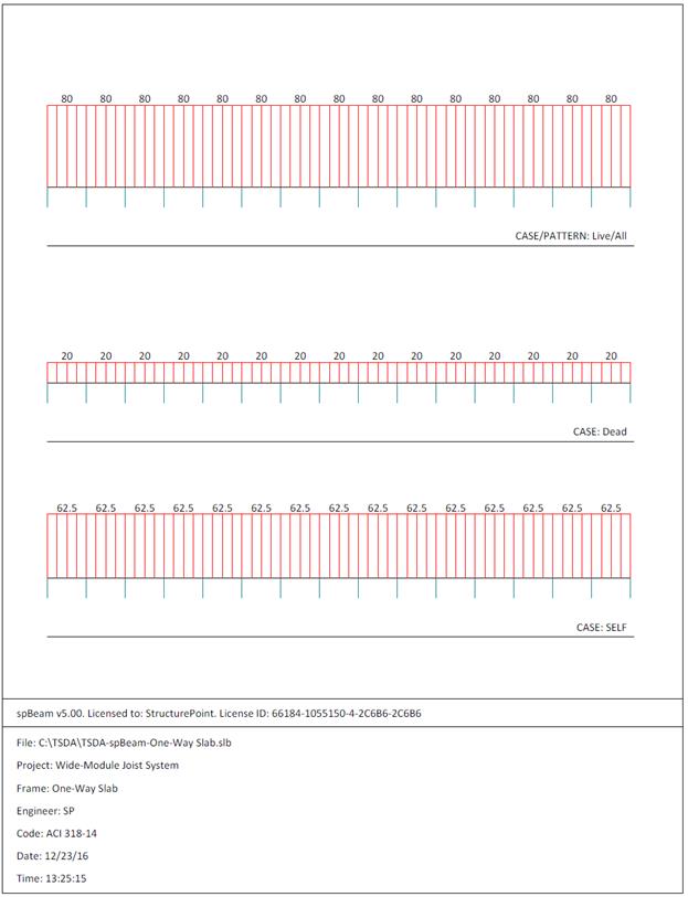
Figure 2.1.6.3 – spBeam Model – Loads (Including Live Load
Patterning) units in lb/ft2
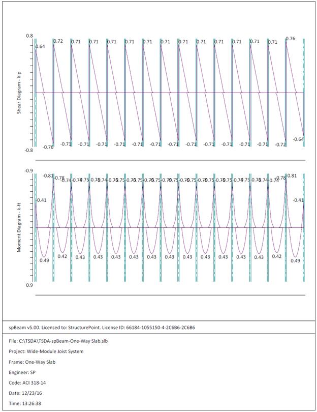
Figure 2.1.6.4 – spBeam Model – Internal Forces (Shear
Force Diagram and Bending Moment Diagram)
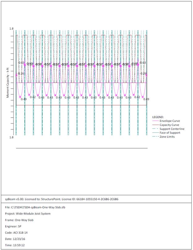
Figure 2.1.6.5 – spBeam Model – Moment Capacity Diagram
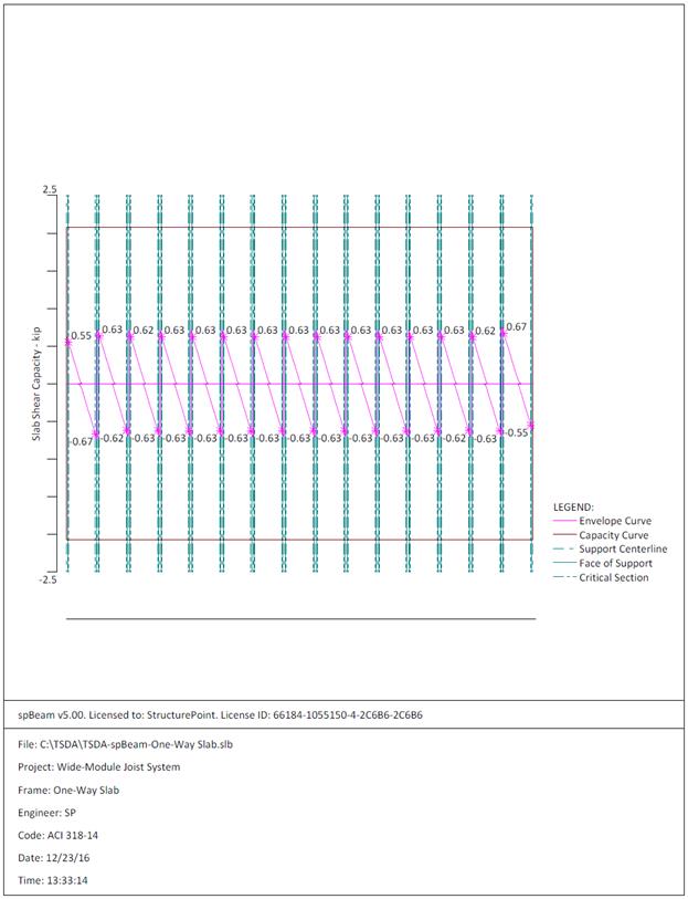
Figure 2.1.6.6 – spBeam Model – Shear Capacity Diagram
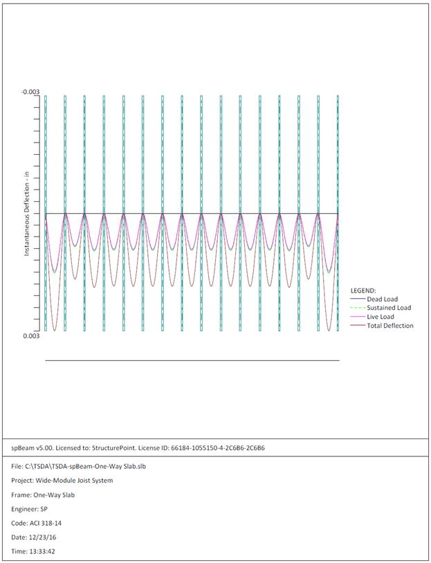
Figure 2.1.6.7 – spBeam Model – Immediate Deflection
Diagram
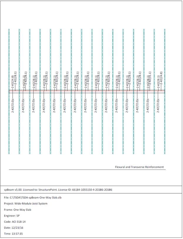
Figure 2.1.6.8 – spBeam Model – Reinforcement Diagram

|
Table 2.1.7.1
– Comparison of Hand Solution with spBeam Solution
|
|
Flexural
Design
|
|
Span
Location
|
Design Moment
(ft-kips/ft)
|
Reinforcement
Required
for Flexure
(in2/ft)
|
Minimum
Reinforcement (in2/ft)
(Shrinkage
& Temperature Reinforcement)
|
|
End Span
|
Hand
Solution
|
spBeam
Solution
|
Hand
Solution
|
spBeam
Solution
|
Hand
Solution
|
spBeam
Solution
|
|
Interior
Negative
|
0.69
|
0.63
|
0.046
|
0.042
|
0.108
(2-#2)
|
0.108
(2-#2)
|
|
Positive
|
0.49
|
0.49
|
0.069
|
0.069
|
0.108
(2-#2)
|
0.108
(2-#2)
|
|
Shear Design
|
|
|
|
Span
Location
|
Vu
(kips/ft)
|
φVn
(kips/ft)
|
|
|
|
End Span
|
Hand
Solution
|
spBeam
Solution
|
Hand
Solution
|
spBeam
Solution
|
|
|
|
Interior
Negative
|
0.69
|
0.67
|
2.15
|
2.08
|
|
|
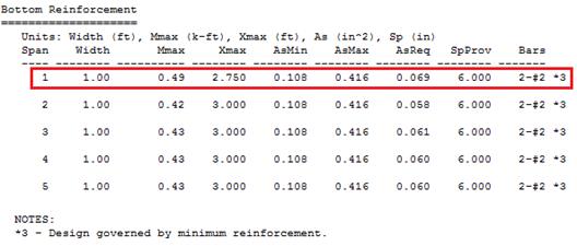
Minimum reinforcement requirement governed flexural design in this
example. spBeam program enables the user to
enter the rotational support springs as boundary conditions for joist supports
and evaluate various analysis and design options beyond the limitations of the
simplified method. The coefficients traditionally used to determine moments do
not address various types of support and geometry.
Typically, in wide-module joist construction, one-way slab is reinforced
with single layer reinforcement placed near the top in the primary direction.
As seen in this example, this may cause crack control criteria to govern the
reinforcement spacing and consequently, it may warrant the use of welded wire
fabric reinforcement instead of deformed bar.
The maximum calculated total immediate (instantaneous) deflection (DL +
LL) = 0.003 in., this value can be compared with maximum permissible calculated
deflection limitation per project criteria in accordance to ACI 318-14.
ACI 318-14 (Table 24.2.2)
In addition to deflection results, parametric studies can be performed in
spBeam to optimize design and detailing
results. Note in the reinforcement diagram (Figure 2.1.6.8) 2-#2 for top
reinforcement in the span left and right zones as well as span bottom
reinforcement. One layer is suitable by inspection (Figure 2.1.6.5) to meet the
required area of steel for top and bottom reinforcement.
The wide-module
joists in this floor are considered as beams per ACI 318-14 (9.8.1.8).
Therefore, the design of the joist shall conform to the requirements of T-beams
per ACI 318-14 (9.2.4).
Figure
2.2 – Partial plan view illustrating one-way joist to be design
Joist design
involves the following steps:
2.2.1. Determination of span loads
2.2.2. Determination of design moments and shears
2.2.3. Flexural Design
2.2.4. Shear Design
2.2.5. Deflections
2.2.6. Computer Program Solution
2.2.7. Summary and comparison of design results
2.2.8. Conclusions and observations
The
following gravity load combinations are considered:
ACI 318-14 (Eq. 5.3.1a)
 kips/ft
ACI 318-14 (Eq. 5.3.1b)
 kips/ft
Span loads are governed by the
second load combination.
Note that for Floor Live Load
Reduction per ASCE/SEI 7-10:
 ASCE/SEI 7-10 (Eq. 4-1)
Where:
Live Load Element Factor,  for
interior beams ASCE/SEI 7-10 (Table
4-2)
for
interior beams ASCE/SEI 7-10 (Table
4-2)
Tributary Area 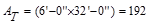 ft2
ft2
Since ft2
ft2  ft2,
live load reduction is not applicable.
ft2,
live load reduction is not applicable.
The factored moment and shear can
be determined using the simplified method if the requirements are
satisfied:
ACI 318-14 (6.5.1)
ü Members are prismatic.
ü Loads are uniformly distributed.
ü L ≤ 3D (0.48 kips/ft ≤ 3
x 0.62 kips/ft)
ü There are at least two spans.
ü The longer of two adjacent spans does
not exceed the shorter by more than 20 percent.
Thus, the approximate coefficients
can be used. The factored moments and shears are determined and summarized in
the following tables. ACI
318-14 (Table 6.5.2 and Table 6.5.3)
|
Table 2.2.2.1
– One-Way Joist Design Moment Values
|
|
Location
|
Design Moment
Value
|
|
End Spans
|
Exterior Support Negative
|
 ft-kips ft-kips
|
|
Mid-span
|
 ft-kips ft-kips
|
|
Interior Support Negative
|
 ft-kips ft-kips
|
|
Interior Spans
|
Mid-span Positive
|
 ft-kips ft-kips
|
|
Support Negative
|
 ft-kips ft-kips
|
|
Table 2.2.2.2
– One-Way Joist Design Shear Values
|
|
Location
|
Design Shear
Value
|
|
End Span at Face of First Interior
Support
|
 kips kips
|
|
At Face of all other Supports
|
 kips kips
|
* When support beam is wider than the
column, the clear span, ln, of the joists is measured from the face of the
column. For calculating negative moments, ln, is taken as the
average of the adjacent clear spans.
ACI
318-14 (6.5.2)
For the one-way joist of a wide-module joist system,
the end span moment values govern the design as tabulated in Table 2.2.2.1.
Calculate
the required reinforcement to resist the first interior support negative
moment:
 ft-kips
Use #5 reinforcement with 1.5 in. concrete cover. The
distance from extreme compression fiber to the centroid of longitudinal tension
reinforcement, d, is calculated below:
 in.
in.
To determine the area of steel,
assumptions have to be made whether the section is tension or compression
controlled, and regarding the distance between the resultant compression and
tension forces along the slab section (jd). In this example,
tension-controlled section will be assumed so the reduction factoris
equal to 0.9, and jd will be taken equal to 0.9d since we are
designing for the negative moment in a T-beam (narrow compression zone). The
assumptions will be verified once the area of steel is finalized.
Assume in.
in.
Joist
average width, 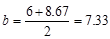 in.
in.
The required reinforcement at initial
trial is calculated as follows:
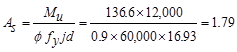 in.2
in.2
Recalculate
‘a’ for the actual As = 1.79 in.2: 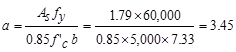 in.
in.
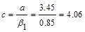 in.
in.
Therefore,
the assumption that section is tension-controlled is valid.
 in.2
in.2
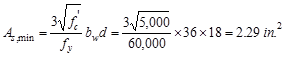
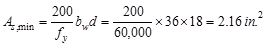
The
minimum reinforcement shall not be less than
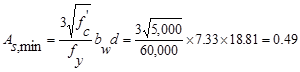 in.2 ACI 318-14 (9.6.1.2(a))
And
not less than
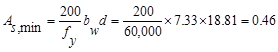 in.2
ACI 318-14 (9.6.1.2(b))
in.2
ACI 318-14 (9.6.1.2(b))
Part of the negative-moment steel
shall be distributed over a width equal to the smaller of the effective flange
width (72 in) and  in.
ACI 318-14 (24.3.4)
in.
ACI 318-14 (24.3.4)
Where the effective width of the
overhanging flange on each side of the beam web is the smallest of the
following:
ACI 318-14 (6.3.2.1)
 in.,
where h is the slab thickness.
in.,
where h is the slab thickness.
 in.,
where sw is the clear distance to the adjacent web.
in.,
where sw is the clear distance to the adjacent web.
 in
in
Therefore, the effective flange
width is 72 in
Provide 6-# 5 bars within 38.4 in
width.
 in2
in2
 in2
o.k.
in2
o.k.
Calculate
the required reinforcement to resist the positive moment:
 ft-kips
In
the positive moment regions, the beam acts as a T-shaped beam. The effective
flange width as was calculated earlier is 72 in.
By assuming #3
bars for joist stirrups and the maximum bar size for joist bottom reinforcement
as #7 and following the 1.5 in. concrete cover to reinforcement requirement of
beam stirrups per ACI 318-14 (20.6.1), the distance from
extreme compression fiber to the centroid of longitudinal tension
reinforcement, d, is calculated below:
 in
in
Since we are
designing for the positive moment in a T-Beam (wide compression zone), select a
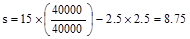
moment arm, jd approximately equal to 0.95d.Assume that  in.
in.
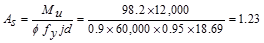 in2
in2
Recalculate
‘a’ for the actual As = 1.23 in.2:  in.
in.
 in.
in.
Therefore,
the assumption that section is tension-controlled is valid.
 in.2
in.2
Use 2-#7 bundled
bars with  in2
>
in2
>  in2
o.k.
in2
o.k.
Figure
2.2.3.1 – Cross-sectional view at joist mid-span (Section 2/2.2 in Figure 2.2)
Figure
2.2.3.2 – Cross-sectional view at joist near support face (Section 3/2.2 in
Figure 2.2)
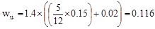
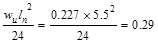
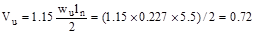
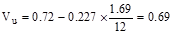
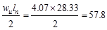
From Table 2.2.2.2 above, the shear
value in end span at face of first interior support governs.
 kips
kips
The design shear at a distance, d,
away from the face of support,
 kips
/ ft
kips
/ ft
Shear strength provided by concrete
 ACI 318-14 (Eq. 22.5.5.1)
 lb
lb
 kips
kips
Since ,
shear reinforcement is required.
,
shear reinforcement is required.
Try # 3, Grade 60 double-leg
stirrups with a 90° hook.
The nominal shear strength required
to be provided by shear reinforcement is
 kips
kips
Check whether Vs
is less than 
If Vs is greater
than,
then the cross-section has to be revised as ACI 318-14
limits the shear capacity to be provided by stirrups to.
ACI 318-14 (22.5.1.2)
 lb
lb
 kips
kips
Since  does
not exceed.
The cross-section is adequate.
does
not exceed.
The cross-section is adequate.
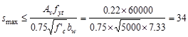
Assume # 3 stirrups with two legs ( in2)
in2)
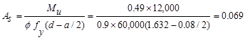
Calculate the required stirrup
spacing as
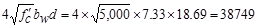
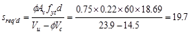 in.
in.
Check whether the required spacing
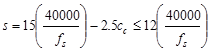
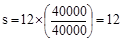
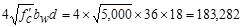
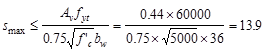
based on the shear demand meets the spacing limits for shear reinforcement per ACI 318-14 (9.7.6.2.2).
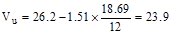
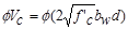
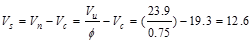
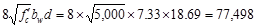
Check whether Vs
is less than
 lb
lb
 kips
> Vs = 12.6 kips
kips
> Vs = 12.6 kips
Therefore, maximum stirrup spacing
shall be the smallest of d/2 and 24 in. ACI 318-14 (Table 9.7.6.2.2)
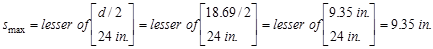
This value governs over the
required stirrup spacing of 19.7 in which was based on the demand.
Joist minimum shear reinforcement
requirements must be checked since wide-module joists do not satisfy ACI
318-14 (9.8).
Check the maximum stirrup spacing
based on minimum shear reinforcement
 in.
(does not govern) ACI 318-14
(10.6.2.2(a))
in.
(does not govern) ACI 318-14
(10.6.2.2(a))
 in.
(does not govern) ACI 318-14 (10.6.2.2(b))
in.
(does not govern) ACI 318-14 (10.6.2.2(b))
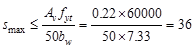
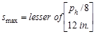
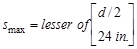
Therefore, smax
value is governed by the spacing limit per ACI 318-14 (9.7.6.2.2),
and is equal to 9.35 in.
Use #3 @ 9 in.
stirrups
 ACI 318-14 (22.5.1.1 and 22.5.10.5.3)
 kips
kips
 kips
>
kips
>  kips
o.k.
kips
o.k.
Compute where  is
equal to
is
equal to ,
and the stirrups can be stopped
,
and the stirrups can be stopped
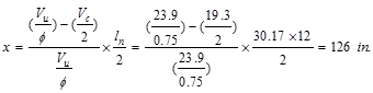
At interior end of the exterior
span, use 16-#3 @ 9 in o.c., Place 1st stirrup 2 in. from the face
of supporting girder.
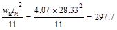
Since the preliminary joist depth met minimum depth requirement, the
deflection calculations are not required. A lesser depth maybe possible and
consequently cost savings can be achieved through deflection computations.
Deflection values are calculated and provided for every model created by spBeam
Program and can be used by the engineer to make additional optimization
decisions.
spBeam
Program can be utilized to analysis and design the one-way wide-module joist. A
single wide-module joist is modeled as a five span continuous-beam.
The program
calculates the internal forces (shear force and bending moment), moment and
shear capacities, immediate and long-term deflection results, and required
flexural reinforcement. The graphical and text results are provided here for
both input and output of the spBeam model.
The ribs are
modeled as a rectangular longitudinal beam with an equivalent width of 7.33 in.
and 21 in. depth to reflect the sloped sides of the forming pans.
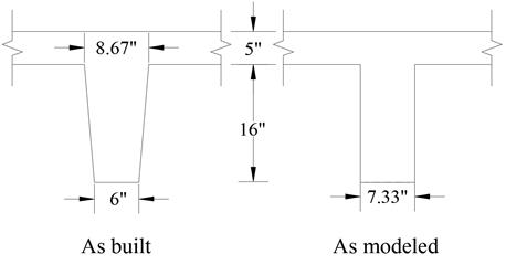
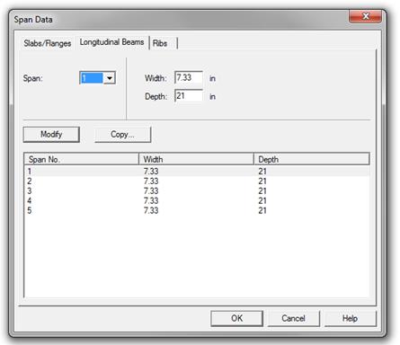
Figure 2.2.6.1 – spBeam Model –One-Way Joist Section
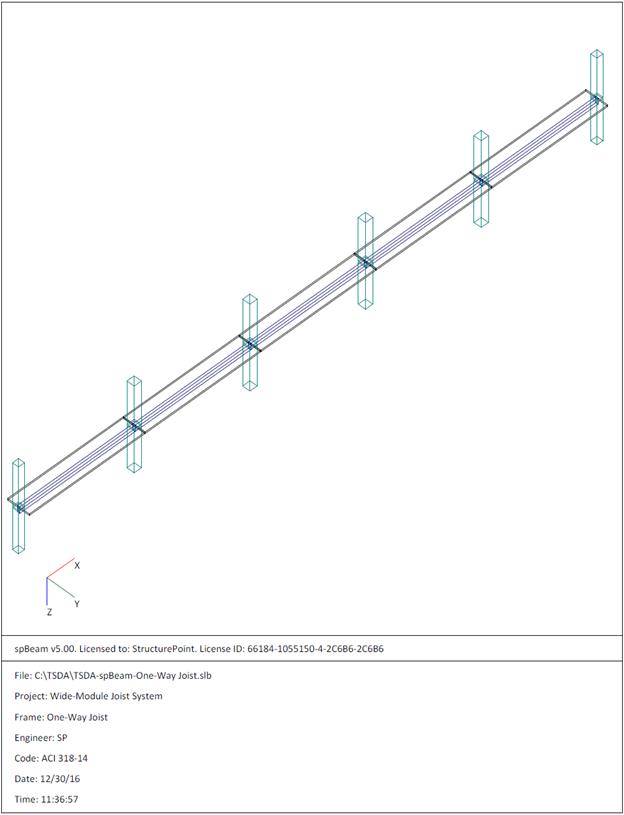
Figure 2.2.6.2 – spBeam Model – Isometric View – One-Way
Joist
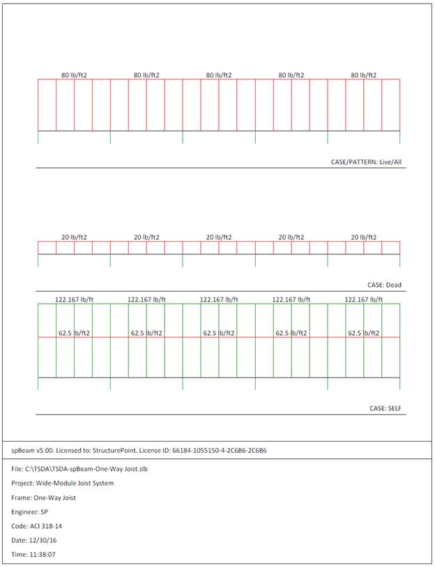
Figure 2.2.6.3 – spBeam Model – Loads (Including Live Load
Patterning)
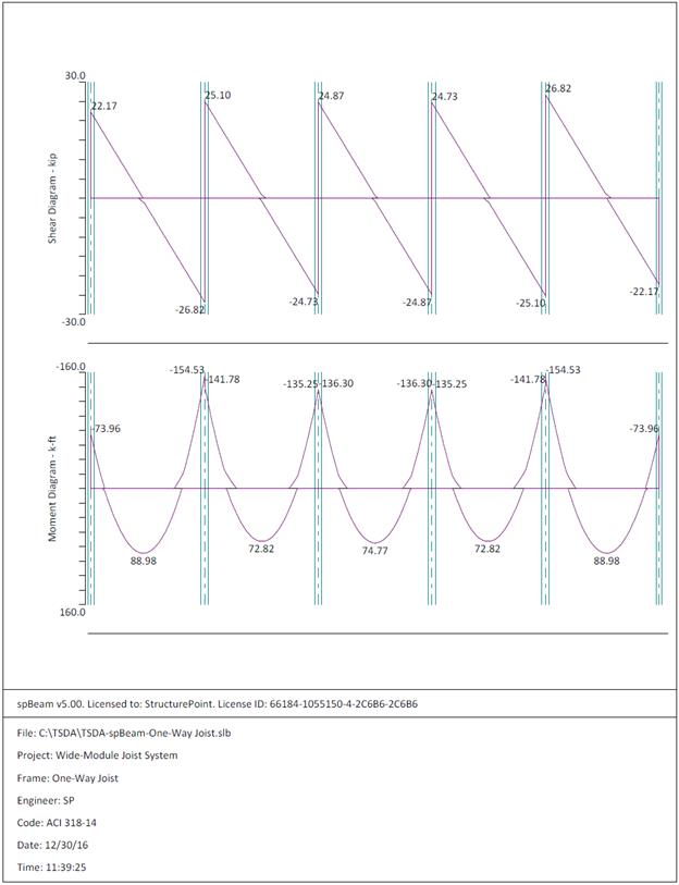
Figure 2.2.6.4 – spBeam Model – Internal Forces (Shear
Force Diagram and Bending Moment Diagram)
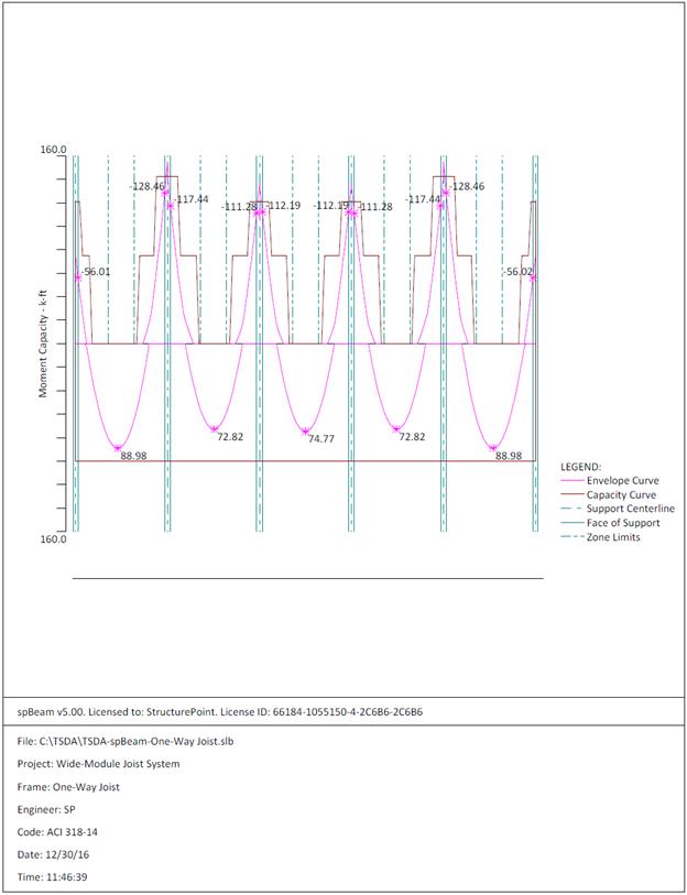
Figure 2.2.6.5 – spBeam Model – Moment Capacity Diagram
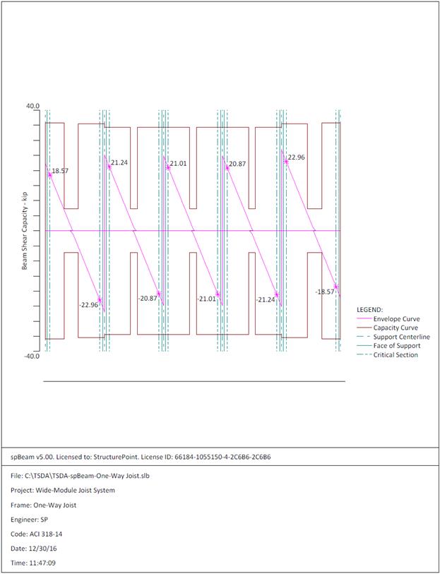
Figure 2.2.6.6 – spBeam Model – Shear Capacity Diagram
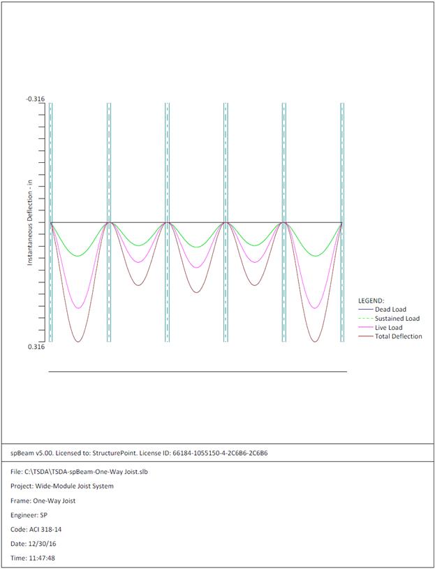
Figure 2.2.6.7 – spBeam Model – Immediate Deflection
Diagram
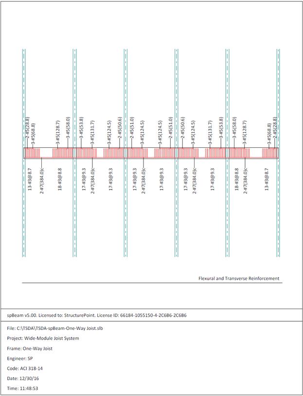
Figure 2.2.6.8 – spBeam Model – Reinforcement Diagram
|
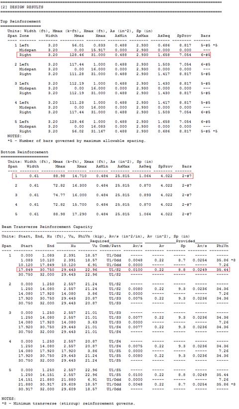
Table 2.2.7.1
– Comparison of Hand Solution with spBeam Solution
|
|
Flexural
Design
|
|
Span
Location
|
Design Moment
(ft-kips)
|
Reinforcement
Required
for Flexure
(in2)
|
Reinforcement
Provided
for Flexure
(in2)
|
|
End Span
|
Hand
Solution
|
spBeam
Solution
|
Hand
Solution
|
spBeam
Solution
|
Hand
Solution
|
spBeam
Solution
|
|
Interior
Negative
|
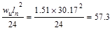
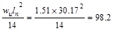
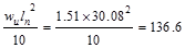
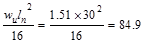
136.6
|
128.46
|
1.78
|
1.658
|
6-#5
|
6-#5
|
|
Positive
|
98.2
|
88.98
|
1.18
|
1.064
|
2-#7
|
2-#7
|
|
Shear Design
|
|
|
|
Span
Location
|
Vu
(kips)
|
φVn
(kips)
|
|
|
|
End Span
|
Hand
Solution
|
spBeam
Solution
|
Hand
Solution
|
spBeam
Solution
|
|
|
|
Interior
Negative
|
23.9
|
22.96
|
35
|
35.44
|
|
|
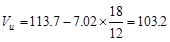
In this design example, the one-way joist system is modeled as a
continuous T-beam representing single one-way joist. There is a good agreement
between the hand solution and computer solution. Note that the coefficients
traditionally used to determine moments do not address various types of support
and geometry.
The maximum calculated total immediate (instantaneous) deflection (DL +
LL) = 0.316 in., this value can be compared with maximum permissible calculated
deflection limitation per project criteria in accordance to ACI 318-14.
ACI 318-14 (Table 24.2.2)
In addition to deflection results,
parametric studies can be performed in spBeam
to optimize design and detailing results. With a minimum spacing of 1 in.
between the 2-#7, two stirrups, and 1.5 in. cover on each side, a total width
of 6.5 in. is required. The rib width at the
bar level is 6.385 in. which is slightly less than required. For detailing
purposes, one of the following options can be used:
1.
Bottom bars can be bundled. This practice is often found in joist construction.
2.
Stirrups can be rotated by a small angle to preserve the minimum spacing.
3. Bottom bars can be raised sufficiently
to achieve the required width taking into the account the reduction into the
moment capacity.
4.
Other detailing options provided by the builder/formwork supply.
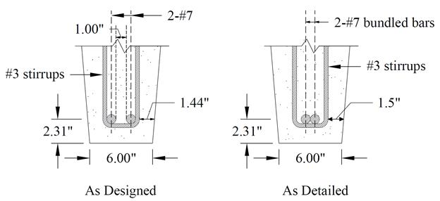
Figure 2.2.8 – Joist Cross-Section
In wide-module joist construction, the supporting beam, sometimes
referred to as girder, depth is typically set to match the overall joist depth.
Therefore, the beam depth is set to 21 in. This depth need to satisfy the minimum
depth requirement of ACI 318-14 (Table
9.3.1.1) so that the deflection computations can be waived.
Using the minimum depth for
non-prestressed beams in Table 9.3.1.1.
End Span:  in
(governs) < 21 in. ACI 318-14 (Table
9.3.1.1)
in
(governs) < 21 in. ACI 318-14 (Table
9.3.1.1)
Interior Span:  in
ACI 318-14 (Table 9.3.1.1)
in
ACI 318-14 (Table 9.3.1.1)
Therefore, the preliminary beam depth satisfies the
minimum depth requirement.

Figure
2.3 – Partial plan view showing interior beam along grid B
Beam (girder)
design involves the following steps:
2.3.1. Determination of span loads
2.3.2. Determination of design moments and shears
2.3.3. Flexural Design
2.3.4. Shear Design
2.3.5. Deflections
2.3.6. Computer Program Solution
2.3.7. Summary and comparison of design results
2.3.8. Conclusions and observations
Dead
Load:
Try 36 in width
for the beam (slightly larger than the column width that helps facilitate the
forming, and reduces the beam longitudinal vs. column vertical bar
interference)
Joist & Slab
Weight  kips/ft
Beam Weight  kips/ft
Superimposed
Dead Load, SDL 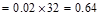 kips/ft
Live
Load:
Check
for live load reduction per ASCE/SEI
7-10
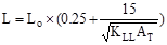 ASCE/SEI 7-10 (Eq. 4-1)
Where:
 reduced
design live load per ft2 of area supported by the member
reduced
design live load per ft2 of area supported by the member
 unreduced
design live load per ft2 of area supported by the member = 80 psf
unreduced
design live load per ft2 of area supported by the member = 80 psf
 live
load element factor = 2 for interior beams ASCE/SEI
7-10 (Table 4-2)
live
load element factor = 2 for interior beams ASCE/SEI
7-10 (Table 4-2)
 tributary
area ft2
tributary
area ft2
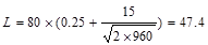 psf
psf
Which
satisfies  requirement for members supporting one floor.
ASCE/SEI 7-10 (4.7.2)
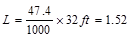 kips/ft
Load
Combination:
The
following gravity load combinations are considered:
ACI 318-14 (Eq. 5.3.1a)
 kips/ft
ACI
318-14 (Eq. 5.3.1b)
 kips/ft
The span loads are governed by the
second load combination.
The factored moment and shear can
be determined using the simplified method if the requirements are
satisfied:
ACI 318-14 (6.5.1)
ü Members are prismatic.
ü Loads are uniformly distributed.
ü L ≤ 3D (1.52 kips/ft ≤
3 x 3.83 kips/ft)
ü There are at least two spans.
ü The longer of two adjacent spans does
not exceed the shorter by more than 20 percent.
Thus, the
approximate coefficients can be used. The factored moment and shear are
determined and summarized in the following tables. ACI
318-14 (Table 6.5.2 and Table 6.5.3)
|
Table 2.3.2.1
– Interior Beam Design Moment Values
|
|
Location
|
Design Moment
Value
|
|
End Spans
|
Exterior Support Negative
|
 ft-kips ft-kips
|
|
Mid-span
|
 ft-kips ft-kips
|
|
Interior Support Negative
|
 ft-kips ft-kips
|
|
Interior Spans
|
Mid-span Positive
|
 ft-kips ft-kips
|
|
Support Negative
|
 ft-kips ft-kips
|
|
Table 2.3.2.2
– Interior Beam Design Shear Values
|
|
Location
|
Design Shear
Value
|
|
End Span at Face of First Interior
Support
|
 kips kips
|
|
At Face of all other Supports
|
 kips kips
|
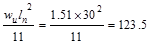
For this interior beam, the end span moment values
govern the design as tabulated in Table 2.3.2.1.
Calculate
the required reinforcement to resist the first interior support negative
moment:
 ft-kips
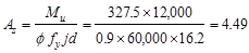
Use #8 bars with 1.5 in. concrete cover per ACI
318-14 (Table 20.6.1.3.1). To avoid interference with joist
negative moment reinforcement, the clear cover to the girder top reinforcement
is required to be increased by lowering the girder top reinforcement. The distance from extreme compression fiber to the
centroid of longitudinal tension reinforcement, d, is calculated below:
 in.
in.
To determine the area of steel,
assumptions have to be made whether the section is tension or compression
controlled, and regarding the distance between the resultant compression and
tension forces along the slab section (jd). In this example, tension-controlled
section will be assumed so the reduction factoris
equal to 0.9, and jd will be taken equal to 0.9d since we are
designing for the negative moment in a rectangular beam (narrow compression
zone). The assumptions will be verified once the area of steel is finalized.
Assume in.
in.
Interior
beam width,  in.
in.
The required reinforcement at initial
trial is calculated as follows:
 in.2
in.2
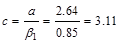
Recalculate
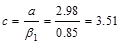
‘a’ for the actual As = 7.59 in.2: 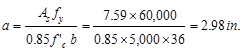
 in.
in.
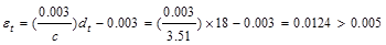
Therefore,
the assumption that section is tension-controlled is valid.
The
minimum reinforcement shall not be less than
 ACI 318-14
(9.6.1.2(a))
ACI 318-14
(9.6.1.2(a))
And
not less than
 ACI 318-14 (9.6.1.2(b))
Provide 10 - # 8 bars:
 in2
in2
 in2
o.k.
in2
o.k.
Maximum spacing allowed:
Check the requirement for
distribution of flexural reinforcement to control flexural cracking:
 ACI 318-14 (Table 24.3.2)
 in.
in.
Use  ksi
ACI
318-14 (24.3.2.1)
ksi
ACI
318-14 (24.3.2.1)
 in.
(governs)
in.
(governs)
 in.
in.
Spacing provided for 10-# 8 bars
 in.
in.
 in.
o.k.
in.
o.k.
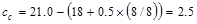
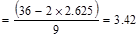
Where ds = 2.625
in. for #3 stirrup as shown in the following Figure. CRSI
2002 (Figure 12-9)
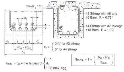
Figure
2.3.3 – Maximum number of bars in beams
Check the spacing, s provided, is
greater than the minimum center to center spacing, smin where
 CRSI 2002 (Figure 12-9)
Where maximum aggregate size is ¾”
Since the spacing provided is
greater than 2 in. Therefore, 10-#8 bars are o.k.
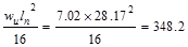
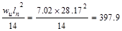
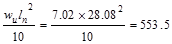
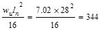
All the values
on Table 2.3.3.1 are calculated based on the procedure outlined above.
|
Table 2.3.3.1
– Reinforcing Design Summary
|
|
|
End Span
|
Interior Span
|
|
|
Exterior
Negative
|
Positive
|
Interior
Negative
|
Positive
|
Negative
|
|
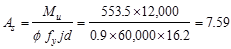
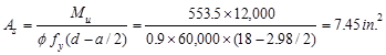
Design Moment, Mu
(ft-kips)
|
348.2
|
397.9
|
553.5
|
344
|
500.3
|
|
Effective depth,
d (in.)
|
18.0*
|
18.625**
|
18*
|
18.625**
|
18*
|
|
As
req’d (in.2)
|
4.53
|
5.03
|
7.45
|
4.31
|
6.68
|
|
As
min (in.2)
|
2.29
|
2.37
|
2.29
|
2.37
|
2.29
|
|
Reinforcement
|
6-#8
|
7-#8
|
10-#8
|
6-#8
|
9-#8
|
|
* The beam top bars are to be placed below the joist top
bars.
|
|
** The beam bottom bars are to be placed at the bottom-most
layer. The joist bottom bars, then, shall be spliced at
joist-beam intersection.
|
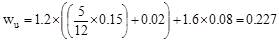
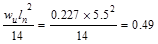
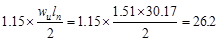
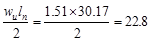
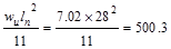
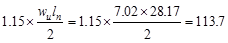
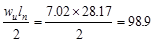
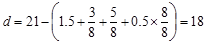
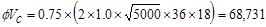
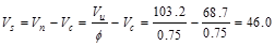
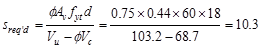
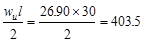
From Table 2.3.2.2 above, the shear
value in end span at face of first interior support governs.
 kips
kips
The design shear at a distance, d,
away from the face of support,
 kips
kips
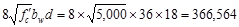
Shear strength provided by concrete
ACI 318-14 (Eq. 22.5.5.1)
 lb
lb
 kips
kips
Since,
shear reinforcement is required.
Try # 3, Grade 60 four-leg stirrups
(Av = 0.44 in.2) with a 90° hook.
The nominal shear strength required
to be provided by shear reinforcement is
 kips
kips
Check whether Vs
is less than
If Vs is greater
than,
then the cross-section has to be revised as ACI 318-14
limits the shear capacity to be provided by stirrups to .
ACI 318-14 (22.5.1.2)
.
ACI 318-14 (22.5.1.2)
 lb
lb
 kips
kips
Since does
not exceed.
The cross-section is adequate.
Calculate the required stirrup
spacing as
 in.
ACI 318-14 (22.5.10.5.3)
in.
ACI 318-14 (22.5.10.5.3)
Check whether the required spacing
based on the shear demand meets the spacing limits for shear reinforcement per ACI 318-14 (9.7.6.2.2).
Check whether Vs
is less than
 lb
lb
 kips
> Vs = 46 kips
kips
> Vs = 46 kips
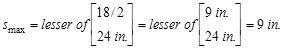
Therefore, maximum stirrup spacing
shall be the smallest of d/2 and 24 in. ACI 318-14 (Table 9.7.6.2.2)
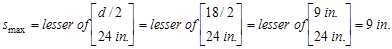
This value
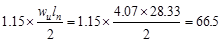
governs over the required stirrup spacing of 19.7 in which was based on the
demand. Note that since the stirrup spacing is governed by smax, the
size of the stirrup can be kept as # 3. Selecting # 4 stirrup size will produce
capacity more than what is required and therefore, be uneconomical.
Check the maximum stirrup spacing
based on minimum shear reinforcement
 in.
(does not govern) ACI 318-14
(10.6.2.2(a))
in.
(does not govern) ACI 318-14
(10.6.2.2(a))
 in.
(does not govern) ACI 318-14 (10.6.2.2(b))
in.
(does not govern) ACI 318-14 (10.6.2.2(b))
Therefore, smax
value is governed by the spacing limit per ACI 318-14 (9.7.6.2.2),
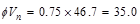
and is equal to 9 in.
Use # 3 @ 8 in.
stirrups
ACI 318-14 (22.5.1.1 and 22.5.10.5.3)
 kips
kips
 kips
>
kips
>  kips
o.k.
kips
o.k.
Compute where is
equal to,
and the stirrups can be stopped
At interior end of the exterior
span, use 16-# 3 @ 8 in o.c., Place 1st stirrup 2 in. from the face
of the column.
Since the preliminary beam depth met minimum depth requirement, the
deflection calculations are not required. A lesser depth maybe possible and
consequently cost savings can be achieved through deflection computations.
Deflection values are calculated and provided for every model created by spBeam
Program and can be used by the engineer to make additional optimization
decisions.
spBeam
Program can be utilized to analyze and design the interior continuous beam
along grid B. The beam is modeled as a three span continuous rectangular beam.
The program
calculates the internal forces (shear force and bending moment), moment and
shear capacities, immediate and long-term deflection results, and required
flexural reinforcement. The graphical and text results are provided here for
both input and output of the spBeam model.
The beam is
modeled as a 36 in. by 21 in. deep rectangular longitudinal beam with column
supports. The supports can be modeled as pinned, fixed, or using actual
geometric properties of the beam-column joint. A value of 100 is used in this
model for column stiffness share, indicating the actual column stiffness. When
the percentage lies between zero and 100%, the joint stiffness contribution by
the column is multiplied by that percentage. The default value is 100%.
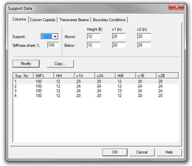
Figure 2.3.6.1 – spBeam Model – Support Data
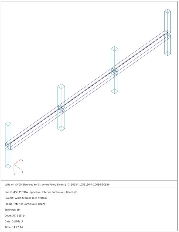
Figure 2.3.6.2 – spBeam Model – Isometric View – Interior
Continuous Beam along Grid B
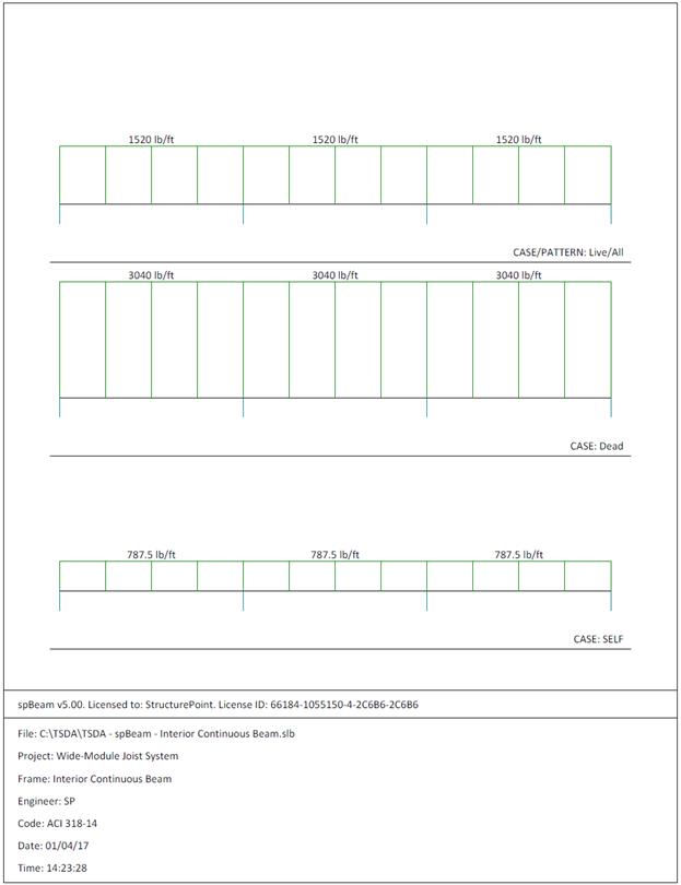
Figure 2.3.6.3 – spBeam Model – Loads (Including Live Load
Patterning)
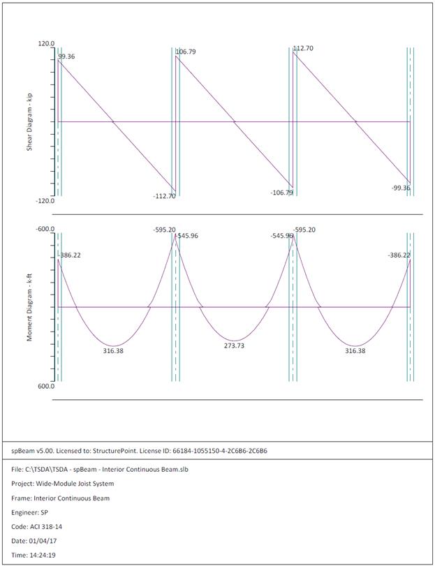
Figure 2.3.6.4 – spBeam Model – Internal Forces (Shear
Force Diagram and Bending Moment Diagram)
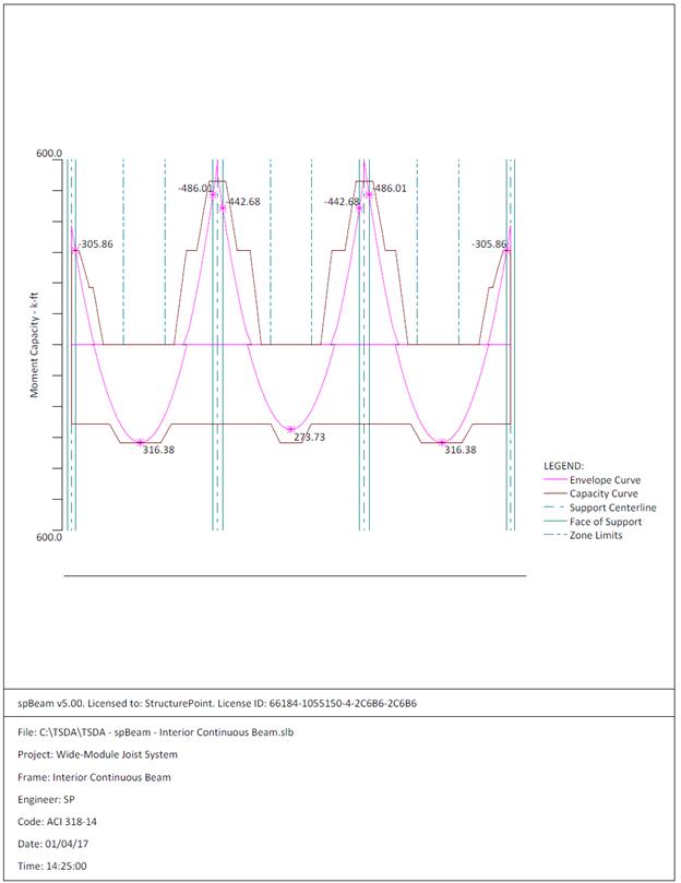
Figure 2.3.6.5 – spBeam Model – Moment Capacity Diagram
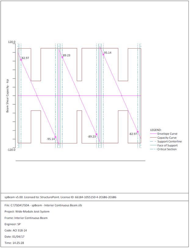
Figure 2.3.6.6 – spBeam Model – Shear Capacity Diagram
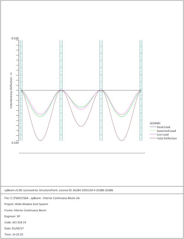
Figure 2.3.6.7 – spBeam Model – Immediate Deflection
Diagram
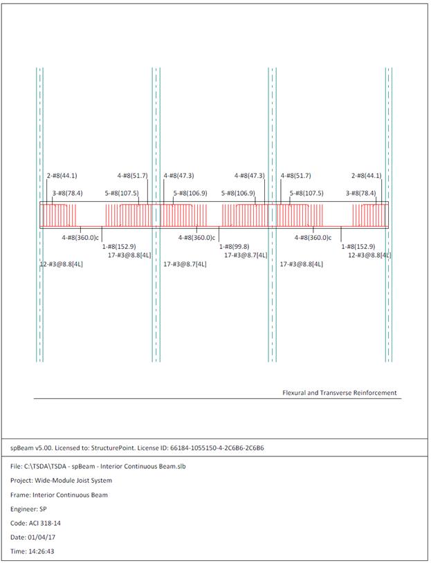
Figure 2.3.6.8 – spBeam Model – Reinforcement Diagram
|
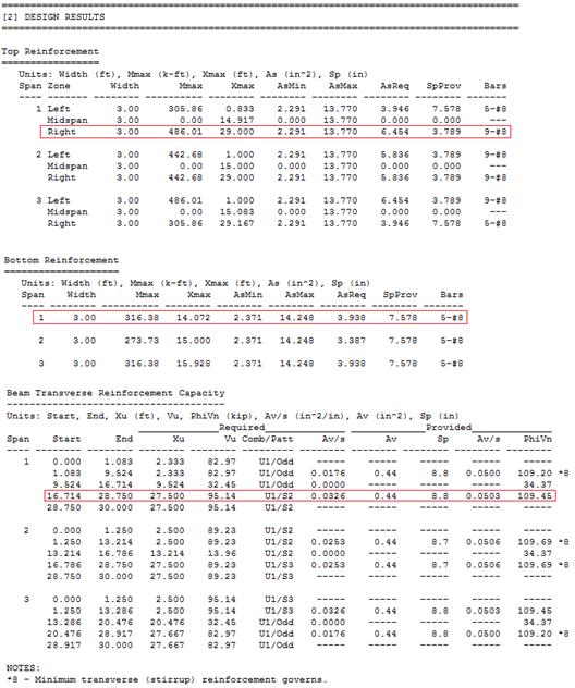
Table 2.3.7.1
– Comparison of Hand Solution with spBeam Solution
|
|
Flexural
Design
|
|
Span
Location
|
Design Moment
(ft-kips)
|
Reinforcement
Required
for Flexure
(in2)
|
Reinforcement
Provided
for Flexure
(in2)
|
|
End Span
|
Hand
Solution
|
spBeam
Solution
|
Hand
Solution
|
spBeam
Solution
|
Hand
Solution
|
spBeam
Solution
|
|
Interior
Negative
|
553.5
|
486.01
|
7.51
|
6.45
|
10-#8
|
9-#8
|
|
Positive
|
344
|
316.4
|
4.22
|
3.94
|
6-#8
|
5-#8
|
|
Shear Design
|
|
|
|
Span
Location
|
Vu
(kips)
|
φVn
(kips)
|
|
|
|
End Span
|
Hand
Solution
|
spBeam
Solution
|
Hand
Solution
|
spBeam
Solution
|
|
|
|
Interior
Negative
|
103.2
|
95.14
|
112.9
|
109.45
|
|
|
In this design example, the interior beam is modeled as a continuous
rectangular longitudinal beam. There is a good agreement between the hand
solution and computer solution. Note that the coefficients traditionally used
to determine moments do not address various types of support and geometry.
The maximum calculated total immediate (instantaneous) deflection (DL +
LL) = 0.529 in., this value can be compared with maximum permissible calculated
deflection limitation per project criteria in accordance to ACI 318-14.
ACI 318-14 (Table 24.2.2)
In addition to
deflection results, parametric studies can be performed in spBeam to optimize design and detailing
results.
The
reinforcement diagram (Figure 2.3.6.8) shows the minimum length required
(including the development length) for flexural design. The bars can be
extended and detailed to provide the required support for shear stirrups.
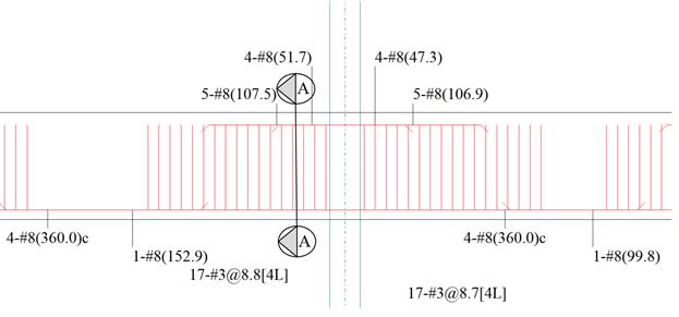
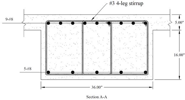
Figure 2.3.8 – Interior Beam Cross-Section (Near the First
Interior Support)
In the wide-module joist construction, the supporting beam depths shall
be same as the overall joist depth. Therefore, the beam depth is set to 21 in.
This beam depth need to satisfy the minimum depth requirement of ACI 318-14 (Table 9.3.1.1) so that the
deflection computations can be waived. The beams of the exterior frame shall be
designed and detailed for the combined effects of flexure, shear, and torsion
according to ACI 318.
Using the minimum depth for
non-prestressed beams in Table 9.3.1.1.
End Span: in
(governs) < 21 in. ACI 318-14 (Table
9.3.1.1)
Interior Span: in
ACI 318-14 (Table 9.3.1.1)
Therefore, the preliminary beam depth satisfies the
minimum depth requirement.

Figure
2.4 – Partial plan view showing interior beam along grid B
Beam (girder)
design involves the following steps:
2.4.1. Determination of span loads
2.4.2. Determination of design moment, shear, and torsion
2.4.3. Flexural and torsion design
2.4.4. Shear and torsion design
2.4.5. Deflections
2.4.6. Computer program solution
2.4.7. Summary and comparison of design results
2.4.8. Conclusions and observations
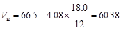
Dead
Load:
Try 24 in width
for the beam (slightly larger than the column width that helps facilitate the
forming, and reduces the beam longitudinal vs. column vertical bar
interference)
Joist & Slab
Weight 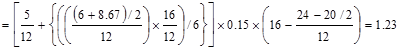 kips/ft
Beam Weight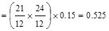 kips/ft
Superimposed
Dead Load, SDL  kips/ft
Live
Load:
Check
for live load reduction per ASCE/SEI
7-10
ASCE/SEI 7-10 (Eq. 4-1)
Where:
reduced
design live load per ft2 of area supported by the member
unreduced
design live load per ft2 of area supported by the member = 80 psf
2
(edge beams without cantilever slabs)
ASCE/SEI 7-10 (Table 4-2)
tributary
area  ft2
ft2
 psf
psf
Which
satisfies requirement for members supporting one floor. ASCE/SEI
7-10 (4.7.2)
 kips/ft
Load
Combination:
The following gravity load combinations are
considered:
ACI 318-14 (Eq. 5.3.1a)
 kips/ft
ACI 318-14 (Eq. 5.3.1b)
 kips/ft
The span loads are governed by the
second load combination.
For factored torsional moment
calculations, the beam self-weight is not included since it is applied along
the beam section centerline. And the moment arm is the distance from the midspan
to the centerline of the exterior beam section = 16/2 – (24/2 - 20/2)/12 = 7.83
ft.
Thus,
the following load combinations are used for the calculation of the factored
torsional moment:
ACI
318-14 (Eq. 5.3.1a)
 kips.ft/ft
ACI 318-14 (Eq. 5.3.1b)
 kips.ft/ft
The span factored torsional moments
are governed by the second load combination.
The factored moment and shear can
be determined using the simplified method if the requirements are
satisfied:
ACI 318-14 (6.5.1)
ü Members are prismatic.
ü Loads are uniformly distributed.
ü L ≤ 3D (0.97 kips/ft ≤
3 x 2.10 kips/ft)
ü There are at least two spans.
ü The longer of two adjacent spans does
not exceed the shorter by more than 20 percent.
Thus, the
approximate coefficients can be used. The factored moments and shears are
determined and summarized in the following
tables. ACI 318-14
(Table 6.5.2 and Table 6.5.3)
|
Table 2.4.2.1
– Exterior Beam Design Flexural Moment Values
|
|
Location
|
Design Flexural
Moment Value
|
|
End Spans
|
Exterior Support Negative
|
 ft-kips ft-kips
|
|
Mid-span
|
 ft-kips ft-kips
|
|
Interior Support Negative
|
 ft-kips ft-kips
|
|
Interior Spans
|
Mid-span Positive
|
 ft-kips ft-kips
|
|
Support Negative
|
 ft-kips ft-kips
|
|
Table 2.4.2.2
– Exterior Design Shear Values
|
|
Location
|
Design Shear
Value
|
|
End Span at Face of First Interior
Support
|
 kips kips
|
|
At Face of all other Supports
|
 kips kips
|
Any structural
analysis method can be used to calculate the torsional. The following table
shows the torsional moment values at the centerline of the supports:
|
Table 2.4.2.3
– Exterior Design Torsional Moment Values
|
|
Location
|
Design Torsional
Moment Value
|
|
At the centerline of all Supports
|
 ft-kips ft-kips
|
For this exterior beam, the end span moment values
govern the design as tabulated in Table 2.4.2.1.
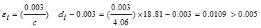
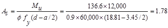
Calculate the required reinforcement to resist the first interior support
negative moment:
 ft-kips
Use #8 bars with 1.5 in. concrete cover per ACI
318-14 (Table 20.6.1.3.1). To avoid interference with joist
negative moment reinforcement, the clear cover to the girder top reinforcement
is required to be increased by lowering the girder top reinforcement. The distance from extreme compression fiber to the
centroid of longitudinal tension reinforcement, d, is calculated below:
To determine the area of steel,
assumptions have to be made whether the section is tension or compression controlled,
and regarding the distance between the resultant compression and tension forces
along the slab section (jd). In this example, tension-controlled section
will be assumed so the reduction factoris
equal to 0.9, and jd will be taken equal to 0.9d since we are
designing for the negative moment in a rectangular beam (narrow compression
zone). The assumptions will be verified once the area of steel is finalized.
Assumein.
Interior
beam width,  in.
in.
The required reinforcement at initial
trial is calculated as follows:
 in.2
in.2
Recalculate
‘a’ for the actual As = 4.49 in.2: 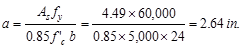
 in.
in.
Therefore,
the assumption that section is tension-controlled is valid.
The
minimum reinforcement shall not be less than
 ACI 318-14
(9.6.1.2(a))
ACI 318-14
(9.6.1.2(a))
And
not less than
 ACI 318-14 (9.6.1.2(b))
All the values on the following
table are calculated based on the procedure outlined above.
|
Table 2.4.3.1
– Reinforcing Design Summary (Flexure only)
|
|
|
End Span
|
Interior Span
|
|
|
Exterior
Negative
|
Positive
|
Interior
Negative
|
Positive
|
Negative
|
|
Design Moment, Mu
(ft-kips)
|
204.7
|
233.9
|
327.5
|
204.7
|
297.7
|
|
Effective depth,
d (in.)
|
18.0*
|
18.625**
|
18.0*
|
18.625**
|
18.0*
|
|
As, req’d
(in.2)
|
2.65
|
2.93
|
4.36
|
2.55
|
3.94
|
|
As, min
(in.2)
|
1.53
|
1.58
|
1.53
|
1.58
|
1.53
|
|
* The beam top bars are to be placed below the joist top
bars.
|
|
** The beam bottom bars are to be placed at the bottom-most
layer. The joist bottom bars, then, shall be spliced at
joist-beam intersection.
|
Torsion requirements for
longitudinal steel have to be determined and combined with reinforcement area
required for flexure.
Calculate the required reinforcement to resist torsion:
Check if
torsional effects can be neglected:
If Tu
< φTth, it shall be permitted to neglect
torsional effects. ACI 318-14
(22.7.1.1)
Where:
 ft-kips
 ft-kips
= Threshold torsion (the calculation of φTth is shown in
the next section)
ft-kips
= Threshold torsion (the calculation of φTth is shown in
the next section)
Since Tu > φTth, the
torsional effects must be considered.
Check if the
factored design torsion can be reduced:
It is permitted
to reduce Tu to φTcr; due to
redistribution of internal forces after torsional cracking; if the exterior
continuous beam meet the following
requirements: ACI 318-14
(22.7.3.2)
1. The beam is statically indeterminate (continuous beam).
2. Tu ≥ φTcr.
To check the
second condition, φTcr need to be calculated as follows:
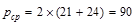
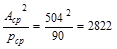
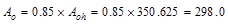
Since the beams are cast monolithically with slab and joists, Acp
(area enclosed by outside perimeter of concrete cross section) and pcp
(outside perimeter of concrete cross section) for the beam can include a
portion of the adjoining slab. The effective width, be, of
the overhanging flange must conform to ACI 318-14 (8.4.1.8):
 in.
(governs)
in.
(governs)
 in.
in.
 in.2
in.2
 in.
in.
 in.3
in.3
The torsional
properties of the beam ignoring the overhanging flange are the following:
 in.2
in.2
 in.
in.
 in.3
> 2796 in.3
in.3
> 2796 in.3
Therefore,
consider the rectangular
section. ACI
318-14 (9.2.4.4(b))
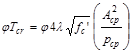 ACI 318-14 (Table 22.7.5.1(a))
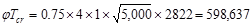 in.-lbs
= 49.9 ft-kips
in.-lbs
= 49.9 ft-kips
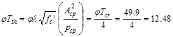 ft-kips
Checking the
second condition of ACI 318-14 (22.7.3.2):
ft-kips
>  ft-kips
Thus, ACI
318-14 permits to reduce Tu to φTcr.
 ft-kips
ACI 318-14 (22.7.3.2)
ft-kips
ACI 318-14 (22.7.3.2)
It is assumed
that the torsional loading on the beam is uniformly distributed along the span.
Determine the adequacy of cross-sectional
dimensions for the torsion:
For solid sections, the limit on
shear and torsion is given by:
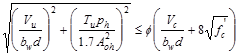 ACI 318-14 (22.7.7.1)
Where:
Aoh = area enclosed by centerline of outermost closed
transverse torsional reinforcement.
ph = perimeter of centerline of outermost closed
transverse torsional reinforcement.
Using d = 18.0 in., the
factored shear force at the critical section located at a distance d
from the face of the support is:
 kips.
kips.
Also, the nominal shear strength
provided by the concrete is:
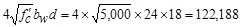
 ACI 318-14 (Eq. 22.5.5.1)
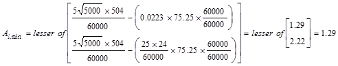
Using a 1.5-in. clear cover to # 3
closed stirrups at bottom and 2.125 in clear cover to # 3 closed stirrups at
top.
 in2
in2
 in
in
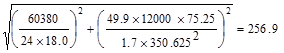 psi
psi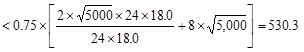 psi
psi
Therefore, the
section is adequate.
Determine the transverse
reinforcement required for torsion:
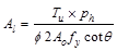
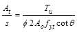 ACI 318-14 (Eq. 22.7.6.1a)
Where
 in2
ACI
318-14 (22.7.6.1.1)
in2
ACI
318-14 (22.7.6.1.1)
 ACI 318-14 (22.7.6.1.2(a))
Therefore,
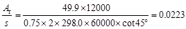 in2
/ in per leg
in2
/ in per leg
Determine the transverse
reinforcement required for shear:
From Table 2.3.2.2 above, the
maximum shear value occurs at the face of the first interior support in the end
span.
kips
The design shear at a distance, d,
away from the face of support,
 kips
kips
Shear strength provided by concrete
ACI 318-14 (Eq. 22.5.5.1)
 lb
lb
 kips
kips
Since ,
shear reinforcement is required.
,
shear reinforcement is required.
The nominal shear strength required
to be provided by shear reinforcement is
 kips
kips
Check whether Vs
is less than
If Vs is greater
than,
then the cross-section has to be revised as ACI 318-14
limits the shear capacity to be provided by stirrups to.
ACI 318-14 (22.5.1.2)
 lb
lb
 kips
kips
Since Vs does not
exceed.
The cross-section is adequate.
Calculate the required transverse
reinforcement for shear as
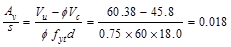 in.2/in.
ACI 318-14
(22.5.10.5.3)
in.2/in.
ACI 318-14
(22.5.10.5.3)
Calculate total required
transverse reinforcement for combined shear and torsion:
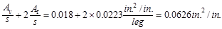
Minimum transverse reinforcement
for shear and torsion is calculated as follows:
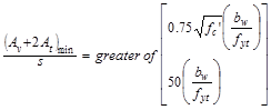 ACI 318-14 (9.6.4.2)
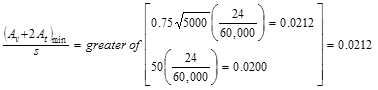 in.2/in.
< 0.0626 in.2/in.
in.2/in.
< 0.0626 in.2/in.
Then, provide 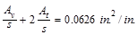
Calculate the required spacing:
Maximum spacing of transverse
torsion reinforcement:
 ACI 318-14 (9.7.6.3.3)
Maximum spacing of transverse shear
reinforcement:
Check whether the
required spacing based on the shear demand meets the spacing limits for shear
reinforcement per ACI 318-14
(9.7.6.2.2).
Check whether Vs
is less than
 lb
lb
 kips
> Vs = 19.43 kips
kips
> Vs = 19.43 kips
Therefore,
maximum stirrup spacing shall be the smallest of d/2 and 24 in.
 ACI 318-14 (Table 9.7.6.2.2)
 (governs)
Using a bundle of 2-#3 closed
stirrups with 2 legs (area per leg  in2),
the required spacing, s, at the critical section is:
in2),
the required spacing, s, at the critical section is:
 in
in
 in
in
Provide a bundle
of 2-#3 closed stirrups with 2 legs spaced at 7 in. on center. #3 bars are
selected for consistency with the transverse reinforcement size used for the
joist and interior beam. The stirrups are bundled at outer legs to maintain A0
value in calculation of At/s for torsion. The bundle of 2-#3 bars
are defined as user-defined reinforcement of size #2 in spBeam Program.
The designer may
choose to utilize #4 closed stirrups with 2 legs at 6 in. on center
alternatively.
In view of the shear and torsion distribution along the span length, this
same reinforcement and spacing can be provided throughout the span length.
Calculate the
additional required longitudinal reinforcement for torsion:
 ACI 318-14 (Eq. 22.7.6.1b)
Where
in.2
ACI 318-14 (22.7.6.1.1)
ACI 318-14 (22.7.6.1.2(a))
Therefore,
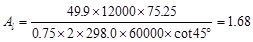 in.2
in.2
The minimum
total area of longitudinal torsional reinforcement:
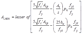 ACI 318-14 (9.6.4.3)
 in.2
in.2
Since Al > Al,min,
use Al = 1.68 in.2
The longitudinal
reinforcement is to be distributed around the perimeter of the stirrups, with a
maximum spacing of 12 in. There shall be at least one longitudinal bar
in each corner of the stirrups.
ACI318-14 (9.7.5.1)
Longitudinal
bars shall have a diameter at least 0.042 times the stirrup spacing, but
not less than 3/8 in.
ACI318-14 (9.7.5.2)
To meet the
maximum spacing requirement, a bar has to be provided between corner bars at
all four sides. This configuration leads to eight-bars; three at top, three at
bottom, and one at each side. Therefore, the reinforcement area per bar is As
= 1.68/8 = 0.21 in.2
Then, use #5 bars for longitudinal bars which also meets minimum
bar diameter requirement of 3/8 in. Al shall be
provided in addition to the required flexural reinforcement at the negative
moment regions (support-top) and positive moment region (mid-span-bottom). At
mid-span-top region where flexural reinforcement is not required for flexure, 3-#5
bars shall be provided. Class B lap splice is to be provided.
|
Table 2.4.3.2 – Reinforcing Design Summary (Flexure + Torsion)
|
|
|
End Span
|
Interior Span
|
|
|
Top
Reinforcing for Exterior Negative Moment
|
Bottom
Reinforcing for Positive Moment
|
Top
Reinforcing for Interior Negative Moment
|
Bottom
Reinforcing for Positive Moment
|
Top
Reinforcing for Interior Negative Moment
|
|
Required
Longitudinal Reinforcement (in.2)
|
2.65
|
2.93
|
4.36
|
2.55
|
3.94
|
|
Required
Torsional Longitudinal Reinforcement (in.2)
|
0.63
|
0.63
|
0.63
|
0.63
|
0.63
|
|
Required
Total Longitudinal Reinforcement (in.2)
|
3.28
|
3.56
|
4.99
|
3.18
|
4.57
|
|
Reinforcement
|
5-#8
|
5-#8
|
7–#8
|
4-#8
|
6-#8
|
Maximum spacing allowed:
Check the requirement for
distribution of flexural reinforcement to control flexural cracking:
ACI 318-14 (Table 24.3.2)
in.
Use ksi
ACI
318-14 (24.3.2.1)
in.
(governs)
in.
Spacing provided for 4-# 8 bars
 in.
in.
o.k.
in.
in.
o.k.
Where ds = 2.625
in. for #3
stirrup.
CRSI 2002 (Figure 12-9)
Check the spacing, s provided, is
greater than the minimum center to center spacing, smin where
CRSI 2002 (Figure 12-9)
Where maximum aggregate size is ¾”
Spacing provided for 7-# 8 bars
 in.
in.
 in.
o.k.
in.
o.k.
Therefore, the reinforcement
selections in the previous table meet the spacing requirements.
Since the preliminary beam depth met minimum depth requirement, the
deflection calculations are not required. A lesser depth maybe possible and
consequently cost savings can be achieved through deflection computations.
Deflection values are calculated and provided for every model created by spBeam
Program and can be used by the engineer to make additional optimization
decisions.
spBeam
Program can be utilized to analyze and design the exterior continuous beam
along grid A. The beam is modeled as a three span continuous rectangular beam.
The program
calculates the internal forces (shear force and bending moment), moment and
shear capacities, immediate and long-term deflection results, and required
flexural reinforcement. The graphical and text results are provided here for
both input and output of the spBeam model.
The beam is
modeled as a 24 in. by 21 in. deep rectangular longitudinal beam with column
supports at 100% stiffness share.


The
reinforcement database is selected as User-defined in order to define a bundle
of 2-#3 bars as #2 with cross-sectional area of 0.22 in2. (Different
than #2 defined earlier for welded wire).
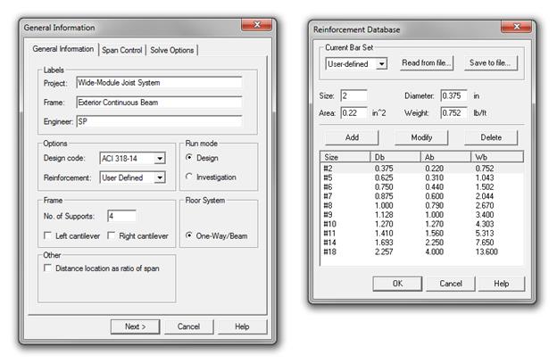
Torsion analysis
was engaged using the torsion analysis and design check box located on the
solve options tab in the input dialog box. The design for torsion is based on a
thin-walled tube, space truss analogy. spBeam allows both equilibrium and
compatibility torsion conditions. In the equilibrium mode, which is assumed by
default, unreduced total value of the torsional design moment is used in the
design. In the compatibility mode, factored torsional moments that exceed
cracking moment Tcr are reduced to the value of Tcr.
However, it is user’s responsibility to determine which mode is appropriate and
the program does not perform any redistribution of internal forces if
compatibility torsion is selected. In this model, the following solve options
were used.
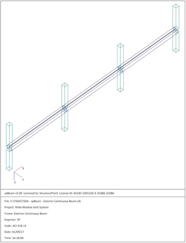
Figure 2.4.6.1 – spBeam Model – Isometric View – Exterior
Continuous Beam along Grid A
Figure 2.4.6.2 – spBeam Model – Loads (Including Live Load
Patterning)
Figure 2.4.6.3 – spBeam Model – Internal Forces (Shear
Force, Torsion, and Bending Moment Diagrams)
Figure 2.4.6.4 – spBeam Model – Moment Capacity Diagram
Figure 2.4.6.5 – spBeam Model – Shear Capacity Diagram
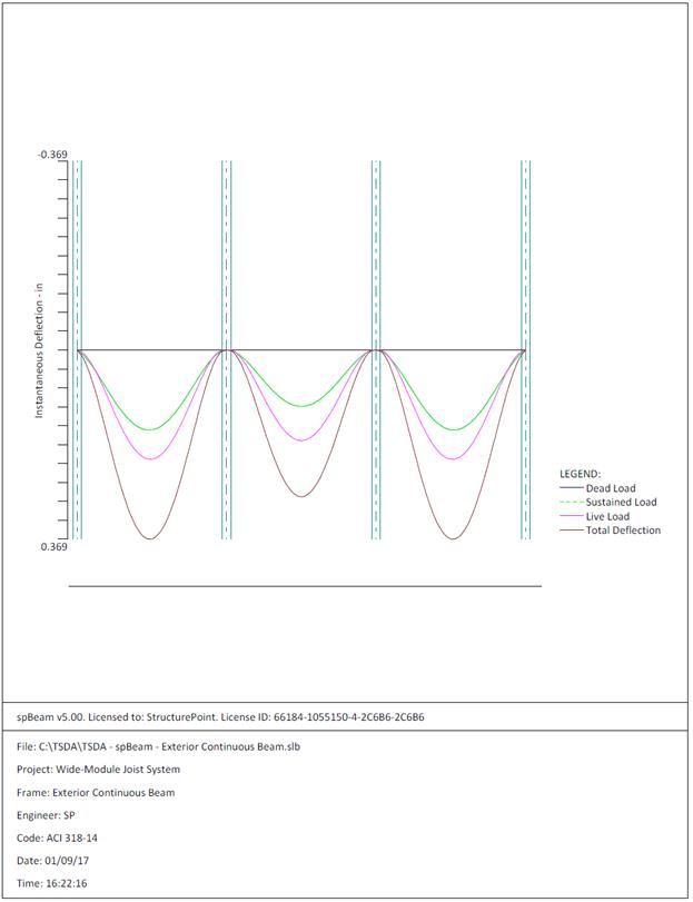
Figure 2.4.6.6 – spBeam Model – Immediate Deflection
Diagram
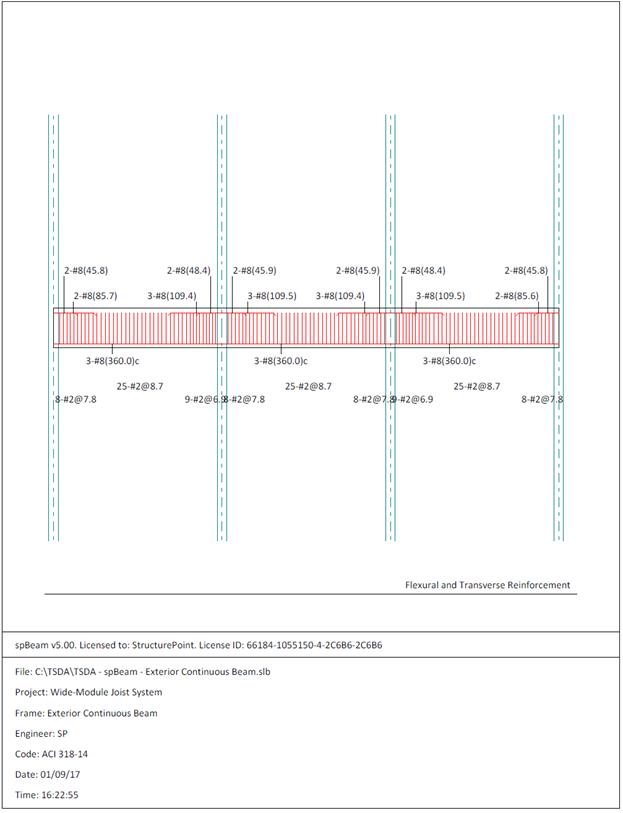
Figure 2.4.6.7 – spBeam Model – Reinforcement Diagram


|
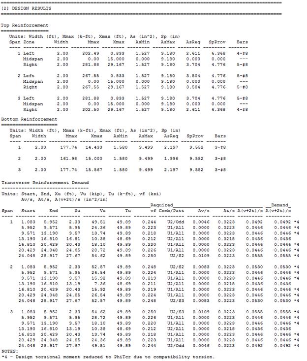
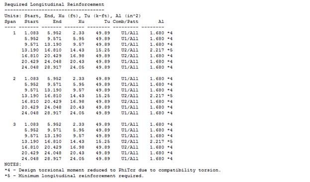
Table 2.4.6.1
– Comparison of Hand Solution with spBeam Solution
|
|
Span
|
Mu (ft-kips)
|
Tu
(ft-kips)
|
At/s
(in2/in per leg)
|
|
End
Span
|
Hand
Solution
|
spBeam
Solution
|
Hand
Solution
|
spBeam
Solution
|
Hand
Solution
|
spBeam
Solution
|
|
Interior
Negative
|
327.5
|
281.9
|
49.9
|
49.9
|
0.0223
|
0.0223
|
|
Span
|
Av/s
(in2/in)
|
(Av+2At)/s
(in2/in)
|
Al (in2)
|
|
End
Span
|
Hand
Solution
|
spBeam
Solution
|
Hand
Solution
|
spBeam
Solution
|
Hand
Solution
|
spBeam
Solution
|
|
Interior
Negative
|
0.018
|
0.011
|
0.0626
|
0.0555
|
1.68
|
1.68
|
|
Table 2.4.6.2
– Comparison of Hand Solution with spBeam Solution (Reinforcement)
|
|
Span Location
|
Required
Reinforcement Area
for Flexure +
Torsion (in2)
|
Reinforcement
Provided
for Flexure +
Torsion
|
|
End
Span
|
Hand
Solution
|
spSlab
Solution
|
Hand
Solution
|
spSlab
Solution
|
|
Interior
Negative
|
4.91
|
3.716+1.680*(3/8)=4.346
|
Top Bar: 7-#8
|
Top Bar: 5-#8 +
3-#8 = 8-#8
|
|
Positive
|
3.53
|
2.203+1.680*(3/8)=2.833
|
Bottom Bar: 5-#8
|
Bottom Bar: 3-#8
+ 3-#8 = 6-#8
|
In this design example, the exterior beam is modeled as a continuous
rectangular longitudinal beam. There is a good agreement between the hand
solution and computer solution. Note that the coefficients traditionally used
to determine moments do not address various types of support and geometry.
The maximum calculated total immediate (instantaneous) deflection (DL +
LL) = 0.369 in., this value can be compared with maximum permissible calculated
deflection limitation per project criteria in accordance to ACI 318-14.
ACI 318-14 (Table 24.2.2)
In addition to
deflection results, parametric studies can be performed in spBeam to optimize design and detailing
results.
The following
observations can be made regarding the reinforcement diagram (Figure 2.4.6.7):
·
The longitudinal reinforcement for the flexural design only and does not
include (Al).
·
Al
is shown in the text output report (Design Results) because it has to be
detailed and distributed to meet the torsional spacing requirements:
o
At least one longitudinal bar must be present at each corner of the
stirrups.
o
And a bar has to
be provided between corner bars at all four sides to meet the maximum spacing
requirement (max 12 in.).
o
This configuration leads to eight-bars in this example: three at top,
three at bottom, and one at each side.
o
Then, for the top bar for the interior negative section for the end span
we need:
1)
The longitudinal reinforcement for the flexural design 5-#8 is required
for flexure.
2)
The longitudinal reinforcement for the torsional design 3-#8 (3 top bars
of the 8 bars distributed around the perimeter of the stirrups). See Table
2.4.6.2.
o
Also, for the bottom bar for the positive section for the end span we
need:
3)
The longitudinal reinforcement for the flexural design 3-#8 is required
for flexure.
4)
The longitudinal reinforcement for the torsional design 3-#8 (3 bottom
bars of the 8 bars distributed around the perimeter of the stirrups). See Table
2.4.6.2.
·
Transverse reinforcement shown reflects the total size and quantity of
stirrups to resist the combined effects of shear and torsion.
·
Top bars minimum length required (including the development length) for
flexural design is shown. The bars can be extended and detailed to provide the
required support for shear stirrups.
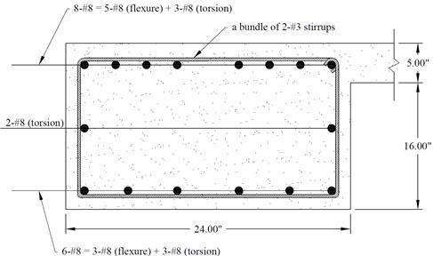
Figure 2.4.7 – Exterior Beam Cross-Section
This section
includes the design of interior, edge, and corner columns using spColumn software.
The preliminary dimensions for these columns were calculated previously in
section 1.2.
Interior Column:
Total Factored Load on 1st
story interior column (@ 1st interior support) are reorganized based
on the calculations on section 1.2 as follows:
PD = Total service dead load  kips
kips
PL = Total service live load kips
kips

Mu,x = unbalance flexural moment at the Interior support
for the interior beam (see Figure 2.3.6.3)
= 595.20 - 545.96 = 49.24 ft-kips
Mu,y = unbalance flexural moment at the interior support for the joist (see
Figure 2.2.6.3)
=154.53 – 141.78 = 12.75 ft-kips
The factored loads are then input into spColumn to construct the axial
load – moment interaction diagram as shown in the sample input below.
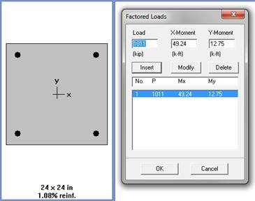
Edge (Exterior) Column:
Total Factored Load on 1st
story edge column (@ 1st interior support) are reorganized based on
the calculations on section 1.2 as follows:
PD = Total service dead load  kips
kips
PL = Total service live load kips
kips
Pu
= 
Mu,x = unbalance flexural moment at the Interior support
(see Figure 2.4.6.3)
= 333.89 – 317.85 = 16.04 ft-kips
Mu,y = torsional moment at the Interior support for the exterior beam (see
Section 2.4.3) + unbalance flexural moment at exterior support for the joist
(see Figure 2.2.6.3)
= 2Tu
+ 73.96 = 2 x 49.9 + 73.96 = 173.76 ft-kips
Corner Column:
Total Factored Load on 1st
story corner column (@ exterior support) are reorganized based on the
calculations on section 1.2 as follows:
PD = Total service dead load  kips
kips
PL = Total service live load kips
kips
Pu
= 
Mu,x = unbalance flexural moment at the Exterior support
(see Figure 2.4.6.3) = 250.25 ft-kips
Mu,y = torsional moment at the Exterior support for the exterior beam (see
Section 2.4.3) + unbalance flexural
moment at exterior support for the joist (see Figure 2.2.6.3)
= Tu
+ 73.96 = 49.9 + 73.96 = 123.86 ft-kips
The axial force and moment
interaction diagram is constructed using spColumn based on geometry and load
input shown below:
Interior Column:
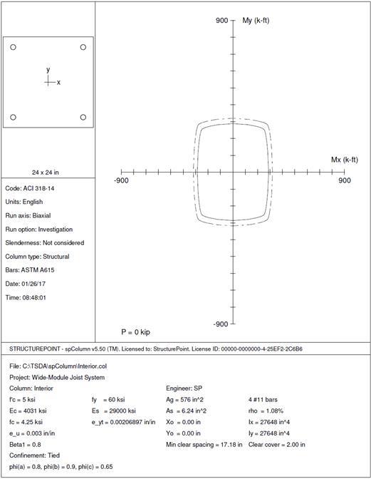
Figure 2.5.2.1 – spColumn Model – Biaxial Moment
Interaction
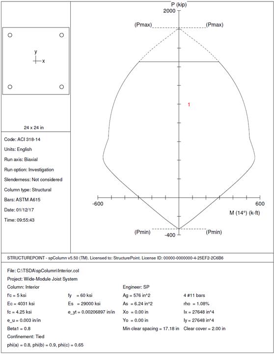
Figure 2.5.2.2 – spColumn Model –Axial Moment Interaction
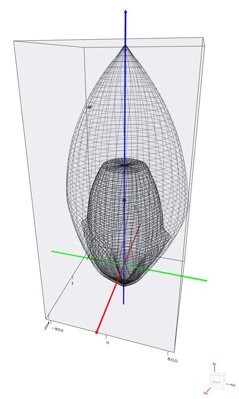
Figure 2.5.2.3 – spColumn Model – Nominal and Factored
Failure Surfaces
Edge (Exterior) Column:
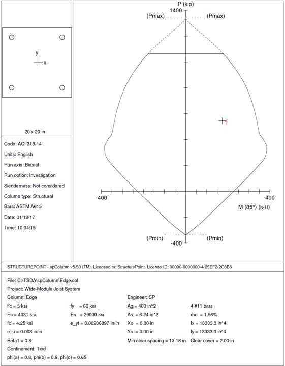
Figure 2.5.2.4 – spColumn Model –Axial Moment Interaction
Corner Column:
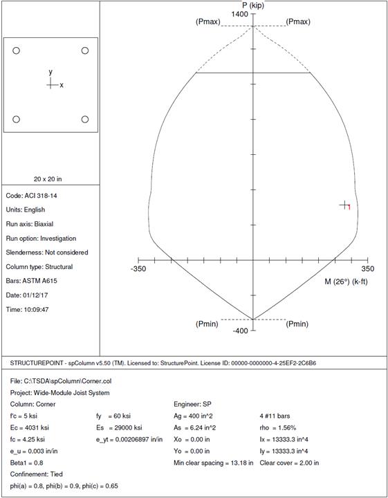
Figure 2.5.2.5 – spColumn Model –Axial Moment Interaction