Reinforced Concrete Shear Wall Foundation (Strip Footing) Analysis and Design
Reinforced Concrete Shear Wall Foundation (Strip Footing) Analysis and Design
Reinforced Concrete Shear Wall Foundation (Strip Footing) Analysis and Design
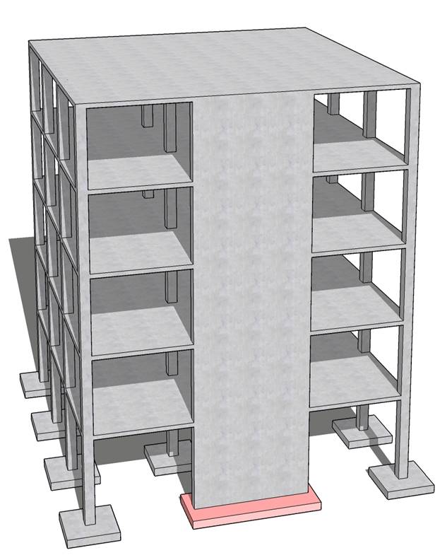
A 12 in. thick structural reinforced concrete shear wall is to be supported by a strip footing. The shear wall carries service dead and live loads of 10 kips/ft and 12.5 kips/ft respectively. The allowable soil pressure is 5000 psf. The wall footing is to be based 5 ft below the final ground surface. Design the footing for flexure, shear and allowable soil pressure.
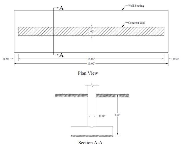
Figure 1 – Reinforced Concrete Wall Footing Geometry
Contents
1.1. Footing Cross Sectional Dimensions
3. Flexural Reinforcement Design
4.2. Shrinkage and Temperature Reinforcement
5. Strip Footing Analysis and Design – spMats Software
6. Design Results Comparison and Conclusions
Code
Building Code Requirements for Structural Concrete (ACI 318-14) and Commentary (ACI 318R-14)
Reference
Reinforced Concrete Mechanics and Design, 7th Edition, 2016, James Wight, Pearson, Example 15-1
spMats Engineering Software Program Manual v8.12, StucturePoint LLC., 2016
Design Data
fc’ = 3,000 psi normal weight concrete
fy = 60,000 psi
Wall thickness = 12 in.
Distance from the ground level to the footing base = 5 ft
Dead load, D = 10 kips/ft
Live load, L = 12.5 kips/ft
Soil density, γs = 120 pcf
Concrete density, γc = 150 pcf for normal weight concrete
Allowable soil pressure, qa = 5000 psf
In order to calculate the allowable net soil pressure, it is necessary to guess the footing thickness for a first trial in order to estimate the footing self-weight. Generally footing thickness of 1 to 1.5 times the wall thickness will be adequate. Assuming the footing thickness is equal to the thickness of the wall (tf = 12 in.).
The allowable net soil pressure is equal to the allowable soil pressure minus the self-weight of the footing and soil weight over the footing:
![]()
This value is the balance of allowable soil pressure available to resist applied loads (dead, live, etc.) from the wall. Estimate the minimum base area of foundation based on unfactored forces and moments transmitted by wall foundation to soil. ACI 318-14 (13.3.1.1)
![]()
Considering a 1 ft strip of wall and footing, the minimum footing width is 5.15 ft. Try 5.17 ft (5 ft 2 in.).
The factored net pressure that will be used in the design of the concrete and reinforcement is equal to:
![]()
For this type of foundation, one-way shear is dominant in comparison with two way shear and is therefore a significant design parameter. The critical section for one-way shear is located at distance d from the face of the wall.
![]()
![]()
![]() ACI 318-14 (22.5.5.1)
ACI 318-14 (22.5.5.1)
![]()
Where ϕ = 0.75 ACI 318-14 (Table 21.2.1)
Vu > ϕVc à Thicker footing is required, try 13 in.
![]()
![]()
![]() ACI 318-14 (22.5.5.1)
ACI 318-14 (22.5.5.1)
![]()
Vu < ϕVc à o.k.
∴ use footing with 13 in. thick and 5 ft 2 in. wide.
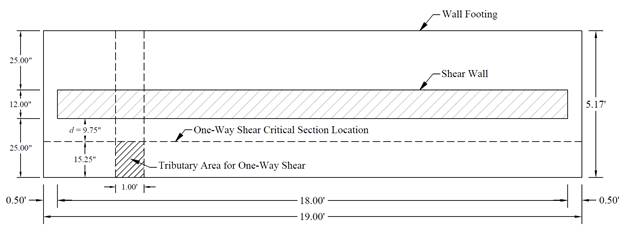
Figure 2 – Strip Footing Plan Showing Tributary Area for One-Way Shear
The critical section for moment is at the face of the wall. The design moment is:
![]()
Use d = 9.75 in.
To determine the area of steel, assumptions have to be made whether the section is tension or compression controlled, and regarding the distance between the resultant compression and tension forces along the footing section (jd). In this example, tension-controlled section will be assumed so the reduction factor ϕ is equal to 0.9, and jd will be taken equal to 0.95d. The assumptions will be verified once the area of steel in finalized.
![]()
![]()
![]()
![]()
![]()
Therefore, the assumption that section is tension-controlled is valid.
![]()
 ACI 318-14 (7.6.1.1)
![]()
![]() ACI 318-14 (7.7.2.3)
ACI 318-14 (7.7.2.3)
Provide #4 bars at 7 in. on centers (≤ smax) with As = 0.34 in.2/ft. Note that #5 bars at 11 in. on centers with As = 0.34 in.2/ft can be also used. Reinforcement along the wall length is governed by shrinkage and temperature requirements and is detailed below.
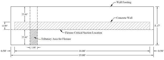
Figure 3 – Strip Footing Plan Showing Tributary Area for Flexure
Check if the simplified development length equation can be used:
Bars used are #4 (< #6)
Clear spacing of the bars being developed exceeds 2db (7 – 0.5 = 6.5 in. > 2 x 0.5 = 1.0 in.)
Clear cover exceeds db (3 – 0.5 = 2.5 in. > 0.5 in.)
Use the simplified equation:
 ACI 318-14 (Table 25.4.2.2)
Where:
![]() (Light
weight modification factor: normal weight concrete) ACI 318-14 (Table 25.4.2.4)
(Light
weight modification factor: normal weight concrete) ACI 318-14 (Table 25.4.2.4)
![]() (Casting
position modification factor: less than 12 in. of fresh concrete placed below
horizontal reinforcement) ACI 318-14 (Table 25.4.2.4)
(Casting
position modification factor: less than 12 in. of fresh concrete placed below
horizontal reinforcement) ACI 318-14 (Table 25.4.2.4)
![]() (Epoxy
modification factor: uncoated or zinc-coated reinforcement) ACI 318-14 (Table 25.4.2.4)
(Epoxy
modification factor: uncoated or zinc-coated reinforcement) ACI 318-14 (Table 25.4.2.4)
The provided bar length is equal to:
![]() à o.k.
à o.k.
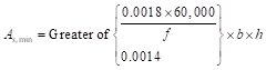
Shrinkage and temperature reinforcement is checked along the length of the footing and is calculated as follows:
 ACI 318-14 (24.4.3.2)
![]()
![]() ACI 318-14 (24.4.3.3)
ACI 318-14 (24.4.3.3)
Provide 5-#5 bars at 13.84 in. on centers (≤ smax) with As = 1.55 in.2 (Note that 3-#7 bars at 18 in. on centers with As = 1.80 in.2 can be also used).
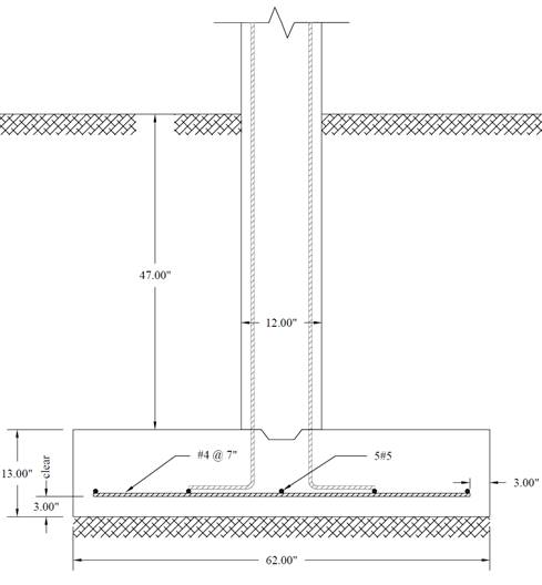
Figure 4 – Wall Footing Reinforcement Details
spMats uses the Finite Element Method for the structural modeling and analysis of reinforced concrete slab systems or mat foundations subject to static loading conditions.
The slab, mat, or footing is idealized as a mesh of rectangular elements interconnected at the corner nodes. The same mesh applies to the underlying soil with the soil stiffness concentrated at the nodes. Slabs of irregular geometry can be idealized to conform to geometry with rectangular boundaries. Even though slab and soil properties can vary between elements, they are assumed uniform within each element.
For illustration and comparison purposes, the following figures provide a sample of the input modules and results obtained from an spMats model created for the reinforced concrete strip footing (shear wall foundation) in this example.
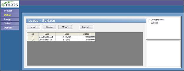
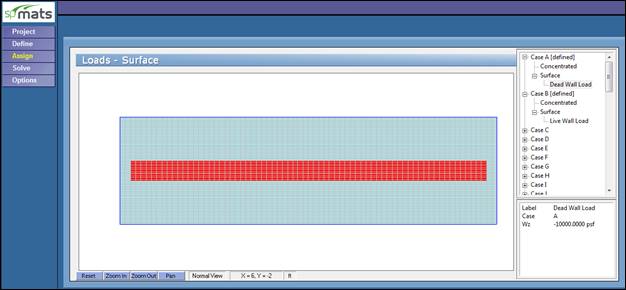
Figure 5 –Defining and Assigning Loads (spMats)
The following 3 figures provide relevant segments of spMats model results output:
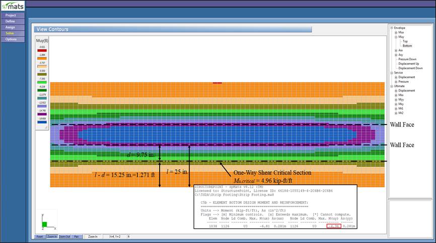
Figure 6 –Ultimate Moment Contour (spMats)
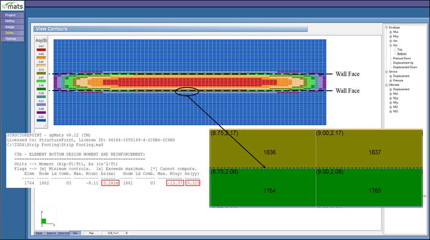
Figure 7 –Required Reinforcement Contour (spMats)
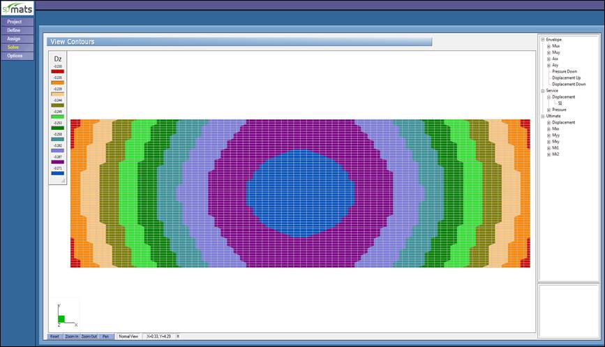
Figure 8 –Vertical Displacement Contour (spMats)
|
Table 1 – Comparison of Strip Footing Analysis and Design Results |
||||
|
|
Mu (kip-ft/ft) |
Vu (kips/ft) |
As,min (in.2/ft) |
As,required (in.2/ft) |
|
Hand |
13.40 |
7.87 |
0.28 |
0.316 |
|
Reference |
13.40 |
8.51 |
0.28 |
0.330 |
|
13.37 |
7.81 |
0.28 |
0.315 |
|
Where Vu is obtained from spMats using the value of Mu at the one-way shear critical section (at distance d from the face of the wall) as follows (see Figure 6):
![]()
The results of all the hand calculations and the reference used illustrated above are in precise agreement with the automated exact results obtained from the spMats program except where the author made simplifying assumptions.
For example, the reference calculated required reinforcement area and one-way shear at the critical section based on three simplification assumptions:
![]()
![]()
![]()
spMats results show exact values for jd and d, resulting in lower required area of steel. Similar differences in one-way shear values as the reference uses the initial assumption of the footing thickness to calculate the applied factored shear instead of the final selected footing thickness (13 in.) used in spMats and hand solution.
The required reinforcement is calculated in spMats by default based on maximum moment within an element (the upper left or right nodes from element 1764 as shown in Figure 7). If the “average moment within an element” option is selected by the user to compute the required reinforcement, then the averaged required reinforcement for the two adjacent elements 1764 and 1836 should be used for comparison.
When defining the design parameters in spMats, close attention should be paid to locating the top and bottom layers of reinforcement in both the x- and y-directions. In this example, the main reinforcement is located along the y-axis, then locating the reinforcement layer along the y-axis at the bottom of the reinforcement layer along the x-axis will lead to a more economical design. The following Figure shows the Design Parameters module in spMats with values used in this example where 3 in. clear cover and #4 bars are used.
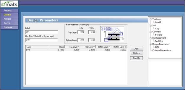
Figure 9 –Defining Design Parameters (spMats)