Reinforced Concrete Column Combined Footing Analysis and Design
Reinforced Concrete Column Combined Footing Analysis and Design
Reinforced Concrete Column Combined Footing Analysis and Design
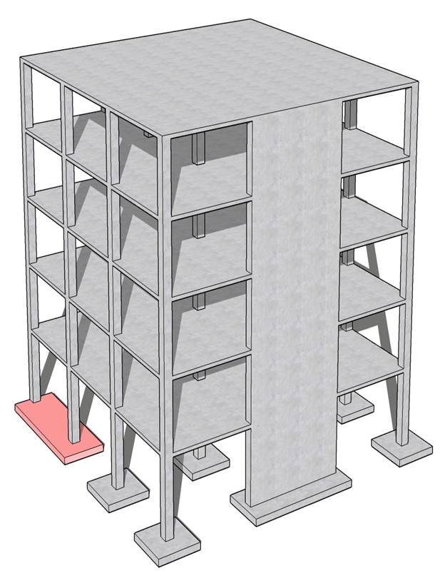
A combined footing was selected to support a 24 in. x 16 in. exterior column near a property line and a 24 in. x 24 in. Interior column. Each column carries the service dead and live loads shown in the following figure. The footing dimensions (25 ft 4 in. x 8 ft) were selected such that the centroid of the area in contact with soil coincides with the resultant of the column loads supported by the footing.
Check if the selected combined footing preliminary thickness of 36 in. is sufficient to resist two-way punching shear around the interior and exterior columns supported by the footing. Compare the calculated results with the values presented in the Reference and model results from spMats engineering software program from StructurePoint.
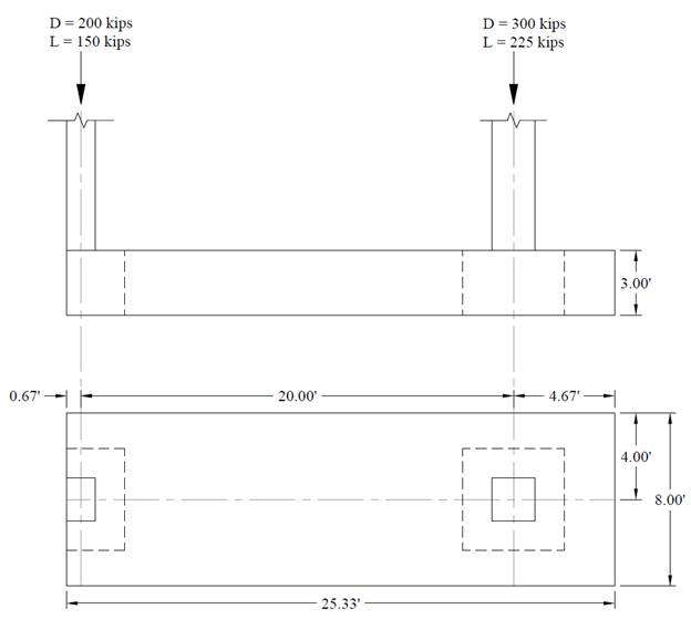
Figure 1 – Reinforced Concrete Combined Footing Geometry
Contents
1.1. Footing Cross Sectional Dimensions
2. Two-Way (Punching) Shear Capacity Check
3. One-Way Shear Capacity Check
4. Flexural Reinforcement Design
4.1. Negative Moment (Midspan)
4.2. Positive Moment (At Interior Column)
5. Combined Footing Analysis and Design – spMats Software
6. Design Results Comparison and Conclusions
Code
Building Code Requirements for Structural Concrete (ACI 318-14) and Commentary (ACI 318R-14)
Reference
Reinforced Concrete Mechanics and Design, 7th Edition, 2016, James Wight, Pearson, Example 15-5
spMats Engineering Software Program Manual v8.12, StucturePoint LLC., 2016
Design Data
fc’ = 3,000 psi normal weight concrete
fy = 60,000 psi
Preliminary footing thickness = 36 in.
Dead load, D = 200 kips for exterior column and 300 kips for interior column
Live load, L = 150 kips for exterior column and 225 kips for interior column
Soil density, γs = 120 pcf
Concrete density, γc = 150 pcf for normal weight concrete
Allowable soil pressure, qa = 5000 psf
Footing length = 25 ft 4 in.
Footing width = 8 ft
Preliminary footing depth = 36 in. with effective depth, d = 32.5 in.
The footing dimensions (25 ft 4 in. x 8 ft) were selected by the reference such that the centroid of the area in contact with soil coincides with the resultant of the column loads supported by the footing to achieve uniform soil pressures.
The factored net pressure that will be used in the design of the concrete and reinforcement is equal to:
![]()
The following Figure shows the shear and moment diagrams for the combined footing based on the factored columns loads and the factored net pressure.
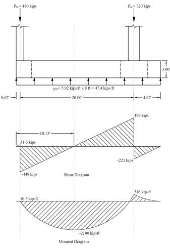
Figure 2 – Shear Force and Bending Moment Diagrams
Two-way shear is critical on a rectangular section located at d/2 away from the face of the column as shown in the following Figures, Where:
b1 = Dimension of the critical section ![]() measured in the direction of the span for which
moments are determined in ACI 318, Chapter 8.
measured in the direction of the span for which
moments are determined in ACI 318, Chapter 8.
b2 = Dimension of the critical section ![]() measured in the direction perpendicular to b1
in ACI 318, Chapter 8 (see Figure 5).
measured in the direction perpendicular to b1
in ACI 318, Chapter 8 (see Figure 5).
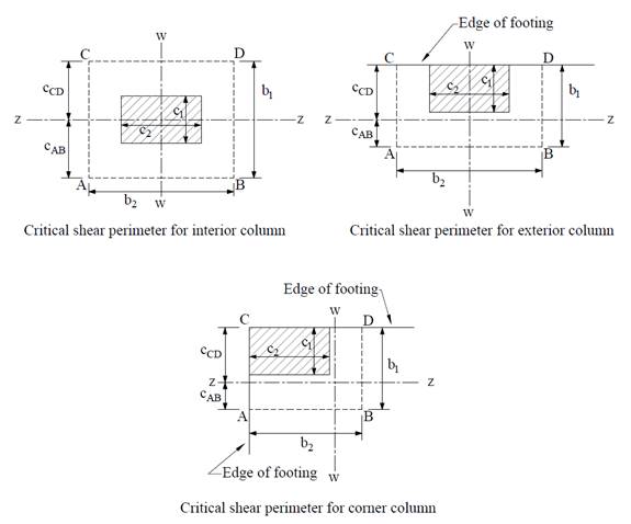
Figure 3 – Critical Shear Perimeters around Columns
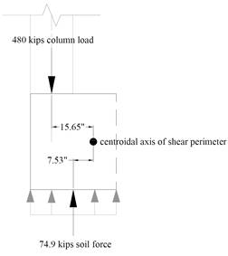
The factored shear force (Vu) at the critical section is computed as the reaction at the centroid of the critical section minus the force due to soil pressure acting within the critical section (d/2 away from column face).
![]()
The factored unbalanced moment used for shear transfer, Munb, is computed as the sum of the joint moments to the left and right. Moment of the vertical reaction with respect to the centroid of the critical section is also taken into account.
![]()
![]()
![]()
For the interior column, the location of the centroidal axis z-z is:
![]()
The polar moment Jc of the shear perimeter is:
![]()
![]()
![]() ACI 318-14 (8.4.2.3.2)
ACI 318-14 (8.4.2.3.2)
![]()
![]() ACI 318-14 (Eq. 8.4.4.2.2)
ACI 318-14 (Eq. 8.4.4.2.2)
The length of the critical perimeter for the exterior column:
![]()
The two-way shear stress (vu) can then be calculated as:
![]() ACI 318-14 (R.8.4.4.2.3)
ACI 318-14 (R.8.4.4.2.3)
![]()
![]() ACI 318-14 (Table 22.6.5.2)
ACI 318-14 (Table 22.6.5.2)
![]()
![]()
![]()
Since ϕvc > vu at the critical section, the slab has adequate two-way shear strength at this joint.
![]()
![]()
![]()
![]()
For the exterior column, the location of the centroidal axis z-z is:
![]()
The polar moment Jc of the shear perimeter is:
![]()
![]()
![]() ACI 318-14 (8.4.2.3.2)
ACI 318-14 (8.4.2.3.2)
![]()
![]() ACI 318-14 (Eq. 8.4.4.2.2)
ACI 318-14 (Eq. 8.4.4.2.2)
The length of the critical perimeter for the exterior column:
![]()
The two-way shear stress (vu) can then be calculated as:
![]() ACI 318-14 (R.8.4.4.2.3)
ACI 318-14 (R.8.4.4.2.3)
![]()
![]() ACI 318-14 (Table 22.6.5.2)
ACI 318-14 (Table 22.6.5.2)
![]()
![]()
![]()
Since ϕvc < vu at the critical section, the slab does not have adequate two-way shear strength at this joint.
Increase the footing thickness to 40 in. with effective depth, d = 36.5 in.
![]()
![]()
![]()
![]()
For the exterior column, the location of the centroidal axis z-z is:
![]()
The polar moment Jc of the shear perimeter is:
![]()
![]()
![]() ACI 318-14 (8.4.2.3.2)
ACI 318-14 (8.4.2.3.2)
![]()
![]() ACI 318-14 (Eq. 8.4.4.2.2)
ACI 318-14 (Eq. 8.4.4.2.2)
The length of the critical perimeter for the exterior column:
![]()
The two-way shear stress (vu) can then be calculated as:
![]() ACI 318-14 (R.8.4.4.2.3)
ACI 318-14 (R.8.4.4.2.3)
![]()
![]() ACI 318-14 (Table 22.6.5.2)
ACI 318-14 (Table 22.6.5.2)
![]()
![]()
![]()
Since ϕvc > vu at the critical section, the slab has adequate two-way shear strength at this joint.
Use a combined footing 25 ft 4 in. by 8 ft in plan, 3 ft 4 in. thick, with effective depth 36.5 in.
The critical section for one-way shear is located at distance d from the face of the column. The one-way shear capacity of the foundation can be calculated using the following equation:
![]() ACI 318-14 (22.5.5.1)
ACI 318-14 (22.5.5.1)
Where ϕ = 0.75 ACI 318-14 (Table 21.2.1)
This example focus on the calculation of two-way shear capacity for combined foundation. For more details on the one-way shear check for foundation check “Reinforced Concrete Shear Wall Foundation (Strip Footing) Analysis and Design” example.
The critical section for moment is shown in the moment diagram in Figure 2. The design moment is:
![]()
Use d = 36.5 in.
To determine the area of steel, assumptions have to be made whether the section is tension or compression controlled, and regarding the distance between the resultant compression and tension forces along the footing section (jd). In this example, tension-controlled section will be assumed so the reduction factor ϕ is equal to 0.9, and jd will be taken equal to 0.95d. The assumptions will be verified once the area of steel in finalized.
![]()
![]()
![]()
![]()
![]()
Therefore, the assumption that section is tension-controlled is valid.
![]()
Depending of the method of analysis the minimum area of reinforcement shall be calculated using beam provisions or one-way slab provisions. In this case both beam and slab provisions will be illustrated.
For beam provisions:
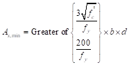 ACI 318-14 (9.6.1.2)
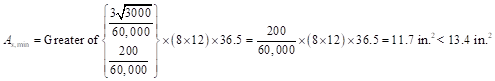
Use 17-#8 top bars with As = 13.43 in.2 at midspan.
For slab provisions:
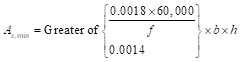 ACI 318-14 (7.6.1.1)
![]()
Use 17-#8 top bars with As = 13.43 in.2 at midspan.
In spMats, the slab provisions for minimum reinforcement can be used since the finite element analysis calculates the required area of steel in both the x (longitudinal) and y (transverse) direction independently.
For beam provisions:
Repeating the same process at Section 4.1, As = 3.3 in.2 << As,min = 11.7 in.2. Thus, use 15-#8 bottom bars with As = 11.9 in.2 at the interior column.
For slab provisions:
Repeating the same process at Section 4.1, As = 3.3 in.2 << As,min = 6.91 in.2. Thus, use 9-#8 bottom bars with As = 7.11 in.2 at the interior column.
Note code provisions permit the use of reinforcement of one third more than is required by analysis in some cases.
spMats uses the Finite Element Method for the structural modeling and analysis of reinforced concrete slab systems or mat foundations subject to static loading conditions.
The slab, mat, or footing is idealized as a mesh of rectangular elements interconnected at the corner nodes. The same mesh applies to the underlying soil with the soil stiffness concentrated at the nodes. Slabs of irregular geometry can be idealized to conform to geometry with rectangular boundaries. Even though slab and soil properties can vary between elements, they are assumed uniform within each element.
For illustration and comparison purposes, the following figures provide a sample of the input modules and results obtained from spMats models created for the reinforced concrete combined footing at a property line in this example. Two models were created for this example (the first model for the footing with 36 in. thickness that failed in punching shear check around the exterior column, and the second model for the same footing with a revised thickness of 40 in.).
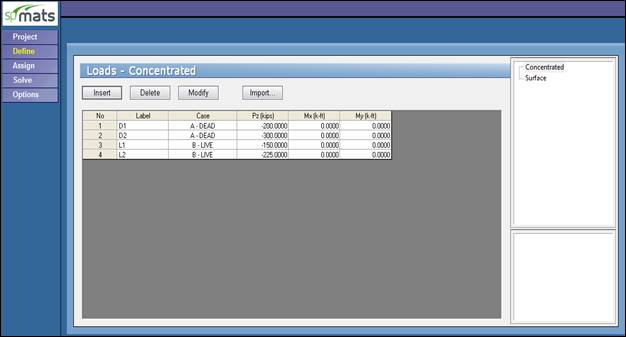
Figure 4 –Defining Service Loads (spMats)
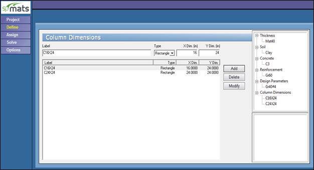
Figure 5 –Defining Columns Dimensions (spMats)
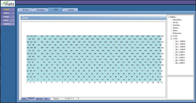
Figure 6 –Mesh Generation (spMats) Showing Node & Element Numbering
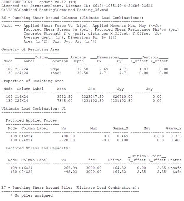
Figure 7 – Punching Shear Output 36 in. Strip Footing (spMats)
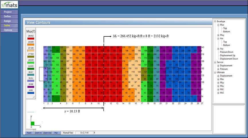
Figure 8 – Ultimate Moment Contour 40 in. Footing (spMats)
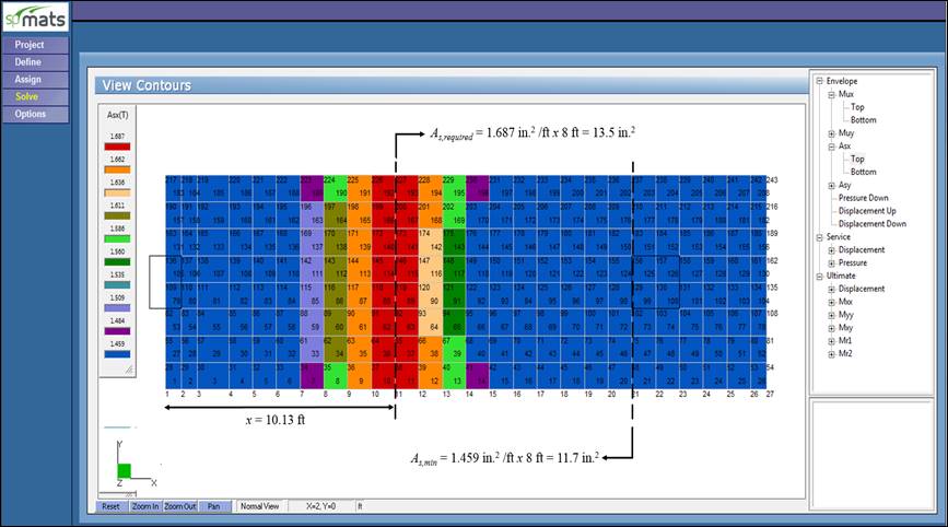
Figure 9 – Required Reinforcement Contour 40 in. Footing (spMats)
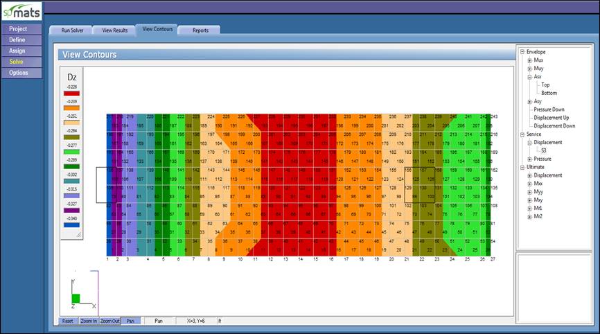
Figure 10 –Vertical Displacement Contour 40 in. Footing (spMats)
|
Table 1 - Comparison of Two-Way (Punching) Shear Check Results for Footing with 36 in. Thickness |
|||||||||
|
Support |
b1, in. |
b2, in. |
cAB, in. |
||||||
|
Reference |
Hand |
Reference |
Hand |
Reference |
Hand |
||||
|
Exterior |
32.25 |
32.25 |
32.25 |
56.5 |
56.5 |
56.5 |
8.6 |
8.6 |
8.6 |
|
Interior |
56.5 |
56.5 |
56.5 |
56.5 |
56.5 |
56.5 |
28.25 |
28.25 |
28.25 |
|
|
|||||||||
|
Support |
Jc, in.4 |
γv |
Vu, kips |
||||||
|
Reference |
Hand |
Reference |
Hand |
Reference |
Hand |
||||
|
Exterior |
621,000 |
620,710 |
620,710 |
0.335 |
0.335 |
0.335 |
480 |
480 |
480 |
|
Interior |
--- |
4,231,103 |
4,231,103 |
--- |
0.4 |
0.4 |
720 |
720 |
720 |
|
|
|||||||||
|
Support |
Mu,punching, kips-ft |
vu, psi |
ϕvc, psi |
||||||
|
Reference |
Hand |
Reference |
Hand |
Reference |
Hand |
||||
|
Exterior |
579 |
579 |
943 |
192 |
192 |
267 |
164 |
164.3 |
164.3 |
|
Interior |
0 |
0 |
0 |
80.2 |
80.2 |
98 |
164 |
164.3 |
164.3 |
|
Table 2 - Flexural Reinforcement Comparison - Longitudinal Direction |
||||||||
|
Mu, kips-ft |
As,required, in.2 |
As,min, in.2 |
||||||
|
Reference |
Hand |
Reference |
Hand |
Reference |
Hand* |
|||
|
2100 |
2100 |
2132 |
13.5 |
13.4 |
13.5 |
11.7 |
11.7 |
11.7 |
|
* Using beam provisions to find As,min to be consistent with Reference approach. However, engineering judgment need to be taken to decide if the combined footing need to be treated as a one-way slab or beam. |
||||||||
The results of all the hand calculations and the reference used illustrated above are in agreement with the automated exact results obtained from the spMats program except for vu values.
In spMats, the factored unbalanced moment used for shear transfer, Munb, is calculated as the sum of the moments at finite element nodes within the critical section (resisting zone). Moment of the vertical reaction with respect to the centroid of the critical section is also taken into account. The reference take into account only the moments of the vertical reaction and soil pressure with respect to the centroid of the critical section.