Precast Concrete Bearing Wall Panel Design (Alternative Analysis Method) (Using ACI 318-14)
Precast Concrete Bearing Wall Panel Design (Alternative Analysis Method) (Using ACI 318-14)
Precast Concrete Bearing Wall Panel Design (Alternative Analysis Method) (Using ACI 318-14)
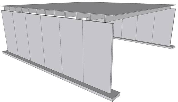
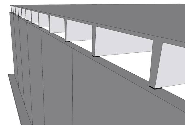
A structural precast reinforced concrete wall panel in a single-story building provides gravity and lateral load resistance for the following applied loads:
Weight of 10DT24 = 468 plf
Roof dead load = 20 psf
Roof live load = 30 psf
Wind load = 30 psf
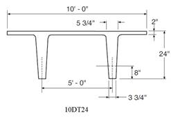
The 10DT24 are spaced 5 ft on center. The assumed precast wall panel section and reinforcement are investigated after analysis to verify suitability for the applied loads then compared with numerical analysis results obtained from spWall engineering software program from StructurePoint.
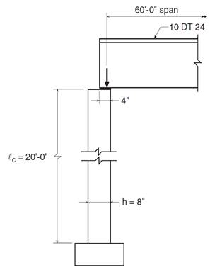
Figure 1 – Reinforced Concrete Precast Wall Panel Geometry
Contents
1. Minimum Vertical Reinforcement
2. Alternative Method for Out-of-Plane Slender Wall Analysis Applicability
3.1. Roof load per foot width of wall
3.2. Calculation of maximum wall forces
3.3. Tension-controlled verification
4. Wall Cracking Moment Capacity (Mcr)
5. Wall Flexural Moment Capacity (ϕMn)
8. Wall Mid-Height Deflection (Δs)
9. Precast Concrete Bearing Wall Panel Analysis and Design – spWall Software
10. Design Results Comparison and Conclusions
Code
Building Code Requirements for Structural Concrete (ACI 318-14) and Commentary (ACI 318R-14)
Reference
Notes on ACI 318-11 Building Code Requirements for Structural Concrete, Twelfth Edition, 2013 Portland Cement Association, Example 21.3
spWall Engineering Software Program Manual v5.01, STRUCTUREPOINT, 2016
Design Data
fc’ = 4,000 psi normal weight concrete (wc = 150 pcf)
fy = 60,000 psi
Wall length = 20 ft
Assumed wall thickness = 8 in.
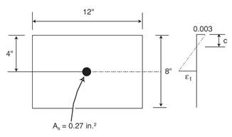
Assumed vertical reinforcement: single layer of #4 bars at 9 in. (As, vertical = 0.20 / 9 in. x 12 in. = 0.27 in.2/ft)
![]() ACI 318-14 (2.2)
ACI 318-14 (2.2)
![]() ACI 318-14 (Table 11.6.1)
ACI 318-14 (Table 11.6.1)
![]()
![]() ACI 318-14 (11.7.2.1)
ACI 318-14 (11.7.2.1)
![]()
Precast concrete walls can be analyzed using the provisions of Chapter 11 of the ACI 318. Most walls, and especially slender walls, are widely evaluated using the “Alternative Method for Out-of-Plane Slender Wall Analysis” in Section 11.8. The requirements of this procedure are summarized below:
· The cross section shall be constant over the height of the wall ACI 318-14 (11.8.1.1(a))
· The wall can be designed as simply supported ACI 318-14 (11.8.2.1)
· Maximum moments and deflections occurring at midspan ACI 318-14 (11.8.2.1)
· The wall must be axially loaded ACI 318-14 (11.8.2.1)
· The wall must be subjected to an out-of-plane uniform lateral load ACI 318-14 (11.8.2.1)
· The wall shall be tension-controlled ACI 318-14 (11.8.1.1(b))
· The reinforcement shall provide design strength greater than cracking strength ACI 318-14 (11.8.1.1(c))
· Pu at the midheight section does not exceed 0.06 fc’Ag ACI 318-14 (11.8.1.1(d))
· Out-of-plane deflection due to service loads including PΔ effects does not exceed lc/150
ACI 318-14 (11.8.1.1(c))
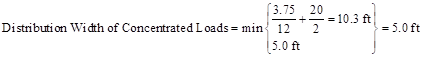
ACI 318 requires that concentrated gravity loads applied to the wall above the design flexural section shall be assumed to be distributed over a width: ACI 318-14 (11.8.2.2)
a) Equal to the bearing width, plus a width on each side that increases at a slope of 2 vertical to 1 horizontal down to the design section
b) Not greater than the spacing of the concentrated loads
c) Not extending beyond the edges of the wall panel.
 ACI 318-14 (11.8.2.2)
 Wall Structural Analysis
Using 14.8 provisions, calculate factored loads as follows for each of the considered load combinations:
![]()
![]()
![]()
![]()
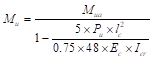
The calculation of maximum factored wall forces in accordance with 11.8 is summarized in Figure 2 including moment magnification due to second order (P-Δ) effects.
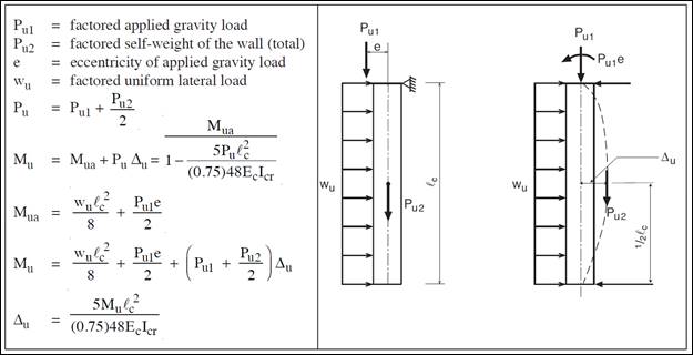
Figure 2 – Wall Structural Analysis According to the Alternative Design of Slender Walls Method (PCA Notes)
For load combination #1 (U = 1.4 D):
![]()
 ACI 318-14 (11.8.3.1d)
![]()
Where Mua is the maximum factored moment at midheight of wall due to lateral and eccentric vertical loads, not including PΔ effects. ACI 318-14 (11.8.3.1)
![]() ACI 318-14 (19.2.2.1.b)
ACI 318-14 (19.2.2.1.b)
![]() ACI 318-14 (11.8.3.1c)
ACI 318-14 (11.8.3.1c)
![]() ACI 318-14 (11.8.3.1)
ACI 318-14 (11.8.3.1)
Calculate the effective area of longitudinal reinforcement in a slender wall for obtaining an approximate cracked moment of inertia.
![]() ACI 318-14 (R11.8.3.1)
ACI 318-14 (R11.8.3.1)
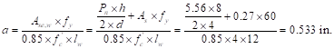
The following calculation are performed with the effective area of steel in lieu of the actual area of steel.
![]()
![]()
![]() ACI 318-14 (11.8.3.1c)
ACI 318-14 (11.8.3.1c)
![]()
Therefore, section is tension controlled ACI 318-14 (Table 21.2.2)
![]() ACI 318-14 (Table 21.2.2)
ACI 318-14 (Table 21.2.2)
ACI 318-14 (11.8.3.1d)
The steps above are repeated for all the considered load combinations, Table 1 shows the factored loads at mid-height of wall for all of these load combinations.
|
Table 1 - Factored load combinations at mid-height of wall |
|||||||||||
|
Load Combination |
Pu, kips |
Mua, in.-kips |
Ec, ksi |
n |
Ase,w, in.2/ft |
a, in. |
c, in. |
Icr, in.4 |
εt, in./in. |
φ |
Mu, in.-kips |
|
1.4 D |
4.2 |
3.8 |
3,605 |
8 |
0.34 |
0.50 |
0.59 |
32.5 |
0.0173 |
0.9 |
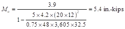
5.4 |
|
1.2 D + 1.6 Lr + 0.8 W |
5.0 |
19.2 |
3,605 |
8 |
0.35 |
0.51 |
0.60 |
33.2 |
0.0170 |
0.9 |
28.8 |
|
1.2 D + 0.5 Lr +1.6 W |
4.1 |
32.4 |
3,605 |
8 |
0.34 |
0.50 |
0.59 |
32.5 |
0.0173 |
0.9 |
45.0 |
|
0.9 D + 1.6 W |
2.7 |
31.2 |
3,605 |
8 |
0.32 |
0.47 |
0.55 |
31.1 |
0.0188 |
0.9 |
38.7 |
For this check use the largest Pu (5.0 kips) from load combination 2 to envelop all the considered combinations.
![]()
![]()
![]()
Therefore, section is tension controlled ACI 318-14 (Table 21.2.2)
Determine fr = Modulus of rapture of concrete and Ig = Moment of inertia of the gross uncracked concrete section to calculate Mcr
![]() ACI
318-14 (19.2.3.1)
ACI
318-14 (19.2.3.1)
![]()
![]()
![]() ACI
318-14 (24.2.3.5b)
ACI
318-14 (24.2.3.5b)
For load combination #1:
![]()
It was shown previously that the section is tension controlled à ϕ = 0.9
![]() ACI
318-14 (11.5.1.1(b))
ACI
318-14 (11.5.1.1(b))
![]() ACI
318-14 (11.8.1.1(c))
ACI
318-14 (11.8.1.1(c))
|
Table 2 - Design moment strength check |
|||||||
|
Load Combination |
Mn, in.-kips |
φ |
φMn, in.-kips |
Mu, in.-kips |
11.5.1.1(b) |
Mcr, in.-kips |
11.8.1.1(c) |
|
1.4 D |
76.5 |
0.9 |
68.9 |
5.4 < φMn |
o.k. |
60.7 < φMn |
o.k. |
|
1.2 D + 1.6 Lr + 0.8 W |
78.7 |
0.9 |
70.8 |
28.8 < φMn |
o.k. |
60.7 < φMn |
o.k. |
|
1.2 D + 0.5 Lr +1.6 W |
76.5 |
0.9 |
68.9 |
45.0 < φMn |
o.k. |
60.7 < φMn |
o.k. |
|
0.9 D + 1.6 W |
72.3 |
0.9 |
65.1 |
38.7 < φMn |
o.k. |
60.7 < φMn |
o.k. |
Since load combination 2 provides the largest Pu (5.0 kips), load combination 2 controls.
![]() ACI
318-14 (11.8.1.1(d))
ACI
318-14 (11.8.1.1(d))
In-plane shear is not evaluated in this example since in-plane shear forces are not applied in this example. Out-of-plane shear due to lateral load should be checked against the shear capacity of the wall. By inspection of the maximum shear forces for each load combination, it can be determined that the maximum shear force is under 0.50 kips/ft width. The wall has a shear capacity approximately 4.5 kips/ft width and no detailed calculations are required by engineering judgement. (See figure 8 for detailed shear force diagram)
The maximum out-of-plane deflection (Δs) due to service lateral and eccentric vertical loads, including PΔ effects, shall not exceed lc/150. Where Δs is calculated as follows: ACI 318-14 (11.8.1.1(e))
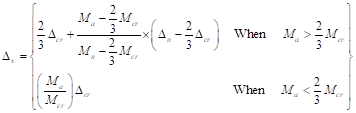 ACI 318-14 (Table 11.8.4.1)
Where Ma is the maximum moment at mid-height of wall due to service lateral and eccentric vertical loads including PΔ effects.
![]()
![]()
![]()
![]() ACI
318-14 (24.2.3.5b)
ACI
318-14 (24.2.3.5b)
![]() ACI
318-14 (11.8.4.3a)
ACI
318-14 (11.8.4.3a)
Δs will be calculated by trial and error method since Δs is a function of Ma and Ma is a function of Δs.
![]()
![]()
![]()
![]() ACI 318-14 (Table 11.8.4.1)
ACI 318-14 (Table 11.8.4.1)
No further iterations are required
![]()
![]()
The wall is adequate with #4 @ 9 in. vertical reinforcement and 8 in. thickness.
spWall is a program for the analysis and design of reinforced concrete shear walls, tilt-up walls, precast walls and Insulate Concrete Form (ICF) walls. It uses a graphical interface that enables the user to easily generate complex wall models. Graphical user interface is provided for:
· Wall geometry (including any number of openings and stiffeners)
· Material properties including cracking coefficients
· Wall loads (point, line, and area),
· Support conditions (including translational and rotational spring supports)
spWall uses the Finite Element Method for the structural modeling, analysis, and design of slender and non-slender reinforced concrete walls subject to static loading conditions. The wall is idealized as a mesh of rectangular plate elements and straight line stiffener elements. Walls of irregular geometry are idealized to conform to geometry with rectangular boundaries. Plate and stiffener properties can vary from one element to another but are assumed by the program to be uniform within each element.
Six degrees of freedom exist at each node: three translations and three rotations relating to the three Cartesian axes. An external load can exist in the direction of each of the degrees of freedom. Sufficient number of nodal degrees of freedom should be restrained in order to achieve stability of the model. The program assembles the global stiffness matrix and load vectors for the finite element model. Then, it solves the equilibrium equations to obtain deflections and rotations at each node. Finally, the program calculates the internal forces and internal moments in each element. At the user’s option, the program can perform second order analysis. In this case, the program takes into account the effect of in-plane forces on the out-of-plane deflection with any number of openings and stiffeners.
In spWall, the required flexural reinforcement is computed based on the selected design standard (ACI 318-14 is used in this example), and the user can specify one or two layers of wall reinforcement. In stiffeners and boundary elements, spWall calculates the required shear and torsion steel reinforcement. Wall concrete strength (in-plane and out-of-plane) is calculated for the applied loads and compared with the code permissible shear capacity.
For illustration and comparison purposes, the following figures provide a sample of the input modules and results obtained from an spWall model created for the reinforced concrete wall in this example.
In this model the following modeling assumptions have been made to closely represent the example in the reference:
1. 5’ wide section of wall is selected to represent the tributary width effective under each of the double tee beam ribs.
2. Idealized continuous wall boundaries using a symmetry support along the vertical edges
3. Pinned the base of the wall assuming support resistance is provided in the X, Y, and Z directions
4. Roller support was used to simulate the diaphragm support provided by the double tee roof beams
5. The load is applied as a single point load under the double tee rib. This can also be applied as a line load or multiple point loads if the complete wall is modeled.
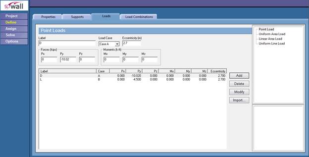
Figure 3 –Defining Loads for Precast Wall Panel (spWall)
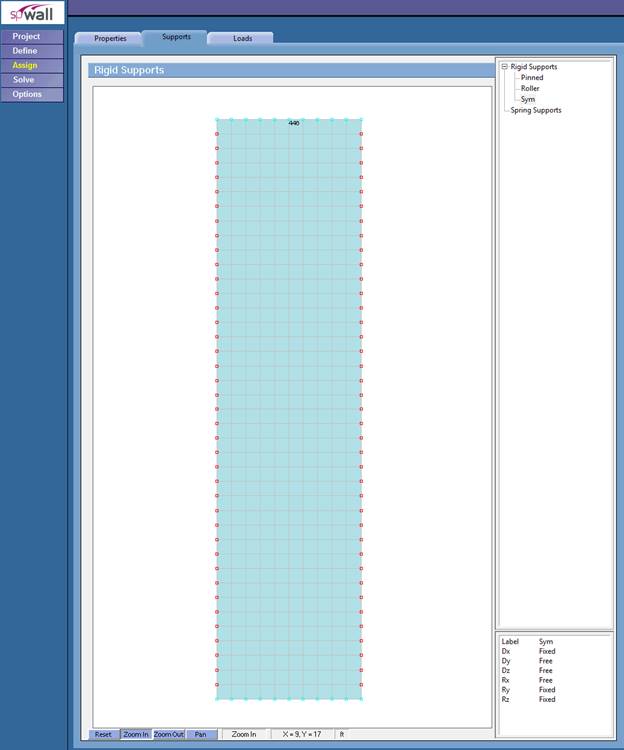
Figure 4 – Assigning Boundary Conditions for Precast Wall Panel (spWall)
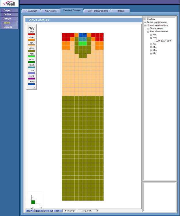
Figure 5 –Factored Axial Forces Contour Normal to Precast Wall Panel Cross-Section (spWall)
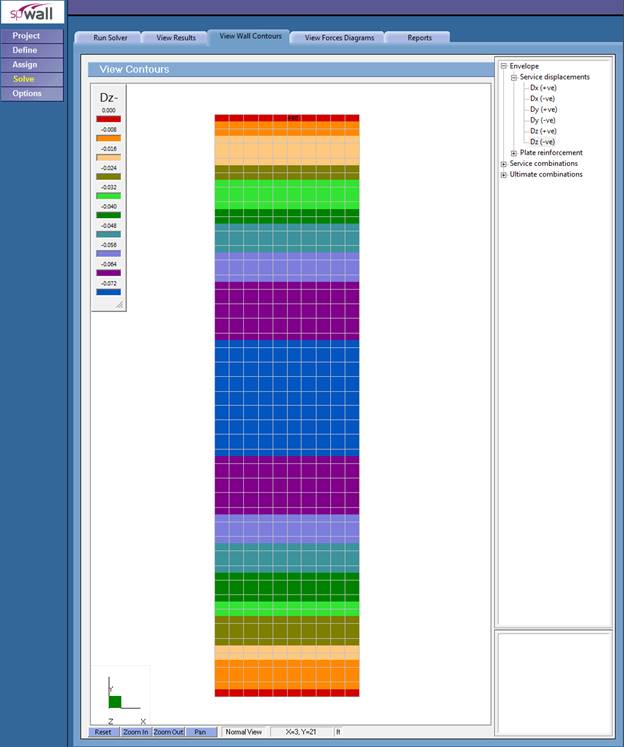
Figure 6 – Precast Wall Panel Lateral Displacement Contour (Out-of-Plane) (spWall)
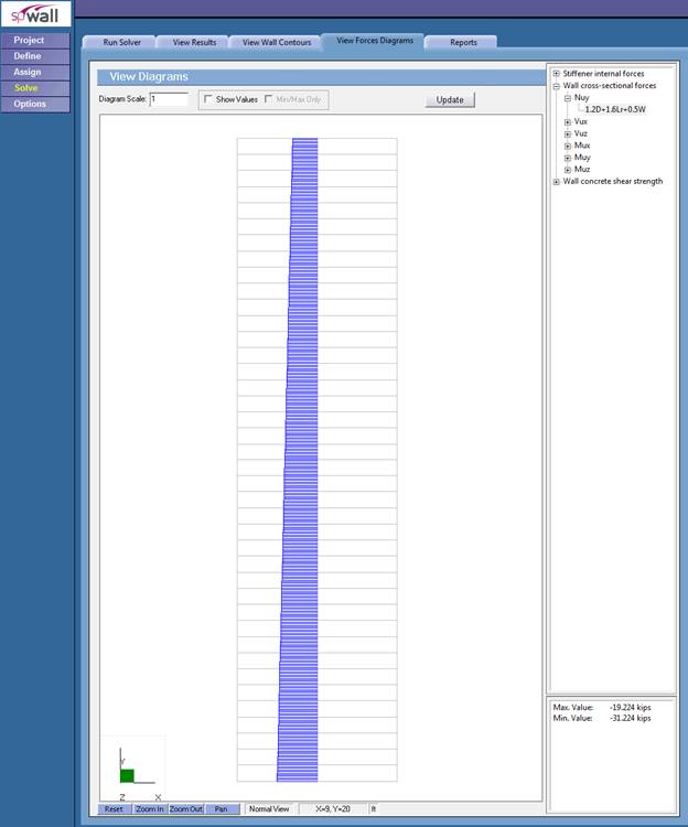
Figure 7 – Precast Wall Panel Axial Load Diagram (spWall)
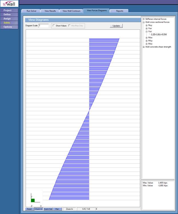
Figure 8 – Out-of-plane Shear Diagram (spWall)
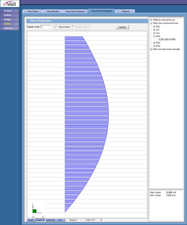
Figure 9 – Shear Wall Moment Diagram (spWall)
![]()
![]()

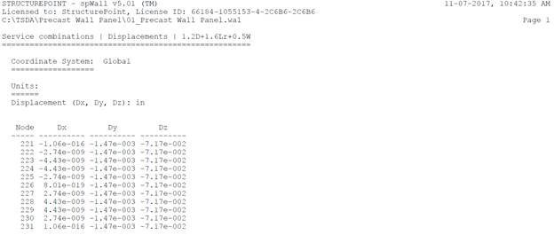
Figure 10 – Precast Wall Panel Vertical Reinforcement (spWall)


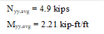

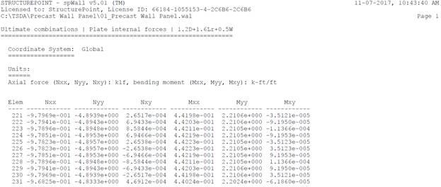
Figure 11 – Precast Wall Panel Cross-Sectional Forces (spWall)
![]()
![]()
![]()
![]()
![]()
![]()
![]()
![]()
![]()
![]()
![]()
![]()
![]()
![]()
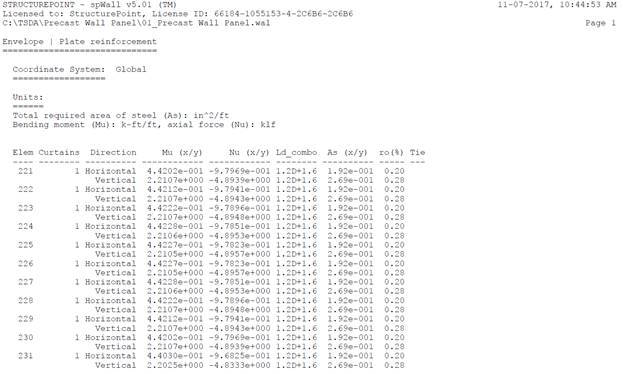
Figure 12 – Precast Wall Panel Required Reinforcement (spWall)
|
Table 3 – Comparison of Precast Wall Panel Analysis and Design Results |
||||
|
Solution |
Mu (kip-ft) |
Nu (kips) |
As,vertical (in.2) |
Dz (in.) |
|
Hand |
2.40 |
5.0 |
0.27 |
0.072 |
|
2.21 |
4.9 |
0.27 |
0.072 |
|
The results of all the hand calculations used illustrated above are in precise agreement with the automated exact results obtained from the spWall program.
In column and wall analysis, section properties shall be determined by taking into account the influence of axial loads, the presence of cracked regions along the length of the member, and the effect of load duration (creep effects). ACI 318 permits the use of moment of inertia values of 0.70 Ig for uncracked walls and 0.35Ig for cracked walls.
ACI 318-14 (6.6.3.1.1)
In spWall program, these effects are accounted for where the user can input reduced moment of inertia using “cracking coefficient” values for plate and stiffener elements to effectively reduce stiffness. Cracking coefficients for out-of-plane (bending and torsion) and in-plane (axial and shear) stiffness can be entered for plate elements. Because the values of the cracking coefficients can have a large effect on the analysis and design results, the user must take care in selecting values that best represent the state of cracking at the particular loading stage. Cracking coefficients are greater than 0 and less than 1.
At ultimate loads, a wall is normally in a highly cracked state. The user could enter a value of out-of-plane cracking coefficient for plates of Icracked/Igross based on estimated values of As. after the analysis and design, if the computed value of As greatly differs from the estimated value of As, the analysis should be performed again with new values for the cracking coefficients.
At service loads, a wall may or may not be in a highly cracked state. For service load deflection analysis, a problem should be modeled with an out-of-plane cracking coefficient for plates of Ieffective/Igross.
Based on the previous discussion, the ratio between Icr and Ig can be used as the cracking coefficient for the out-of-plane case for the ultimate load combinations. In this example, Icr and Ig were found to be equal to 32.5 in.4 and 512 in.4. Thus, the out-of-plane cracking coefficient for ultimate load combinations can be found as follows:
![]()
For the service load combinations, it was found that load combination #2 governs. Ma for this load combination was found to be equal to 21.9 in.-kips which is less than Mcr = 60.7 in.-kips. That means the section is uncracked and the cracking coefficient can be taken equal to 1.
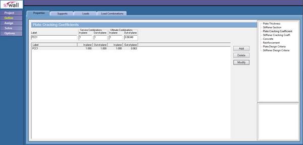
Figure 13 – Defining Cracking Coefficient (spWall)
In spWall, first-order or second-order analysis can be performed to obtain the design moment. In this model, the second order effects were included in order to compare the results with the hand solution results including the PΔ effects.
To further compare the program results with calculations above, the model was run again without the second order effects to compare the moment values with Mua. Table 4 shows the results are also in good agreement.
|
Table 4 - Comparison of Precast Wall Panel First-Order Moments |
||
|
Load Combination |
Mua, in.-kips |
|
|
Hand |
spWall |
|
|
1.4 D |
3.8 |
4.3 |
|
1.2 D + 1.6 Lr + 0.8 W |
19.2 |
20.0 |
|
1.2 D + 0.5 Lr +1.6 W |
32.4 |
32.7 |
|
0.9 D + 1.6 W |
31.2 |
31.1 |
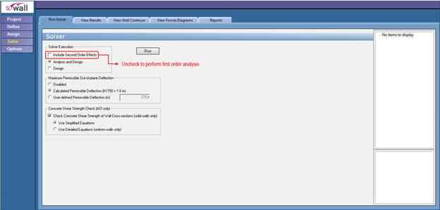
Figure 14 – Solver Module (spWall)