Code
Building Code Requirements
for Structural Concrete (ACI 318-14) and Commentary (ACI 318R-14)
Minimum Design Loads for
Buildings and Other Structures (ASCE/SEI 7-10)
International Code Council,
2012 International Building Code, Washington, D.C., 2012
References
Notes on ACI 318-11 Building
Code Requirements for Structural Concrete, Twelfth Edition, 2013 Portland
Cement Association.
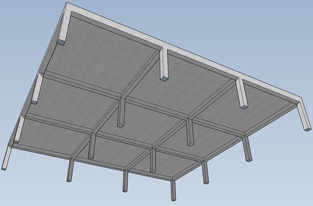
Concrete Floor Systems
(Guide to Estimating and Economizing), Second Edition, 2002 David A. Fanella
Simplified Design of
Reinforced Concrete Buildings, Fourth Edition, 2011 Mahmoud E. Kamara and
Lawrence C. Novak
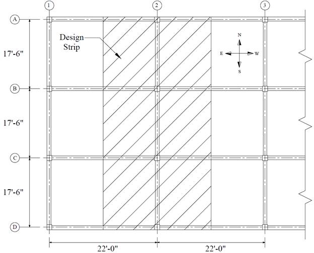
Design Data
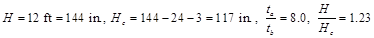
Floor-to-Floor Height = 12
ft (provided by architectural drawings)
Columns = 18 x 18 in.
Interior beams = 14 x 20 in.
Edge beams = 14 x 27 in.
wc = 150 pcf
fc’ =
4,000 psi
fy = 60,000 psi
Live load, Lo
= 100 psf (Office building) ASCE/SEI
7-10 (Table 4-1)
Solution
Control of deflections. ACI
318-14 (8.3.1.2)
In lieu of detailed calculation for deflections, ACI 318 Code
gives minimum thickness for two-way slab with beams spanning between supports
on all sides in Table 8.3.1.2.
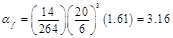
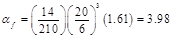
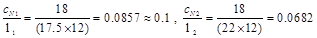
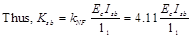
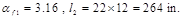
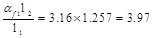
Beam-to-slab flexural stiffness
(relative stiffness) ratio (αf) is computed as follows:
 ACI
318-14 (8.10.2.7b)
ACI
318-14 (8.10.2.7b)
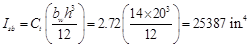
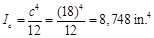
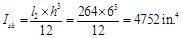
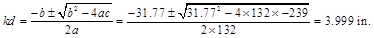
The moment of inertia for the
effective beam and slab sections can be calculated as follows:
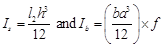
Then,

For Edge Beams:
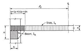
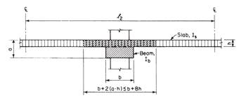
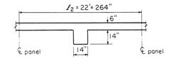
The effective beam and slab sections for the computation of
stiffness ratio for edge beam is shown in Figure 2.
For North-South Edge Beam:


 For East-West
Edge Beam:
For East-West
Edge Beam:


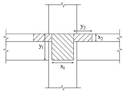
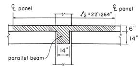
For interior Beams:
The effective beam and slab sections for the computation of
stiffness ratio for interior beam is shown in Figure 4.
For North-South Interior Beam:


 For East-West
Interior Beam:
For East-West
Interior Beam:

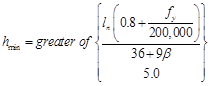
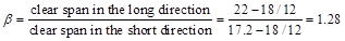
Since αf > 2.0 for
all beams, the minimum slab thickness is given by:
 ACI
318-14 (8.3.1.2)
ACI
318-14 (8.3.1.2)
Where:

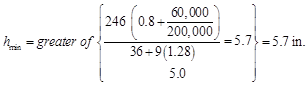
Use 6 in. slab thickness.
ACI 318 states that a slab system
shall be designed by any procedure satisfying equilibrium and geometric
compatibility, provided that strength and serviceability criteria are
satisfied. Distinction of two-systems from one-way systems is given by ACI
318-14 (R8.10.2.3 & R8.3.1.2).
ACI 318 permits the use of Direct
Design Method (DDM) and Equivalent Frame Method (EFM) for the gravity load
analysis of orthogonal frames and is applicable to flat plates, flat slabs, and
slabs with beams. The following sections outline the solution per EFM and spSlab software. The solution per DDM can
be found in the “Two-Way Plate Concrete Floor System Design” example.
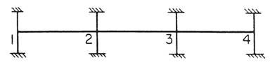
EFM is the most comprehensive and
detailed procedure provided by the ACI 318 for the analysis and design of
two-way slab systems where the structure is modeled by a series of equivalent
frames (interior and exterior) on column lines taken longitudinally and
transversely through the building.
The equivalent frame consists of three
parts:
1) Horizontal slab-beam strip, including
any beams spanning in the direction of the frame. Different values of moment of
inertia along the axis of slab-beams should be taken into account where the
gross moment of inertia at any cross section outside of joints or column
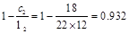
capitals shall be taken, and the moment of inertia of the slab-beam at the
face of the column, bracket or capital divide by the quantity (1-c2/l2)2
shall be assumed for the calculation of the moment of inertia of slab-beams
from the center of the column to the face of the column, bracket or capital. ACI
318-14 (8.11.3)
2) Columns or other vertical supporting
members, extending above and below the slab. Different values of moment of
inertia along the axis of columns should be taken into account where the moment
of inertia of columns from top and bottom of the slab-beam at a joint shall be
assumed to be infinite, and the gross cross section of the concrete is
permitted to be used to determine the moment of inertia of columns at any cross
section outside of joints or column capitals. ACI
318-14 (8.11.4)
3) Elements of the structure (Torsional
members) that provide moment transfer between the horizontal and vertical
members. These elements shall be assumed to have a constant cross section
throughout their length consisting of the greatest of the following: (1)
portion of slab having a width equal to that of the column, bracket, or capital
in the direction of the span for which moments are being determined, (2)
portion of slab specified in (1) plus that part of the transverse beam above
and below the slab for monolithic or fully composite construction, (3) the
transverse beam includes that portion of slab on each side of the beam
extending a distance equal to the projection of the beam above or below the
slab, whichever is greater, but not greater than four times the slab thickness. ACI
318-14 (8.11.5)
In
EFM, live load shall be arranged in accordance with 6.4.3 which requires slab
systems to be analyzed and designed for the most demanding set of forces
established by investigating the effects of live load placed in various
critical patterns. ACI 318-14 (8.11.1.2 & 6.4.3)
Complete
analysis must include representative interior and exterior equivalent frames in
both the longitudinal and transverse directions of the floor. ACI 318-14 (8.11.2.1)
Panels shall
be rectangular, with a ratio of longer to shorter panel dimensions, measured
center-to-center of supports, not to exceed 2. ACI 318-14 (8.10.2.3)
Determine moment distribution factors and fixed-end
moments for the equivalent frame members. The moment distribution procedure
will be used to analyze the equivalent frame. Stiffness factors  , carry over factors COF, and fixed-end moment factors
FEM for the slab-beams and column members are determined using the design aids tables
at Appendix 20A of PCA Notes on ACI 318-11. These
calculations are shown below.
, carry over factors COF, and fixed-end moment factors
FEM for the slab-beams and column members are determined using the design aids tables
at Appendix 20A of PCA Notes on ACI 318-11. These
calculations are shown below.
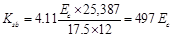
a.
Flexural
stiffness of slab-beams at both ends, Ksb.
 PCA Notes on ACI 318-11 (Table A1)
 PCA Notes on ACI 318-11 (Table A1)

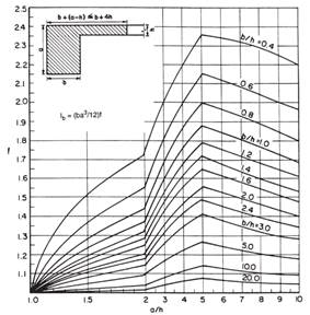
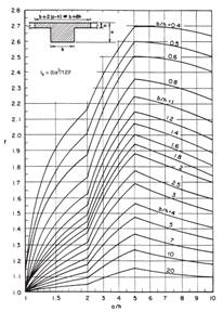
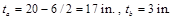
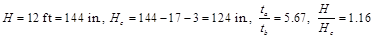
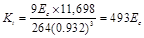
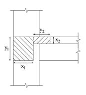
 Where Isb
is the moment of inertia of slab-beam section shown in Figure 6 and can be
computed with the aid of Figure 7 as follows:
Where Isb
is the moment of inertia of slab-beam section shown in Figure 6 and can be
computed with the aid of Figure 7 as follows:
Carry-over factor COF = 0.507 PCA
Notes on ACI 318-11 (Table A1)
 PCA
Notes on ACI 318-11 (Table A1)
PCA
Notes on ACI 318-11 (Table A1)
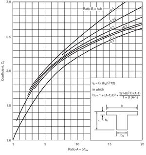
Figure 7 –
Coefficient Ct for Gross Moment of Inertia of Flanged Sections
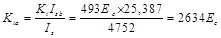
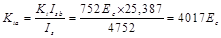
b.
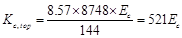
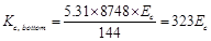
Flexural
stiffness of column members at both ends, Kc.
Referring to Table
A7, Appendix 20A:
For Interior
Columns:


 PCA
Notes on ACI 318-11 (Table A7)
PCA
Notes on ACI 318-11 (Table A7)
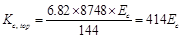
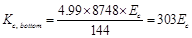
For Exterior Columns:


PCA
Notes on ACI 318-11 (Table A7)
c.
Torsional stiffness
of torsional members, Kt.
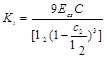 ACI 318-14 (R.8.11.5)
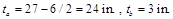
For
Interior Columns:
Where:
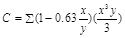 ACI 318-14 (Eq. 8.10.5.2b)
|
x1
= 14 in
|
x2
= 6 in
|
x1
= 14 in
|
x2
= 6 in
|
|
y1
= 14 in
|
y2
= 42 in
|
y1
= 20 in
|
y2
= 14 in
|
|
C1
= 4738
|
C2
= 2,752
|
C1
= 10,226
|
C2
= 736
|
|
∑C
= 4738 + 2,752 = 7,490 in4
|
∑C
= 10,226 + 736 x 2 = 11,698 in4
|
|
|
|
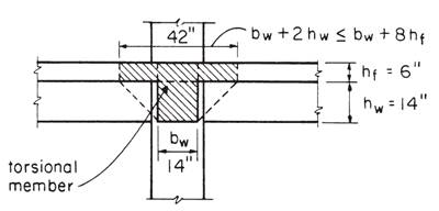
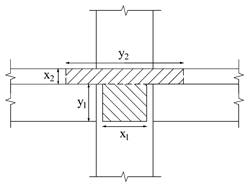
Figure 8 –
Attached Torsional Member at Interior Column
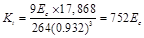
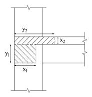
For Exterior
Columns:
Where:
ACI 318-14 (Eq. 8.10.5.2b)
|
x1
= 14 in
|
x2
= 6 in
|
x1
= 14 in
|
x2
= 6 in
|
|
y1
= 21 in
|
y2
= 35 in
|
y1
= 27 in
|
y2
= 21 in
|
|
C1
= 11,141
|
C2
= 2,248
|
C1
= 16,628
|
C2
= 1,240
|
|
∑C
= 11,141 + 2,248 = 13,389 in4
|
∑C
= 16,628 + 1,240 = 17,868 in4
|
|
|
|
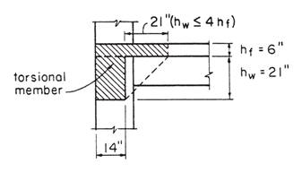
Figure 9 –
Attached Torsional Member at Exterior Column
d. Increased torsional stiffness due to
parallel beams, Kta.
For Interior Columns:
Where:
For Exterior Columns:

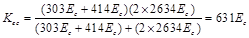
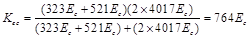
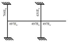
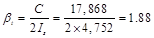
e.
Equivalent column
stiffness Kec.
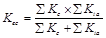
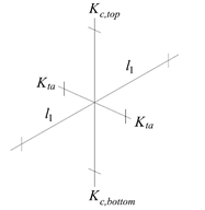 Where ∑ Kta is for two torsional members one on each side of the column, and ∑ Kc is for the upper and lower columns at the slab-beam joint of an
intermediate floor.
Where ∑ Kta is for two torsional members one on each side of the column, and ∑ Kc is for the upper and lower columns at the slab-beam joint of an
intermediate floor.
For Interior Columns:
For Exterior Columns:
f. Slab-beam joint distribution factors,
DF.
At exterior joint,
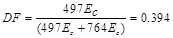
At
interior joint,
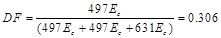

 COF for slab-beam =0.507
Determine
negative and positive moments for the slab-beams using the moment distribution
method.
With
an unfactored live-to-dead load ratio:
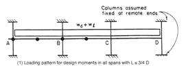
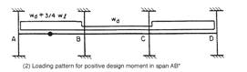
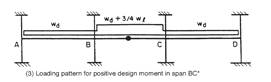
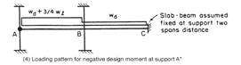
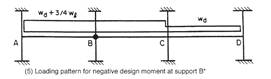
The frame will be analyzed
for five loading conditions with pattern loading and partial live load as
allowed by ACI 318-14 (6.4.3.3).
a.
Factored load and
Fixed-End Moments (FEM’s).

Where (9.3 psf = (14 x 14) /
144 x 150 / 22 is the weight of beam stem per foot divided by l2)


 PCA Notes on ACI 318-11 (Table A1)


b. Moment distribution.
Moment distribution for the five
loading conditions is shown in Table 1. Counter-clockwise rotational moments
acting on member ends are taken as positive. Positive span moments are
determined from the following equation:
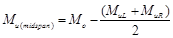
Where
Mo is the moment at the midspan for a simple beam.
When
the end moments are not equal, the maximum moment in the span does not occur at
the midspan, but its value is close to that midspan for this example.
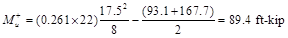
Positive
moment in span 1-2 for loading (1):
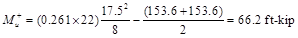
Positive moment span 2-3 for loading
(1):
|
Table 1 – Moment
Distribution for Partial Frame (Transverse Direction)
|
|
Joint
|
1
|
2
|
3
|
4
|

|
|
Member
|
1-2
|
2-1
|
2-3
|
3-2
|
3-4
|
4-3
|
|
DF
|
0.394
|
0.306
|
0.306
|
0.306
|
0.306
|
0.394
|
|
COF
|
0.507
|
0.507
|
0.507
|
0.507
|
0.507
|
0.507
|
|
Loading (1) All
spans loaded with full factored live load
|
|
FEM
|
148.1
|
-148.1
|
148.1
|
-148.1
|
148.1
|
-148.1
|
|
|
Dist
|
-58.4
|
0
|
0
|
0
|
0
|
58.4
|
|
CO
|
0
|
-29.6
|
0
|
0
|
29.6
|
0
|
|
Dist
|
0
|
9.1
|
9.1
|
-9.1
|
-9.1
|
0
|
|
CO
|
4.6
|
0
|
-4.6
|
4.6
|
0
|
-4.6
|
|
Dist
|
-1.8
|
1.4
|
1.4
|
-1.4
|
-1.4
|
1.8
|
|
CO
|
0.7
|
-0.9
|
-0.7
|
0.7
|
0.9
|
-0.7
|
|
Dist
|
-0.3
|
0.5
|
0.5
|
-0.5
|
-0.5
|
0.3
|
|
CO
|
0.3
|
-0.1
|
-0.3
|
0.3
|
0.1
|
-0.3
|
|
Dist
|
-0.1
|
0.1
|
0.1
|
-0.1
|
-0.1
|
0.1
|
|
M
|
93.1
|
-167.6
|
153.6
|
-153.6
|
167.6
|
-93.1
|
|
Midspan M
|
89.5
|
66.2
|
89.5
|
|
Loading (2)
First and third spans loaded with 3/4 factored live load
|
|
FEM
|
125.4
|
-125.4
|
57.3
|
-57.3
|
125.4
|
-125.4
|
|
|
Dist
|
-49.4
|
20.8
|
20.8
|
-20.8
|
-20.8
|
49.4
|
|
CO
|
10.6
|
-25.1
|
-10.6
|
10.6
|
25.1
|
-10.6
|
|
Dist
|
-4.2
|
10.9
|
10.9
|
-10.9
|
-10.9
|
4.2
|
|
CO
|
5.5
|
-2.1
|
-5.5
|
5.5
|
2.1
|
-5.5
|
|
Dist
|
-2.2
|
2.3
|
2.3
|
-2.3
|
-2.3
|
2.2
|
|
CO
|
1.2
|
-1.1
|
-1.2
|
1.2
|
1.1
|
-1.2
|
|
Dist
|
-0.5
|
0.7
|
0.7
|
-0.7
|
-0.7
|
0.5
|
|
CO
|
0.4
|
-0.2
|
-0.4
|
0.4
|
0.2
|
-0.4
|
|
Dist
|
-0.1
|
0.2
|
0.2
|
-0.2
|
-0.2
|
0.1
|
|
M
|
86.7
|
-119
|
74.5
|
-74.5
|
119
|
-86.7
|
|
Midspan M
|
83.3
|
10.6
|
83.3
|
|
Loading (3)
Center span loaded with 3/4 factored live load
|
|
FEM
|
57.3
|
-57.3
|
125.4
|
-125.4
|
57.3
|
-57.3
|
|
|
Dist
|
-22.6
|
-20.8
|
-20.8
|
20.8
|
20.8
|
22.6
|
|
CO
|
-10.6
|
-11.4
|
10.6
|
-10.6
|
11.4
|
10.6
|
|
Dist
|
4.2
|
0.3
|
0.3
|
-0.3
|
-0.3
|
-4.2
|
|
CO
|
0.1
|
2.1
|
-0.1
|
0.1
|
-2.1
|
-0.1
|
|
Dist
|
-0.1
|
-0.6
|
-0.6
|
0.6
|
0.6
|
0.1
|
|
CO
|
-0.3
|
0
|
0.3
|
-0.3
|
0
|
0.3
|
|
Dist
|
0.1
|
-0.1
|
-0.1
|
0.1
|
0.1
|
-0.1
|
|
CO
|
0
|
0.1
|
0
|
0
|
-0.1
|
0
|
|
Dist
|
0
|
0
|
0
|
0
|
0
|
0
|
|
M
|
28.1
|
-87.7
|
115
|
-115
|
87.7
|
-28.1
|
|
Midspan M
|
27.2
|
71.3
|
27.2
|
|
Loading (4)
First span loaded with 3/4 factored live load and beam-slab assumed fixed at
support two spans away
|
|
FEM
|
125.4
|
-125.4
|
57.3
|
-57.3
|
|
|
|
Dist
|
-49.4
|
20.8
|
20.8
|
0
|
|
CO
|
10.6
|
-25
|
0
|
10.6
|
|
Dist
|
-4.2
|
7.7
|
7.7
|
0
|
|
CO
|
3.9
|
-2.1
|
0
|
3.9
|
|
Dist
|
-1.5
|
0.6
|
0.6
|
0
|
|
CO
|
0.3
|
-0.8
|
0
|
0.3
|
|
Dist
|
-0.1
|
0.2
|
0.2
|
0
|
|
CO
|
0.1
|
-0.1
|
0
|
0.1
|
|
Dist
|
0
|
0
|
0
|
0
|
|
M
|
85.1
|
-124.1
|
86.6
|
-42.4
|
|
Midspan M
|
81.5
|
20.6
|
|
Loading (5)
First and second spans loaded with 3/4 factored live load
|
|
FEM
|
125.4
|
-125.4
|
125.4
|
-125.4
|
57.3
|
-57.3
|
|
|
Dist
|
-49.4
|
0.0
|
0.0
|
20.8
|
20.8
|
22.6
|
|
CO
|
0.0
|
-25.1
|
10.6
|
0.0
|
11.4
|
10.6
|
|
Dist
|
0.0
|
4.4
|
4.4
|
-3.5
|
-3.5
|
-4.2
|
|
CO
|
2.2
|
0.0
|
-1.8
|
2.2
|
-2.1
|
-1.8
|
|
Dist
|
-0.9
|
0.5
|
0.5
|
0.0
|
0.0
|
0.7
|
|
CO
|
0.3
|
-0.4
|
0.0
|
0.3
|
0.4
|
0.0
|
|
Dist
|
-0.1
|
0.1
|
0.1
|
-0.2
|
-0.2
|
0.0
|
|
CO
|
0.1
|
-0.1
|
-0.1
|
0.1
|
0.0
|
-0.1
|
|
Dist
|
0.0
|
0.0
|
0.0
|
0.0
|
0.0
|
0.0
|
|
M
|
77.6
|
-146.0
|
139.1
|
-105.7
|
84.1
|
-29.5
|
|
Midspan M
|
74.3
|
63.7
|
28.3
|
|

|
|
|
Max M-
|
93.1
|
-167.7
|
153.6
|
-153.6
|
167.7
|
-93.1
|
|
Max M+
|
89.4
|
71.3
|
89.4
|
Positive and negative factored
moments for the slab system in the direction of analysis are plotted in Figure
13. The negative design moments are taken at the faces of rectilinear supports
but not at distances greater than  from the centers of supports. ACI
318-14 (8.11.6.1)
from the centers of supports. ACI
318-14 (8.11.6.1)
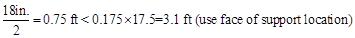
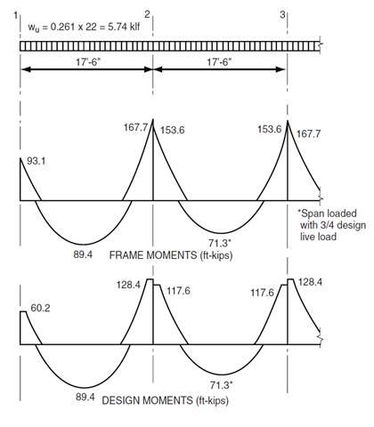
Figure 13 – Positive and Negative Design Moments for
Slab-Beam (All Spans Loaded with Full Factored Live Load Except as Noted)
a. Check whether the moments calculated
above can take advantage of the reduction permitted by ACI 318-14 (8.11.6.5):
Slab systems within the limitations
of ACI 318-14 (8.10.2) may have the resulting reduced in
such proportion that the numerical sum of the positive and average negative
moments not be greater than the total static moment Mo given
by Equation 8.10.3.2 in the ACI 318-14:
ACI 318-14 (8.11.6.5)
Check Applicability of Direct Design
Method:
1.
There is a
minimum of three continuous spans in each direction ACI
318-14 (8.10.2.1)
2.
Successive span
lengths are equal ACI
318-14 (8.10.2.2)
3.
Long-to-Short
ratio is 22/17.5 = 1.26 < 2.0 ACI
318-14 (8.10.2.3)
4.
Column are not
offset ACI
318-14 (8.10.2.4)
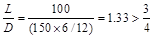
5.
Loads are gravity
and uniformly distributed with service live-to-dead ratio of 1.33 < 2.0
ACI
318-14 (8.10.2.5 and 6)
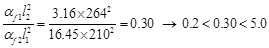
6. Check relative stiffness for slab panel: ACI
318-14 (8.10.2.7)
Interior Panel:

 O.K. ACI 318-14
(Eq. 8.10.2.7a)
O.K. ACI 318-14
(Eq. 8.10.2.7a)
Interior Panel:

 O.K. ACI 318-14
(Eq. 8.10.2.7a)
O.K. ACI 318-14
(Eq. 8.10.2.7a)
All limitation of ACI
318-14 (8.10.2) are satisfied and the provisions of ACI
318-14 (8.11.6.5) may be applied:
 ACI
318-14 (Eq. 8.10.3.2)
ACI
318-14 (Eq. 8.10.3.2)


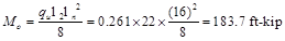
To
illustrate proper procedure, the interior span factored moments may be reduced
as follows:
Permissible
reduction = 183.7/188.8 = 0.973
Adjusted negative design
moment = 117.6 × 0.973 = 114.3 ft-kip
Adjusted positive design
moment = 71.2 × 0.973 = 69.3 ft-kip
Mo = 183.7 ft-kip
b. Distribute factored moments to column
and middle strips:
The negative and positive factored moments at critical
sections may be distributed to the column strip and the two half-middle strips
of the slab-beam according to the Direct Design Method (DDM) in 8.10, provided
that Eq. 8.10.2.7(a) is satisfied. ACI
318-14 (8.11.6.6)
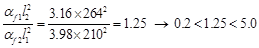
Since the relative stiffness of beams are between 0.2
and 5.0 (see step 2.4.1.6), the moments can be distributed across slab-beams as
specified in ACI 318-14 (8.10.5 and 6) where:


Factored moments at critical
sections are summarized in Table 2.
|
Table 2 - Lateral
distribution of factored moments
|
|
Factored Moments
(ft-kips)
|
Column Strip
|
Moments in Two
Half-Middle Strips**
(ft-kips)
|
|
Percent*
|
Moment
(ft-kips)
|
Beam Strip
Moment
(ft-kips)
|
Column Strip
Moment
(ft-kips)
|
|
End
Span
|
Exterior Negative
|
60.2
|
75
|
45.2
|
38.4
|
6.8
|
15
|
|
Positive
|
89.4
|
67
|
59.9
|
50.9
|
9.0
|
29.5
|
|
Interior Negative
|
128.4
|
67
|
86
|
73.1
|
12.9
|
42.4
|
|
Interior
Span
|
Negative
|
117.6
|
67
|
78.8
|
67.0
|
11.8
|
38.8
|
|
Positive
|
71.3
|
67
|
47.8
|
40.6
|
7.2
|
23.5
|
|
*Since α1l2/l1 >
1.0 beams must be proportioned to resist 85 percent of column strip per ACI
318-14 (8.10.5.7)
|
|
**That portion of the factored moment not resisted by the
column strip is assigned to the two half-middle strips
|
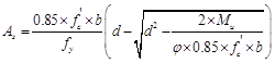
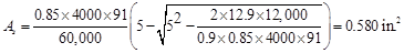
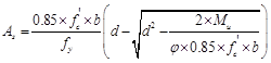
a. Determine flexural reinforcement required for strip
moments
The flexural reinforcement
calculation for the column strip of end span – interior negative location is
provided below:

Assume tension-controlled
section (φ = 0.9)
Column strip width, b
= (17.5 x 12) / 2 = 91 in.
Use average d = 6 –
0.75 – 0.5/2 = 5 in.
 in2
in2

Maximum spacing  ACI
318-14 (8.7.2.2)
ACI
318-14 (8.7.2.2)
Provide 8 - #4 bars with As
= 1.60 in.2 and s =
91/8 = 11.37 in. ≤ smax
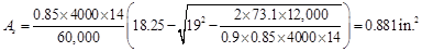
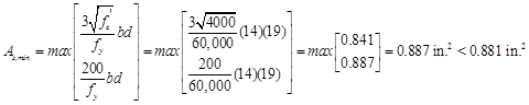
The
flexural reinforcement calculation for the beam strip of end span – interior
negative location is provided below:

Assume tension-controlled
section (φ = 0.9)
Beam strip width, b =
14 in.
Use average d = 20 –
0.75 – 0.5/2 = 19 in.

Provide 5 - #4 bars with As
= 1.00 in.2
All the values on Table 3 are
calculated based on the procedure outlined above.
|
Table 3 -
Required Slab Reinforcement for Flexure [Equivalent Frame Method (EFM)]
|
|
|
Span
Location
|
Mu
(ft-kip)
|
b *
(in.)
|
d **
(in.)
|
As Req’d
for flexure
(in.2)
|
Min As†
††
(in.2)
|
Reinforcement
Provided
|
As Prov.
for flexure
(in.2)
|
|
|
|
End Span
|
|
|
Beam Strip
|
Exterior Negative
|
38.4
|
14
|
19.00
|
0.456
|
0.608
|
4 - #4
|
0.8
|
|
|
Positive
|
50.9
|
14
|
18.25
|
0.634
|
0.852
|
5 - #4
|
1.0
|
|
|
Interior Negative
|
73.1
|
14
|
19.00
|
0.881
|
0.887
|
5 - #4
|
1.0
|
|
|
Column Strip
|
Exterior Negative
|
6.8
|
91
|
5.00
|
0.304
|
0.983
|
8 - #4
|
1.6
|
|
|
Positive
|
9.0
|
91
|
5.00
|
0.403
|
0.983
|
8 - #4
|
1.6
|
|
|
Interior Negative
|
12.9
|
91
|
5.00
|
0.580
|
0.983
|
8 - #4
|
1.6
|
|
|
Middle Strip
|
Exterior Negative
|
15.0
|
159
|
5.00
|
0.672
|
1.717
|
14 - #4
|
2.8
|
|
|
Positive
|
29.5
|
159
|
5.00
|
1.331
|
1.717
|
14 - #4
|
2.8
|
|
|
Interior Negative
|
42.4
|
159
|
5.00
|
1.926
|
1.717
|
14 - #4
|
2.8
|
|
|
Interior
Span
|
|
|
Beam Strip
|
Positive
|
40.6
|
14
|
18.25
|
0.503
|
0.671
|
4 - #4
|
0.8
|
|
|
Column Strip
|
Positive
|
7.2
|
91
|
5.00
|
0.322
|
0.983
|
8 - #4
|
1.6
|
|
|
Middle Strip
|
Positive
|
23.5
|
159
|
5.00
|
1.057
|
1.717
|
14 - #4
|
2.8
|
|
|
* Column strip width, b = (17.5 × 12)/2 - 14 = 91 in.
|
|
|
* Middle strip width, b = 22*12-(17.5*12)/2 = 159 in.
|
|
|
* Beam strip width, b = 14 in.
|
|
|
** Use average d = 6 – 0.75 – 0.5/2 = 5.00 in. for Column
and Middle strips
|
|
|
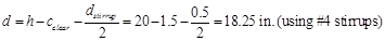
** Use average d = 20 - 1.5 - 0.5/2 = 18.25 in. for Beam
strip Positive moment regions
|
|
|
** Use average d = 20 - 0.75 - 0.5/2 = 19 in. for Beam strip
Negative moment regions
|
|
|
† Min. As = 0.0018 × b × h = 0.0108 × b for
Column and Middle
strips ACI 318-14
(7.6.1.1)
|
|
|
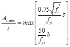
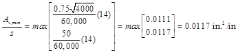
† Min. As = min (3(fc')^0.5/fy*b*d
, 200/fy*b*d) for Beam
strip ACI
318-14 (9.6.1.2)
|
|
|
†† Min. As = 1.333 × As Req'd if As provided
>= 1.333 × As Req'd for Beam strip ACI
318-14 (9.6.1.3)
|
|
|
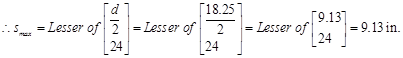
smax = 2 × h = 12 in. < 18
in.
ACI 318-14 (8.7.2.2)
|
|
b.
Calculate additional slab reinforcement at columns for moment transfer between slab
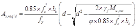
and column by flexure
Portion of the unbalanced
moment transferred by flexure is γf x Mu
Where:
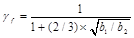 ACI 318-14 (8.4.2.3.2)
b1 = Dimension of the critical section bo
measured in the direction of the span for which
moments are determined in ACI 318, Chapter 8.
b2 = Dimension of the critical section bo
measured in the direction perpendicular to b1
in ACI 318, Chapter 8.
bo
= Perimeter of critical section for two-way
shear in slabs and footings.
 ACI
318-14 (8.4.2.3.3)
ACI
318-14 (8.4.2.3.3)
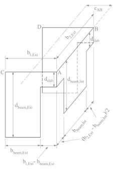
For Exterior Column:

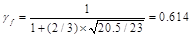

Figure 14 – Critical Shear Perimeters for Columns

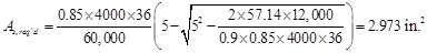


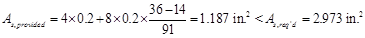
 Additional slab reinforcement at the exterior column
is required.
Additional slab reinforcement at the exterior column
is required.


|
Table 4 -
Additional Slab Reinforcement at columns for moment transfer between slab and
column [Equivalent Frame Method (EFM)]
|
|
Span
Location
|
Effective
slab width, bb (in.)
|
d
(in.)
|
γf
|
Mu*
(ft-kip)
|
γf
Mu
(ft-kip)
|
As
req’d within bb (in.2)
|
As
prov. for
flexure
within bb (in.2)
|
Add’l Reinf.
|
|
End Span
|
|
Column Strip
|
Exterior
Negative
|
36
|
5
|
0.614
|
93.1
|
57.14
|
2.973
|
1.187
|
10-#4
|
|
Interior
Negative
|
36
|
5
|
0.600
|
44.5
|
26.70
|
1.265
|
1.387
|
-
|
|
*Mu is taken at the centerline
of the support in Equivalent Frame Method solution.
|
b. Determine
transverse reinforcement required for beam strip shear
The
transverse reinforcement calculation for the beam strip of end span – exterior
location is provided below.
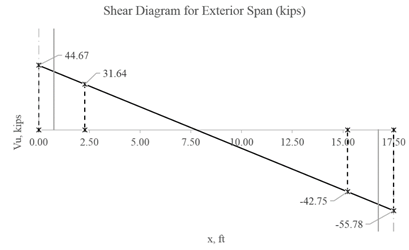
Figure 15 – Shear at critical sections for the end
span (at distance d from the face of the column)
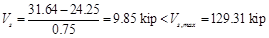
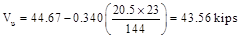
The required shear at a
distance d from the face of the supporting column Vu_d= 31.64
kips (Figure 15).
 ACI
318-14 (22.5.5.1)
ACI
318-14 (22.5.5.1)
 ∴
Stirrups are required.
∴
Stirrups are required.
Distance from the column face
beyond which minimum reinforcement is required:
 ACI
318-14 (22.5.10.1)
ACI
318-14 (22.5.10.1)
 O.K.
O.K.
 ACI 318-14 (22.5.10.1)
 ACI
318-14 (22.5.10.5.3)
ACI
318-14 (22.5.10.5.3)
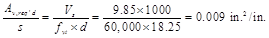
 ACI
318-14 (9.6.3.3)
ACI
318-14 (9.6.3.3)

 ACI 318-14 (9.7.6.2.2)

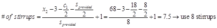
Select
sprovided = 8 in. #4 stirrups with first stirrup located at
distance 3 in. from the column face.
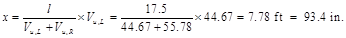
The
distance where the shear is zero is calculated as follows:
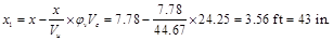
The
distance from support beyond which minimum reinforcement is required is
calculated as follows:
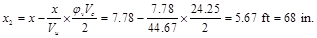
The
distance at which no shear reinforcement is required is calculated as follows:
All
the values on Table 5 are calculated based on the procedure outlined above.
|
Table 5 - Required Beam
Reinforcement for Shear
|
|
Span Location
|
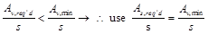
Av,min/s
in2/in
|
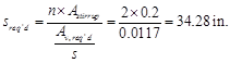
Av,req'd/s
in2/in
|
sreq'd
in
|
smax
in
|
Reinforcement
Provided
|
|
End Span
|
|
Exterior
|
0.0117
|
0.0090
|
34.28
|
9.13
|
8 - #4 @ 8 in*
|
|
Interior
|
0.0117
|
0.0225
|
17.76
|
9.13
|
10 - #4 @ 8.6 in
|
|
Interior Span
|
|
Interior
|
0.0117
|
0.0158
|
25.37
|
9.13
|
9 - #4 @ 8.6 in
|
|
* Minimum
transverse reinforcement governs
|
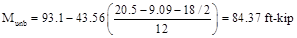
The
unbalanced moment from the slab-beams at the supports of the equivalent frame
are distributed to the actual columns above and below the slab-beam in
proportion to the relative stiffness of the actual columns. Referring to Fig.
9, the unbalanced moment at joints 1 and 2 are:
Joint
1 = +93.1 ft-kip
Joint
2 = -119 + 74.5 = -44.5 ft-kip
The
stiffness and carry-over factors of the actual columns and the distribution of
the unbalanced moments to the exterior and interior columns are shown in Fig 9.
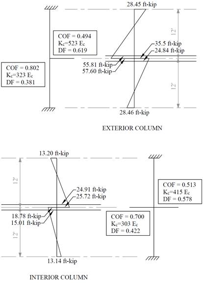
Figure 16 - Column Moments (Unbalanced Moments from
Slab-Beam)
In summary:
Design moment in exterior
column = 55.81 ft-kip
Design
moment in interior column = 24.91 ft-kip
The
moments determined above are combined with the factored axial loads (for each
story) and factored moments in the transverse direction for design of column
sections. A detailed analysis to obtain the moment values at the face of
interior, exterior, and corner columns from the unbalanced moment values can be
found in the “Two-Way Flat Plate Concrete Floor Slab Design” example.
The design of
interior, edge, and corner columns is explained in the “Two-Way Flat Plate Concrete Floor Slab Design” example.
Shear strength of the slab in the vicinity
of columns/supports includes an evaluation of one-way shear (beam action) and
two-way shear (punching) in accordance with ACI 318 Chapter 22.
One-way shear is critical at
a distance d from the face of the column. Figure 17 shows the Vu at
the critical sections around each column. Since there is no shear
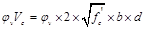
reinforcement, the design shear capacity of the section equals to the design
shear capacity of the concrete:
 ACI 318-14 (Eq. 22.5.1.1)
Where:
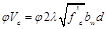 ACI 318-14 (Eq. 22.5.5.1)
λ = 1 for normal weight concrete
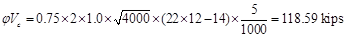
Because φVc
> Vu at all the
critical sections, the slab is o.k. in one-way shear.
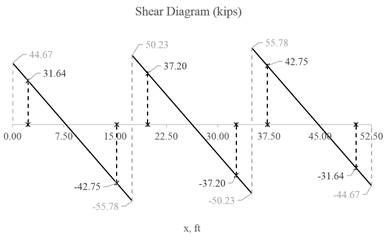
Figure 17 – One-way shear at critical sections (at
distance d from the face of the supporting column)
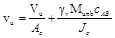
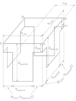
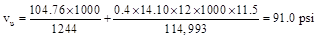
Two-way shear is critical on a rectangular section
located at dslab/2 away from the face of the column. The
factored shear force Vu in the critical section is calculated
as the reaction at the centroid of the critical section minus the self-weight
and any superimposed surface dead and live load acting within the critical
section.
The factored unbalanced moment used for shear
transfer, Munb, is calculated as the sum of the joint moments
to the left and right. Moment of the vertical reaction with respect to the
centroid of the critical section is also taken into account.
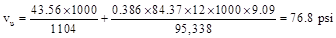
 For the exterior column:
For
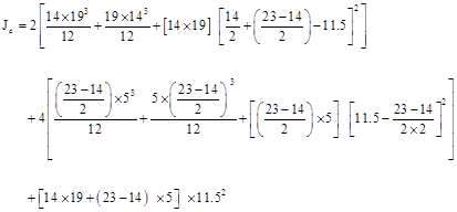
the exterior column in Figure 18, the location of the centroidal axis z-z is:
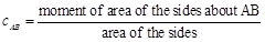
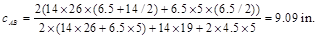

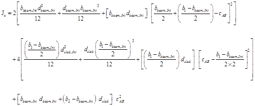
The polar moment Jc of the shear perimeter
is:
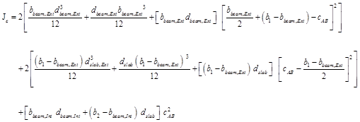
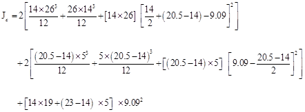

 ACI 318-14 (Eq. 8.4.4.2.2)
The length of the critical perimeter for the exterior
column:

 ACI 318-14 (R.8.4.4.2.3)
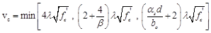
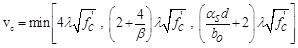 ACI 318-14 (Table 22.6.5.2)


 O.K.
O.K.
 For the interior
column:
For the interior
column:

For
the interior column in Figure 19, the location of the centroidal axis z-z is:

The polar moment Jc of the shear perimeter
is:

 ACI 318-14 (Eq. 8.4.4.2.2)
The length of the critical perimeter for the exterior
column:

 ACI 318-14 (Table 22.6.5.2)


 O.K.
O.K.
5. Two-Way
Slab Deflection Control (Serviceability Requirements)
Since the slab
thickness was selected based on the minimum slab thickness tables in ACI
318-14, the deflection calculations are not required. However, the calculations
of immediate and time-dependent deflections are covered in this section for
illustration and comparison with spSlab model results.
The calculation of
deflections for two-way slabs is challenging even if linear elastic behavior
can be assumed. Elastic analysis for three service load levels (D, D + Lsustained,
D+LFull) is used to obtain immediate deflections of the two-way
slab in this example. However, other procedures may be used if they result in
predictions of deflection in reasonable agreement with the results of
comprehensive tests. ACI
318-14 (24.2.3)
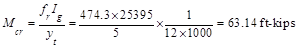
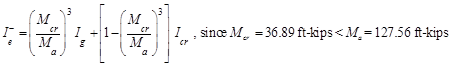
The
effective moment of inertia (Ie) is used to account for the
cracking effect on the flexural stiffness of the slab. Ie for
uncracked section (Mcr > Ma) is equal to Ig.
When the section is cracked (Mcr < Ma), then
the following equation should be used:
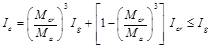 ACI 318-14 (Eq. 24.2.3.5a)
Where:
Ma = Maximum moment in member due to service loads at stage deflection is
calculated.
The
values of the maximum moments for the three service load levels are calculated
from structural analysis as shown previously in this document. These moments are
shown in Figure 20.
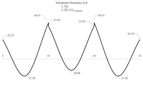
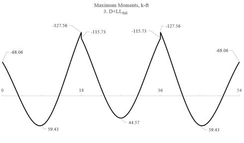
Figure 20 – Maximum Moments for the
Three Service Load Levels
For positive moment (midspan) section of the
exterior span:
 ACI
318-14 (Eq. 24.2.3.5b)
ACI
318-14 (Eq. 24.2.3.5b)

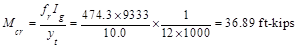
 ACI
318-14 (Eq. 19.2.3.1)
ACI
318-14 (Eq. 19.2.3.1)

yt = Distance from centroidal axis
of gross section, neglecting reinforcement, to tension face, in.
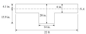
Figure 21 – Ig
calculations for slab section near support
 PCA Notes on ACI 318-11 (9.5.2.2)
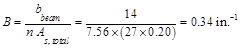
As
calculated previously, the positive reinforcement for the end span frame strip
is 22 #4 bars located at 1.0 in. along the slab section from the bottom of the
slab and 4 #4 bars located at 1.75 in. along the beam section from the bottom
of the beam. Five of the slab section bars are not continuous and will be
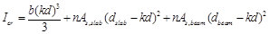
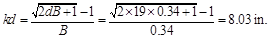
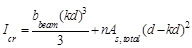
excluded from the calculation of Icr. Figure 22 shows all
the parameters needed to calculate the moment of inertia of the cracked section
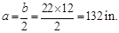
transformed to concrete at midspan.
Figure 22 – Cracked Transformed
Section (positive moment section)

 ACI
318-14 (19.2.2.1.a)
ACI
318-14 (19.2.2.1.a)
 PCA Notes on ACI 318-11 (Table 10-2)


For negative moment section (near the interior
support of the end span):
The
negative reinforcement for the end span frame strip near the interior support
is 27 #4 bars located at 1.0 in. along the section from the top of the slab.
 ACI
318-14 (Eq. 24.2.3.5b)
ACI
318-14 (Eq. 24.2.3.5b)
ACI
318-14 (Eq. 19.2.3.1)


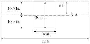
Figure 23 – Ig
calculations for slab section near support
ACI
318-14 (19.2.2.1.a)
PCA Notes on ACI 318-11 (Table 10-2)
 PCA
Notes on ACI 318-11 (Table 10-2)
PCA
Notes on ACI 318-11 (Table 10-2)
 PCA Notes
on ACI 318-11 (Table 10-2)
PCA Notes
on ACI 318-11 (Table 10-2)
 PCA
Notes on ACI 318-11 (Table 10-2)
PCA
Notes on ACI 318-11 (Table 10-2)
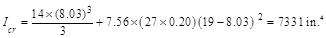
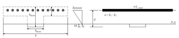
Figure 24
– Cracked Transformed Section (interior negative moment section for end span)
The effective moment of inertia procedure described in
the Code is considered sufficiently accurate to estimate deflections. The
effective moment of inertia, Ie, was developed to provide a
transition between the upper and lower bounds of Ig and Icr
as a function of the ratio Mcr/Ma. For conventionally
reinforced (nonprestressed) members, the effective moment of inertia, Ie,
shall be calculated by Eq. (24.2.3.5a) unless obtained by a more comprehensive
analysis.
Ie shall be
permitted to be taken as the value obtained from Eq. (24.2.3.5a) at midspan for
simple and continuous spans, and at the support for cantilevers.
ACI 318-14 (24.2.3.7)
For continuous one-way slabs
and beams. Ie shall be permitted to be taken as the average of
values obtained from Eq. (24.2.3.5a) for the critical positive and negative
moment sections. ACI 318-14 (24.2.3.6)
For the exterior span
(span with one end continuous) with service load level (D+LLfull):
ACI
318-14 (24.2.3.5a)
Where
Ie- is the effective moment of inertia for the
critical negative moment section (near the support).

Where
Ie+
is the effective moment of inertia for the critical positive moment section
(midspan).
Since
midspan stiffness (including the effect of cracking) has a dominant effect on
deflections, midspan section is heavily represented in calculation of Ie
and this is considered satisfactory in approximate deflection calculations. The averaged effective moment of inertia (Ie,avg)
is given by:
 PCA
Notes on ACI 318-11 (9.5.2.4(1))
PCA
Notes on ACI 318-11 (9.5.2.4(1))

Where:


For the interior span
(span with both ends continuous) with service load level (D+LLfull):

ACI
318-14 (24.2.3.5a)

The averaged effective
moment of inertia (Ie,avg) is given by:
 PCA Notes on ACI 318-11 (9.5.2.4(2))
Where:


Table 6
provides a summary of the required parameters and calculated values needed for
deflections for exterior and interior equivalent frame. It also provides a
summary of the same values for column strip and middle strip to facilitate
calculation of panel deflection.
|
Table 6 –
Averaged Effective Moment of Inertia Calculations
|
|
For Frame
Strip
|
|
Span
|
zone
|
Ig,
in.4
|
Icr,
in.4
|
Ma,
ft-kip
|
Mcr,
k-ft
|
Ie,
in.4
|
Ie,avg,
in.4
|
|
D
|
D +
LLSus
|
D +
Lfull
|
D
|
D +
LLSus
|
D +
Lfull
|
D
|
D +
LLSus
|
D +
Lfull
|
|
Ext
|
Left
|
9333
|
7147
|
-30.61
|
-30.61
|
-66.92
|
36.89
|
9333
|
9333
|
7513
|
22761
|
22761
|
22693
|
|
Midspan
|
25395
|
2282
|
27.19
|
27.19
|
59.43
|
63.14
|
25395
|
25395
|
25395
|
|
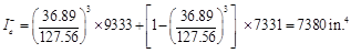
Right
|
9333
|
7331
|
-58.35
|
-58.35
|
-127.56
|
36.89
|
7837
|
7837
|
7380
|
|
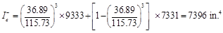
Int
|
Left
|
9333
|
7331
|
-52.93
|
-52.93
|
-115.73
|
36.89
|
8009
|
8009
|
7396
|
20179
|
20179
|
19995
|
|
Mid
|
25395
|
1553
|
18.06
|
18.06
|
44.57
|
63.14
|
25395
|
25395
|
25395
|
|
Right
|
9333
|
7331
|
-52.93
|
-52.93
|
-115.73
|
36.89
|
8009
|
8009
|
7396
|
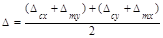
Deflections in two-way slab systems shall be
calculated taking into account size and shape of the panel, conditions of
support, and nature of restraints at the panel edges. For immediate deflections
two-way slab systems the midpanel
deflection is computed as the sum of deflection at midspan of the column strip
or column line in one direction (Δcx or Δcy)
and deflection at midspan of the middle strip in the orthogonal direction (Δmx
or Δmy). Figure 25 shows the deflection computation for
a rectangular panel. The average Δ for panels that have different
properties in the two direction is calculated as follows:
 PCA
Notes on ACI 318-11 (9.5.3.4 Eq. 8)
PCA
Notes on ACI 318-11 (9.5.3.4 Eq. 8)
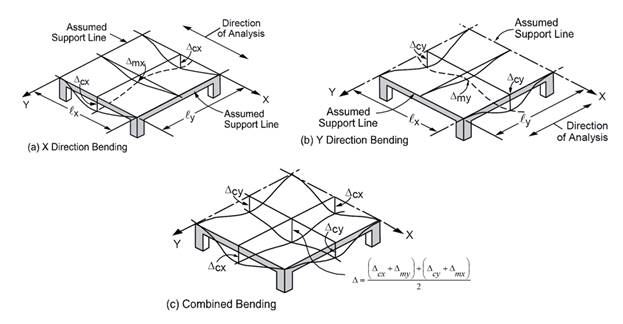
Figure 25 – Deflection Computation
for a rectangular Panel
To
calculate each term of the previous equation, the following procedure should be
used. Figure 26 shows the procedure of calculating the term Δcx.
same procedure can be used to find the other terms.
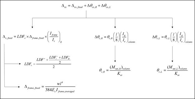
Figure 26 –Δcx calculation
procedure
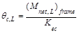
For exterior span - service
dead load case:
 PCA
Notes on ACI 318-11 (9.5.3.4 Eq. 10)
PCA
Notes on ACI 318-11 (9.5.3.4 Eq. 10)
Where:


 ACI
318-14 (19.2.2.1.a)
ACI
318-14 (19.2.2.1.a)
Iframe,averaged =
The averaged effective moment of inertia (Ie,avg)
for the frame strip for service dead load case from Table 6 = 22761 in.4

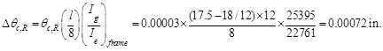
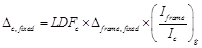 PCA
Notes on ACI 318-11 (9.5.3.4 Eq. 11)
PCA
Notes on ACI 318-11 (9.5.3.4 Eq. 11)
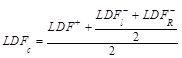
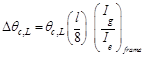
Where LDFc
is the load distribution factor for the column strip. The load distribution
factor for the column strip can be found from the following equation:
And the load distribution
factor for the middle strip can be found from the following equation:

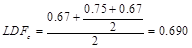
For the
end span, LDF for exterior negative region (LDFL¯), interior
negative region (LDFR¯), and positive region (LDFL+) are 0.75, 0.67, and 0.67, respectively (From Table 2 of this document).
Thus, the load distribution factor for the column strip for the end span is
given by:
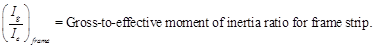
Ic,g
= The gross moment of inertia (Ig)
for the column strip (for T section) = 20040 in.4
Iframe,g
= The gross moment of inertia (Ig)
for the frame strip (for T section) = 25395 in.4

 PCA
Notes on ACI 318-11 (9.5.3.4 Eq. 12)
PCA
Notes on ACI 318-11 (9.5.3.4 Eq. 12)
Where:


Kec = effective column stiffness
for exterior column.
= 764 x
Ec = 2929 x 106 in.-lb
(calculated previously).
 PCA
Notes on ACI 318-11 (9.5.3.4 Eq. 14)
PCA
Notes on ACI 318-11 (9.5.3.4 Eq. 14)
Where:

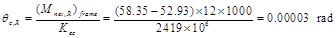
Where


Kec = effective column stiffness
for interior column.
= 631 x
Ec = 2419 x 106 in.-lb
(calculated previously).
Where:

 PCA
Notes on ACI 318-11 (9.5.3.4 Eq. 9)
PCA
Notes on ACI 318-11 (9.5.3.4 Eq. 9)

Following
the same procedure, Δmx can be calculated for the middle
strip. This procedure is repeated for the equivalent frame in the orthogonal
direction to obtain Δcy, and Δmy
for the end and middle spans for the other load levels (D+LLsus
and D+LLfull).
Assuming
square panel, Δcx = Δcy= 0.009
in. and Δmx = Δmy=
0.021 in.
The
average Δ for the corner panel is calculated as follows: