Code
Building
Code Requirements for Structural Concrete (ACI 318-14) and Commentary (ACI
318R-14)
Reference
Concrete
Floor Systems (Guide to Estimating and Economizing), Second Edition, 2002 David
A. Fanella, Portland Cement Association.
PCA
Notes on ACI 318-11 Building Code Requirements for Structural Concrete, Twelfth
Edition, 2013, Portland Cement Association.
Simplified
Design of Reinforced Concrete Buildings, Fourth Edition, 2011 Mahmoud E. Kamara
and Lawrence C. Novak
Control
of Deflection in Concrete Structures (ACI 435R-95), American Concrete Institute
Reinforced
Concrete Design .. .Hassoun, McGraw Hill
Design Data
Story Height = 13 ft
(provided by architectural drawings)
Superimposed Dead Load,
SDL = 50 psf for Frame walls, hollow concrete masonry unit wythe, 12 in.
thick, 125 pcf unit density, with no grout
ASCE/SEI
7-10 (Table C3-1)
Live Load, LL =
100 psf for Recreational uses – Gymnasiums ASCE/SEI
7-10 (Table 4-1)
fc’ = 5000 psi (for slab)
fc’ = 6000 psi (for columns)
fy = 60,000 psi
Solution
Preliminary Flat Plate (without Joists)
a.
Slab minimum
thickness – Deflection ACI
318-14 (8.3.1.1)
In lieu of
detailed calculation for deflections, ACI 318 minimum slab thickness for
two-way construction without interior beams is given in Table 8.3.1.1.
For flat plate slab system,
the minimum slab thickness per ACI 318-14 are:
 ACI 318-14 (Table 8.3.1.1)
But not less than 5 in. ACI
318-14 (8.3.1.1(a))
 ACI 318-14 (Table 8.3.1.1)
But not less than 5 in. ACI
318-14 (8.3.1.1(a))
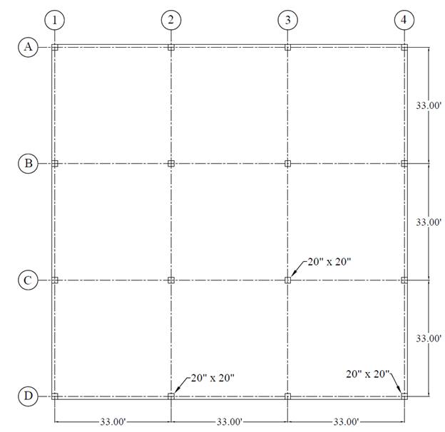
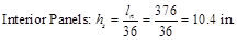
Where ln
= length of clear span in the long direction = 33 x 12 – 20 = 376 in.
Use 13 in. slab for all
panels (self-weight = 150 pcf x 13 in. /12 = 162.5 psf)
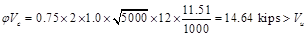
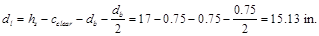
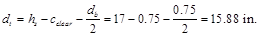
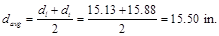
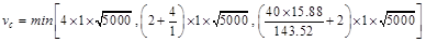
b. Slab shear strength – one way shear
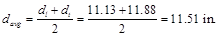
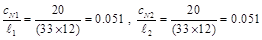
Evaluate the average
effective depth (Figure 2):
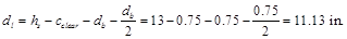
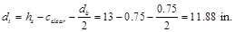
Where:
cclear = 3/4 in. for
# 6 steel bar ACI
318-14 (Table 20.6.1.3.1)
db = 0.75 in. for # 6 steel bar
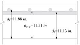
Figure 2 - Two-Way Flat Concrete Floor System

 ACI
318-14 (5.3.1)
ACI
318-14 (5.3.1)

Check the adequacy of
slab thickness for beam action (one-way shear) ACI
318-14 (22.5)
at an interior column:
Consider a 12-in. wide
strip. The critical section for one-way shear is located at a distance d,
from the face of support (see Figure 3):


 ACI
318-14 (Eq. 22.5.5.1)
ACI
318-14 (Eq. 22.5.5.1)

Slab thickness of 13 in.
is adequate for one-way shear.
c.
Slab shear
strength – two-way shear
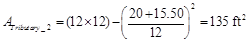
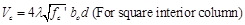
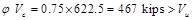
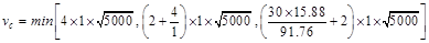
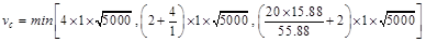
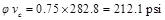
Check the adequacy of
slab thickness for punching shear (two-way shear) at an interior column (Figure
4):


 ACI
318-14 (Table 22.6.5.2(a))
ACI
318-14 (Table 22.6.5.2(a))

Slab thickness of 13 in. is not adequate
for two-way shear. This is expected as the self-weight an applied loads are very
challenging for a flat plate system.
Figure 3 –
Critical Section for One-Way Shear Figure 4 – Critical Section for Two-Way Shear
In
this case, four options can be considered: 1) increase the slab thickness
further, 2) use headed shear reinforcement in the slab, 3) apply drop panels at
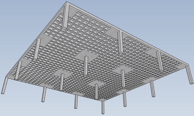
columns, or 4) use two-way joist slab system. In this example, the latter
option will be used to achieve better understanding for the design of two-way joist
slab often called two-way ribbed slab or waffle slab.
Check the applicable joist
dimensional limitations as follows:
1)
Width of ribs
shall be at least 4 in. at any location along the depth. ACI
318-14 (9.8.1.2)
Use ribs with 6 in. width.
2)
Overall depth of
ribs shall not exceed 3.5 times the minimum width. ACI
318-14 (9.8.1.3)
3.5 x 6 in. = 21 in. à Use ribs with 14 in. depth.
3)
Clear spacing
between ribs shall not exceed 30 in. ACI
318-14 (9.8.1.4)
Use 30 in. clear spacing.
4)
Slab thickness (with
removable forms) shall be at least the greater of: ACI
318-14 (8.8.3.1)
a)
1/12 clear
distance between ribs = 1/12 x 30 = 2.5 in.
b)
2 in.
Use a slab thickness of 3
in. > 2.5 in.
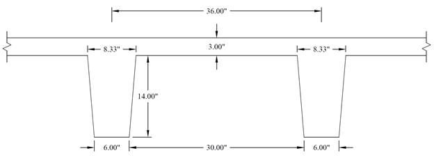
Figure 5 – Joists Dimensions
In waffle slabs a drop panel is
automatically invoked to guarantee adequate two-way (punching) shear resistance
at column supports. This is evident from the flat plate check conducted using
13 in. indicating insufficient punching shear capacity above. Check the drop panel dimensional limitations as
follows:
1)
The drop panel
shall project below the slab at least one-fourth of the adjacent slab
thickness.
ACI
318-14 (8.2.4(a))
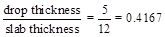
Since the slab thickness (hMI – calculated in page 7 of this
document) is 12 in., the thickness of the drop panel should be at least:

Drop panel depth are also controlled
by the rib depth (both at the same level).For nominal lumber size (2x), hdp
= hrib = 14 in. > hdp, min = 3
in.
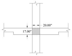
The total thickness including the actual
slab and the drop panel thickness (h) = hs + hdp
= 3 + 14 = 17 in.
2)
The drop panel
shall extend in each direction from the centerline of support a distance not
less than one-sixth the span length measured from center-to-center of supports
in that direction.
ACI
318-14 (8.2.4(b))
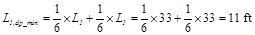

Based on the previous
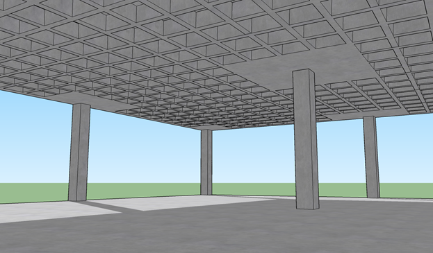
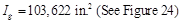
discussion, Figure 6 shows the dimensions of the selected two-way joist system.
Figure 6 – Two-Way Joist (Waffle) Slab
Preliminary Two-Way Joist Slab (Waffle Slab)
For slabs with changes in thickness and subjected to
bending in two directions, it is necessary to check shear at multiple sections
as defined in the ACI 318-14. The critical sections shall
be located with respect to:
1) Edges or corners of
columns. ACI 318-14 (22.6.4.1(a))
2) Changes in slab
thickness, such as edges of drop panels. ACI 318-14 (22.6.4.1(b))
a.
Slab minimum
thickness – Deflection ACI
318-14 (8.3.1.1)
In lieu of
detailed calculation for deflections, ACI 318 Code gives minimum slab thickness
for two-way construction without interior beams in Table 8.3.1.1.
For this slab system, the
minimum slab thicknesses per ACI 318-14 are:
 ACI 318-14 (Table 8.3.1.1)
But not less than 4 in. ACI
318-14 (8.3.1.1(b))
 ACI 318-14 (Table 8.3.1.1)
But not less than 4 in. ACI
318-14 (8.3.1.1(b))
Where ln
= length of clear span in the long direction = 33 x 12 – 20 = 376 in.
For the purposes of
analysis and design, the ribbed slab will be replaced with a solid slab of
equivalent moment of inertia, weight, punching shear capacity, and one-way
shear capacity.
The
equivalent thickness based on moment of inertia is used to find slab stiffness
considering the ribs in the direction of the analysis only. The ribs spanning
in the transverse direction are not considered in the stiffness computations.
This thickness, hMI, is given by:
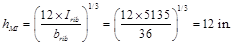 spSlab Software Manual (Eq. 2-11)
Where:
Irib = Moment of inertia of one joist
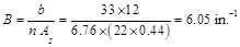
section between centerlines of ribs (see Figure 7a).
brib = The center-to-center distance
of two ribs (clear rib spacing plus rib width) (see Figure 7a).
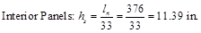
Since hMI
= 12 in. > hmin = 11.4 in., the deflection calculation can
be neglected. However, the deflection calculation will be included in this
example for comparison with the spSlab software results.
The drop
panel depth for two-way joist (waffle) slab is set equal to the rib depth. The
equivalent drop depth based on moment of inertia, dMI, is
given by:
 spSlab Software Manual (Eq. 2-12)
Where hrib
= 3 + 14 – 12 = 5 in.
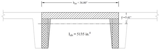
Figure 7a – Equivalent Thickness Based on Moment of Inertia
Find system self-weight
using the equivalent thickness based on the weight of individual components
(see the following Figure). This thickness, hw, is given by:
 spSlab Software Manual (Eq. 2-10)
Where:
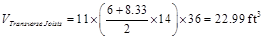
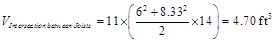
Vmod = The Volume of one joist module
(the transverse joists are included – 11 joists in the frame strip).

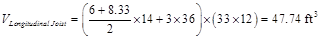
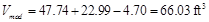
Amod = The plan area of one joist module
= 33 x 36/12 = 99 ft2
Self-weight for slab
section without drop panel = 150 pcf x 8 in. /12 = 100.057 psf
Self-weight for drop panel = 150 pcf x
(14 + 3 – 8) in. /12 = 112.44 psf
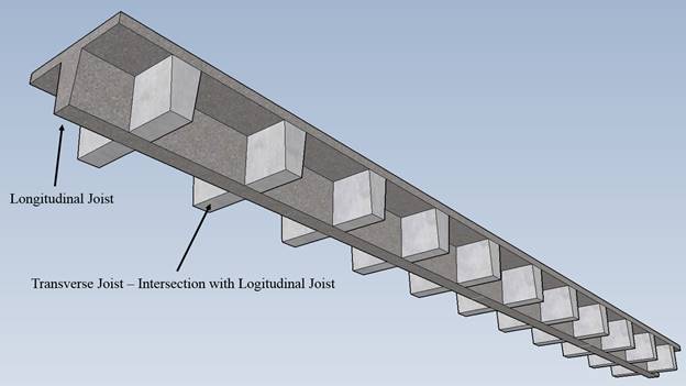
Figure 7b
– Equivalent Thickness Based on the Weight of Individual Components
b. Slab shear strength – one-way shear
For critical section
at distance d from the edge of the column (slab section with drop
panel):
Evaluate the average
effective depth:
Where:
cclear = 3/4 in. for # 6 steel bar ACI
318-14 (Table 20.6.1.3.1)
db = 0.75 in. for # 6 steel bar
hs = 17 in. = The drop depth (dMI)

 ACI
318-14 (5.3.1)
ACI
318-14 (5.3.1)

Check the adequacy of
slab thickness for beam action (one-way shear) from the edge of the interior
column
ACI 318-14 (22.5)
Consider a 12-in. wide
strip. The critical section for one-way shear is located at a distance d,
from the edge of the column (see Figure 8)


 ACI
318-14 (Eq. 22.5.5.1)
ACI
318-14 (Eq. 22.5.5.1)

Slab thickness is
adequate for one-way shear for the first critical section (from the edge of the
column).
For critical section
at the edge of the drop panel (slab section without drop panel):
Evaluate the average
effective depth:
Where:
cclear = 3/4 in. for
# 6 steel bar ACI
318-14 (Table 20.6.1.3.1)
db = 0.75 in. for # 6 steel bar

ACI
318-14 (5.3.1)

Check the
adequacy of slab thickness for beam action (one-way shear) from the edge of the
interior drop panel ACI 318-14 (22.5)
Consider a 12-in. wide
strip. The critical section for one-way shear is located at the face of the solid
head (see Figure 8)

ACI
318-14 (Eq. 22.5.5.1)
Slab thickness of 12 in.
is adequate for one-way shear for the second critical section (at the edge of
the drop panel).
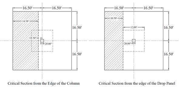
Figure 8 – Critical Sections for One-Way Shear
c.
Slab shear
strength – two-way shear
For critical section at distance d/2 from the edge of the column
(slab section with drop panel):
Check the adequacy of slab thickness
for punching shear (two-way shear) at an interior column (Figure 9):
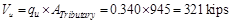
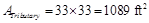
Tributary area of two-way
shear for the slab without the drop panel is:
Tributary area of two-way
shear for the slab with the drop panel is:

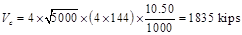
 ACI
318-14 (Table 22.6.5.2(a))
ACI
318-14 (Table 22.6.5.2(a)) 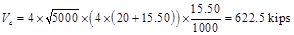
Slab thickness is adequate for
two-way shear for the first critical section (from the edge of the column).
For critical section at the edge of the drop panel
(slab section without drop panel):
Check the adequacy of slab thickness
for punching shear (two-way shear) at an interior drop panel (Figure 9):

ACI
318-14 (Table 22.6.5.2(a))

Slab thickness of 12 in. is adequate
for two-way shear for the second critical section (from the edge of the drop
panel).
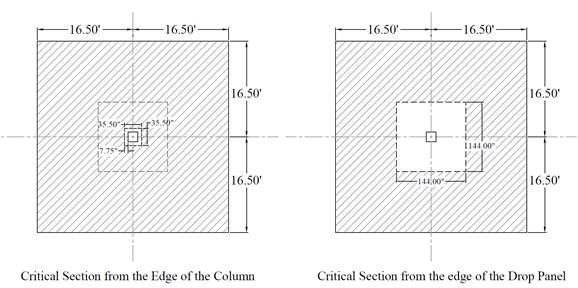
Figure 9 – Critical Sections for Two-Way Shear
d. Column dimensions - axial load
Check the adequacy of
column dimensions for axial load:
Tributary area for
interior column for live load, superimposed dead load, and self-weight of the
slab is
Tributary area for
interior column for self-weight of additional slab thickness due to the
presence of the drop panel is

Assuming four story
building

Assume 20 in. square
column with 12 – No. 11 vertical bars with design axial strength, φPn,max
of
 ACI
318-14 (22.4.2)
ACI
318-14 (22.4.2)


Column dimensions of 20 in. x 20
in. are adequate for axial load.
ACI 318 states that a slab system shall be designed by
any procedure satisfying equilibrium and geometric compatibility, provided that
strength and serviceability criteria are satisfied. Distinction of two-systems
from one-way systems is given by ACI 318-14 (R8.10.2.3 & R8.3.1.2).
ACI 318 permits the use of Direct
Design Method (DDM) and Equivalent Frame Method (EFM) for the gravity load
analysis of orthogonal frames and is applicable to flat plates, flat slabs, and
slabs with beams. The following sections outline the solution per EFM and
spSlab software. For the solution per DDM, check the flat plate example.
EFM is the most comprehensive and
detailed procedure provided by the ACI 318 for the analysis and design of
two-way slab systems where the structure is modeled by a series of equivalent
frames (interior and exterior) on column lines taken longitudinally and
transversely through the building.
The equivalent frame consists of three
parts (for a detailed discussion of this method, refer to the
flat plate design example):
1) Horizontal slab-beam strip.
2) Columns or other vertical supporting
members.
3) Elements of the structure (Torsional
members) that provide moment transfer between the horizontal and vertical
members.
In EFM, live load shall be arranged in accordance with
6.4.3 which requires slab systems to be analyzed and designed for the most
demanding set of forces established by investigating the effects of live load
placed in various critical patterns. ACI 318-14 (8.11.1.2 & 6.4.3)
Complete analysis must include representative interior
and exterior equivalent frames in both the longitudinal and transverse
directions of the floor. ACI 318-14 (8.11.2.1)
Panels
shall be rectangular, with a ratio of longer to shorter panel dimensions,
measured center-to-center of supports, not to exceed 2. ACI 318-14 (8.10.2.3)
Determine moment distribution factors and fixed-end
moments for the equivalent frame members. The moment distribution procedure
will be used to analyze the equivalent frame. Stiffness factors k, carry over factors COF, and fixed-end moment factors
FEM for the slab-beams and column members are determined using the design aids tables
at Appendix 20A of PCA Notes on ACI 318-11. These
calculations are shown below.
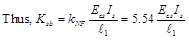
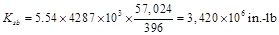
a. Flexural stiffness of slab-beams at
both ends, Ksb.

 PCA Notes
on ACI 318-11 (Table A1)
PCA Notes
on ACI 318-11 (Table A1)
 PCA
Notes on ACI 318-11 (Table A1)
PCA
Notes on ACI 318-11 (Table A1)

 ACI 318-14 (19.2.2.1.a)
Carry-over factor COF = 0.54 PCA
Notes on ACI 318-11 (Table A1)
 PCA
Notes on ACI 318-11 (Table A1)
PCA
Notes on ACI 318-11 (Table A1)
Uniform load fixed end moment coefficient, mNF1
= 0.0911
Fixed end moment coefficient for (b-a) = 0.2 when a =
0, mNF2 = 0.0171
Fixed end moment coefficient for (b-a) = 0.2 when a = 0.8, mNF3
= 0.0016
b.
Flexural
stiffness of column members at both ends, Kc.
Referring to Table A7, Appendix 20A,
For the Bottom Column:


 PCA
Notes on ACI 318-11 (Table A7)
PCA
Notes on ACI 318-11 (Table A7)


 ACI 318-14 (19.2.2.1.a)
lc = 13 ft = 156 in.
For the Top Column:


 PCA
Notes on ACI 318-11 (Table A7)
PCA
Notes on ACI 318-11 (Table A7)
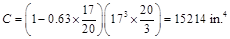
c. Torsional stiffness of torsional
members,  .
.
 ACI 318-14 (R.8.11.5)
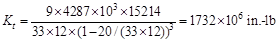
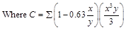 ACI 318-14 (Eq. 8.10.5.2b)
d. Equivalent column stiffness Kec.
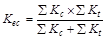
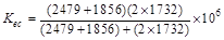

Where∑
Kt is for two torsional
members one on each side of the column, and ∑ Kc is for
the upper and lower columns at the slab-beam joint of an intermediate floor.
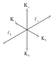
Figure
10 – Torsional Member Figure 11 – Column and Edge of Slab
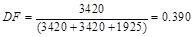
e.
Slab-beam joint
distribution factors, DF.
At exterior joint,
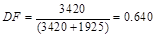
At interior joint,
COF for slab-beam =0.576
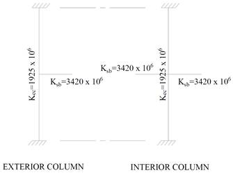
Figure 12 – Slab and Column Stiffness
Determine negative and positive moments for the
slab-beams using the moment distribution method. Since the unfactored live load
does not exceed three-quarters of the unfactored dead load, design moments are
assumed to occur at all critical sections with full factored live on all spans. ACI
318-14 (6.4.3.2)
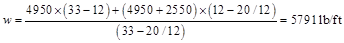
a. Factored load and Fixed-End Moments
(FEM’s).
For slab:


For drop panels:


PCA
Notes on ACI 318-11 (Table A1)


b. Moment distribution. Computations are
shown in Table 1. Counterclockwise rotational moments acting on the member ends
are taken as positive. Positive span moments are determined from the following
equation:
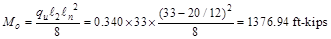
Where Mo is the
moment at the midspan for a simple beam.
When the end moments are not equal, the maximum moment
in the span does not occur at the midspan, but its value is close to that
midspan for this example.
Positive moment in span 1-2:


|
Table 1 - Moment Distribution for Equivalent Frame
|
|
|
|
Joint
|
1
|
2
|
3
|
4
|
|
Member
|
1-2
|
2-1
|
2-3
|
3-2
|
3-4
|
4-3
|
|
DF
|
0.640
|
0.390
|
0.390
|
0.390
|
0.390
|
0.640
|
|
COF
|
0.576
|
0.576
|
0.576
|
0.576
|
0.576
|
0.576
|
|
FEM
|
1146.51
|
-1146.5
|
1146.51
|
-1146.5
|
1146.51
|
-1146.5
|
|
Dist
|
-733.6
|
0.0
|
0.0
|
0.0
|
0.0
|
733.6
|
|
CO
|
0.0
|
-422.5
|
0.0
|
0.0
|
422.5
|
0.0
|
|
Dist
|
0.0
|
164.8
|
164.8
|
-164.8
|
-164.8
|
0.0
|
|
CO
|
94.9
|
0.0
|
-94.9
|
94.9
|
0.0
|
-94.9
|
|
Dist
|
-60.7
|
37.0
|
37.0
|
-37.0
|
-37.0
|
60.7
|
|
CO
|
21.3
|
-35.0
|
-21.3
|
21.3
|
35.0
|
-21.3
|
|
Dist
|
-13.7
|
22.0
|
22.0
|
-22.0
|
-22.0
|
13.7
|
|
CO
|
12.7
|
-7.9
|
-12.7
|
12.7
|
7.9
|
-12.7
|
|
Dist
|
-8.1
|
8.0
|
8.0
|
-8.0
|
-8.0
|
8.1
|
|
CO
|
4.6
|
-4.7
|
-4.6
|
4.6
|
4.7
|
-4.6
|
|
Dist
|
-3.0
|
3.6
|
3.6
|
-3.6
|
-3.6
|
3.0
|
|
CO
|
2.1
|
-1.7
|
-2.1
|
2.1
|
1.7
|
-2.1
|
|
Dist
|
-1.3
|
1.5
|
1.5
|
-1.5
|
-1.5
|
1.3
|
|
CO
|
0.9
|
-0.8
|
-0.9
|
0.9
|
0.8
|
-0.9
|
|
Dist
|
-0.6
|
0.6
|
0.6
|
-0.6
|
-0.6
|
0.6
|
|
CO
|
0.4
|
-0.3
|
-0.4
|
0.4
|
0.3
|
-0.4
|
|
Dist
|
-0.2
|
0.3
|
0.3
|
-0.3
|
-0.3
|
0.2
|
|
CO
|
0.2
|
-0.1
|
-0.2
|
0.2
|
0.1
|
-0.2
|
|
Dist
|
-0.1
|
0.1
|
0.1
|
-0.1
|
-0.1
|
0.1
|
|
CO
|
0.1
|
-0.1
|
-0.1
|
0.1
|
0.1
|
-0.1
|
|
Dist
|
0.0
|
0.1
|
0.1
|
-0.1
|
-0.1
|
0.0
|
|
CO
|
0.0
|
0.0
|
0.0
|
0.0
|
0.0
|
0.0
|
|
Dist
|
0.0
|
0.0
|
0.0
|
0.0
|
0.0
|
0.0
|
|
M, k-ft
|
462.3
|
-1381.5
|
1247.5
|
-1247.5
|
1381.5
|
-462.3
|
|
Midspan M,
ft-kips
|
630.0
|
304.4
|
630.0
|
Positive and
negative factored moments for the slab system in the direction of analysis are
plotted in Figure 13. The negative moments used for design are taken at the
faces of supports (rectangle section or equivalent rectangle for circular or
polygon sections) but not at distances greater than 0.175 l1
from the centers of supports. ACI
318-14 (8.11.6.1)

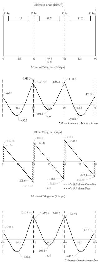
Figure 13 -
Positive and Negative Design Moments for Slab-Beam (All Spans Loaded with Full
Factored Live Load)
a. Check whether the moments calculated above can take
advantage of the reduction permitted by ACI 318-14 (8.11.6.5):
If the slab
system analyzed using EFM within the limitations of ACI 318-14
(8.10.2), it is permitted by the ACI code to reduce the calculated
moments obtained from EFM in such proportion that the absolute sum of the
positive and average negative design moments need not exceed the total static
moment Mo given by Equation 8.10.3.2 in
the ACI 318-14.
Check Applicability
of Direct Design Method:
1.
There is a
minimum of three continuous spans in each direction. ACI
318-14 (8.10.2.1)
2.
Successive span
lengths are equal. ACI
318-14 (8.10.2.2)
3.
Long-to-Short
ratio is 33/33 = 1.0 < 2.0. ACI
318-14 (8.10.2.3)
4.
Columns are not
offset. ACI
318-14 (8.10.2.4)
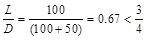
5.
Loads are gravity
and uniformly distributed with service live-to-dead ratio of 0.67 < 2.0
(Note: The self-weight of the drop
panels is not uniformly distributed entirely along the span. However, the
variation in load magnitude is small).
ACI
318-14 (8.10.2.5 and 6)
6.
Check relative
stiffness for slab panel. ACI
318-14 (8.10.2.7)
Slab
system is without beams and this requirement is not applicable.
 ACI 318-14 (Eq. 8.10.3.2)
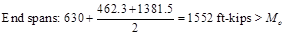

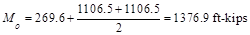
To illustrate proper procedure, the interior span
factored moments may be reduced as follows:
Permissible reduction = 1376.9/1552 = 0.887
Adjusted negative
design moment = 1247.5 × 0.887 = 1106.5 ft-kips
Adjusted positive
design moment = 304 × 0.887 = 269.6 ft-kips
ACI 318 allows the reduction of the moment values
based on the previous procedure. Since the drop panels may cause gravity loads
not to be uniform (Check limitation #5 and Figure 13), the moment values
obtained from EFM will be used for comparison reasons.
b. Distribute factored moments to column and middle
strips:
After the negative and positive moments have been
determined for the slab-beam strip, the ACI code permits the distribution of
the moments at critical sections to the column strips, beams (if any), and
middle strips in accordance with the DDM. ACI
318-14 (8.11.6.6)
Distribution of factored moments at critical sections
is summarized in Table 2.
|
Table 2 - Distribution of factored
moments
|
|
|
Slab-beam Strip
|
Column Strip
|
Middle Strip
|
|
Moment
(ft-kips)
|
Percent
|
Moment
(ft-kips)
|
Percent
|
Moment
(ft-kips)
|
|
End Span
|
Exterior Negative
|
335.1
|
100
|
335.1
|
0
|
0.0
|
|
Positive
|
630.0
|
60
|
378.0
|
40
|
252.0
|
|
Interior Negative
|
1207.9
|
75
|
905.9
|
25
|
302.0
|
|
Interior Span
|
Negative
|
1097.1
|
75
|
822.8
|
25
|
274.3
|
|
Positive
|
304.4
|
60
|
182.6
|
40
|
121.8
|
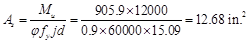
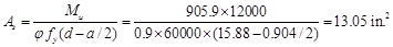
a. Determine flexural reinforcement required for strip
moments
The flexural reinforcement calculation for the column
strip of end span – interior negative location:

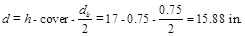
Use d = 15.88 in. (slab with drop panel where h
= 17 in.)
To determine the area of steel, assumptions have to be
made whether the section is tension or compression controlled, and regarding
the distance between the resultant compression and tension forces along the
slab section (jd). In this example, tension-controlled section will be
assumed so the reduction factor is equal to 0.9, and jd will be taken equal to 0.95d.
The assumptions will be verified once the area of steel in finalized.
is equal to 0.9, and jd will be taken equal to 0.95d.
The assumptions will be verified once the area of steel in finalized.


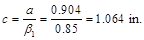
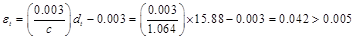
Therefore, the assumption that section is
tension-controlled is valid.
Two values of thickness must be considered. The slab
thickness in the column strip is 17 in. with the drop panel and 8 in. for the equivalent
slab without the drop panel based on the system weight.

 ACI 318-14 (24.4.3.2)

 ACI 318-14 (24.4.3.3)
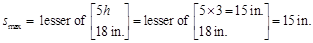
Provide 30 - #6 bars with As = 13.20
in.2 and s = 198/30 = 6.6 in. ≤ smax
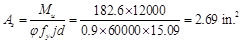
The flexural reinforcement calculation for the column
strip of interior span – positive location:

Use d = 15.88 in. (slab with rib where h
= 17 in.)
To determine the area of steel, assumptions have to be
made whether the section is tension or compression controlled, and regarding
the distance between the resultant compression and tension forces along the slab
section (jd). In this example, tension-controlled section will be
assumed so the reduction factoris equal to 0.9, and jd will be taken equal to 0.95d.
The assumptions will be verified once the area of steel in finalized.

Therefore, the assumption that section is
tension-controlled is valid.
 ACI 318-14 (24.4.3.2)


Since column strip has
5 ribs à provide 10 - #6 bars (2
bars/ rib):

Based on the procedures outlined above, values for all
span locations are given in Table 3.
|
Table 3 - Required Slab Reinforcement for
Flexure [Equivalent Frame Method (EFM)]
|
|
Span Location
|
Mu
(ft-kips)
|
b
(in.)
|
d (in.)
|
As Req’d for flexure (in.2)
|
Min As (in.2)
|
Reinforcement Provided
|
As Prov. for flexure (in.2)
|
|
End Span
|
|
Column Strip
|
Exterior Negative
|
335.1
|
198
|
15.88
|
4.74
|
5.18
|
14-#6 * **
|
6.16
|
|
Positive (5 ribs)
|
378.0
|
198
|
15.81
|
5.38
|
2.85
|
10-#7
(2 bars / rib)
|
6.00
|
|
Interior Negative
|
905.9
|
198
|
15.88
|
13.05
|
5.18
|
30-#6
|
13.20
|
|
Middle Strip
|
Exterior Negative
|
0.0
|
198
|
15.88
|
0.0
|
5.18
|
14-#6 * **
|
6.16
|
|
Positive (6 ribs)
|
252.0
|
198
|
15.88
|
3.56
|
2.85
|
12-#6
(2 bars / rib)
|
5.28
|
|
Interior Negative
|
302.0
|
198
|
15.88
|
4.27
|
5.18
|
14-#6 * **
|
6.16
|
|
Interior Span
|
|
Column Strip
|
Positive (5 ribs)
|
182.6
|
198
|
15.88
|
2.57
|
2.85
|
10-#6 *
(2 bars / rib)
|
4.40
|
|
Middle Strip
|
Positive (6 ribs)
|
121.8
|
198
|
15.88
|
1.71
|
2.85
|
12-#6 *
(2 bars / rib)
|
5.28
|
|
* Design governed by minimum reinforcement.
** Number of bars governed by maximum allowable spacing.
|
b. Calculate additional slab reinforcement at columns
for moment transfer between slab and column by flexure
The factored slab moment resisted by the column (γf
Msc) shall be assumed to be transferred by flexure.
Concentration of reinforcement over the column by closer spacing or additional
reinforcement shall be used to resist this moment. The fraction of slab moment
not calculated to be resisted by flexure shall be assumed to be resisted by
eccentricity of shear. ACI 318-14 (8.4.2.3)
Portion of the unbalanced moment transferred by
flexure is γf Msc ACI
318-14 (8.4.2.3.1)
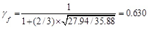
Where
 ACI
318-14 (8.4.2.3.2)
ACI
318-14 (8.4.2.3.2)
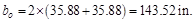
b1
= Dimension of the critical section bo
measured in the direction of the span for which
moments are determined in ACI 318, Chapter 8 (see Figure 14).
b2
= Dimension of the critical section  measured in the direction perpendicular to
  in ACI 318, Chapter 8 (see Figure 14).
 ACI
318-14 (8.4.2.3.3)
ACI
318-14 (8.4.2.3.3)
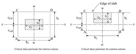
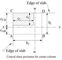
Figure 14 – Critical
Shear Perimeters for Columns
For exterior support:


Using the same procedure in 2.1.6.a, the required area
of steel:

However, the area of steel provided to resist the
flexural moment within the effective slab width bb:

Then, the required additional reinforcement at
exterior column for moment transfer between slab and column:

Provide 5 - #6 additional bars with As
= 2.20 in.2
Based on the procedure outlined above, values for all
supports are given in Table 4.
|
Table 4 - Additional Slab Reinforcement
required for moment transfer between slab and column (EFM)
|
|
Span Location
|
Msc*
(ft-kips)
|
γf
|
γf Msc
(ft-kips)
|
Effective slab
width, bb
(in.)
|
d
(in.)
|
As req’d
within bb
(in.2)
|
As prov. For
flexure within bb
(in.2)
|
Add’l
Reinf.
|
|
End Span
|
|
Column Strip
|
Exterior Negative
|
462.3
|
0.630
|
291
|
71
|
15.88
|
4.184
|
2.209
|
5-#6
|
|
Interior Negative
|
133.4
|
0.600
|
80.4
|
71
|
15.88
|
2.029
|
4.733
|
-
|
|
*Msc is taken at the
centerline of the support in Equivalent Frame Method solution.
|
The unbalanced moment from the slab-beams at the
supports of the equivalent frame are distributed to the support columns above
and below the slab-beam in proportion to the relative stiffness of the support
columns. Referring to Figure 13, the unbalanced moment at the exterior and
interior joints are:
Exterior Joint = +462.3 ft-kips
Joint 2= -1381.5 + 1247.5 = -134 ft-kips
The stiffness and carry-over factors of the actual
columns and the distribution of the unbalanced slab moments (Msc)
to the exterior and interior columns are shown in Figure 14.
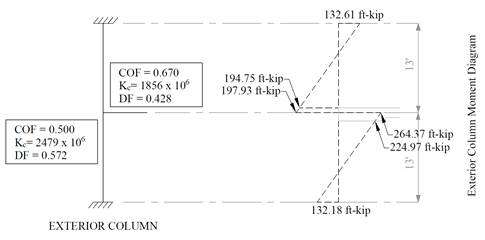
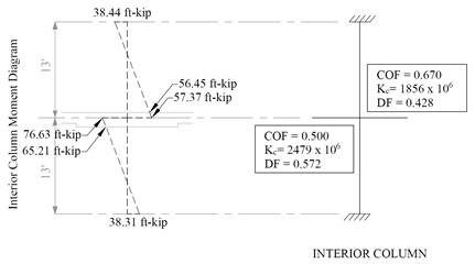
Figure 15 -
Column Moments (Unbalanced Moments from Slab-Beam)
In summary:
For Top column: For
Bottom column:
Mcol,Exterior= 194.75 ft-kips Mcol,Exterior=
224.97 ft-kips
Mcol,Interior = 56.45
ft-kips Mcol,Interior = 65.21
ft-kips
The moments determined above are combined with the
factored axial loads (for each story) and factored moments in the transverse
direction for design of column sections. The moment values at the face of
interior, exterior, and corner columns from the unbalanced moment values are
shown in the following table.
|
Table 5 – Factored Moments in Columns
|
|
Mu
kips-ft
|
Column Location
|
|
Interior
|
Exterior
|
Corner
|
|
Mux
|
65.21
|
224.97
|
224.97
|
|
Muy
|
65.21
|
65.21
|
224.97
|
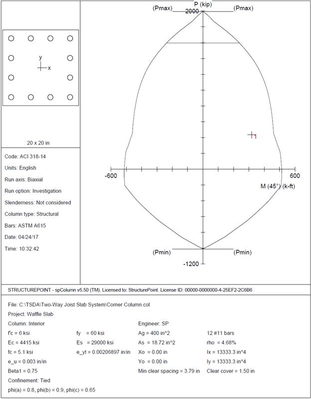
This section includes the design of
interior, edge, and corner columns using spColumn
software. The preliminary dimensions for these columns were calculated
previously in section one. The reduction of live load per ASCE 7-10
will be ignored in this example. However, the detailed procedure to calculate
the reduced live loads is explained in the “wide-Module
Joist System” example.
Interior Column:
Assume 4 story building
Tributary
area for interior column for live load, superimposed dead load, and self-weight
of the slab is

Tributary
area for interior column for self-weight of additional slab thickness due to
the presence of the drop panel is
Assuming five story
building

Mu,x = 65.21 ft-kips (see the previous Table)
Mu,y = 65.21 ft-kips (see the
previous Table)
Edge (Exterior) Column:
Tributary area for exterior
column for live load, superimposed dead load, and self-weight of the slab is
Tributary area for exterior
column for self-weight of additional slab thickness due to the presence of the
drop panel is

Mu,x = 224.97 ft-kips (see the previous Table)
Mu,y = 65.21 ft-kips (see the
previous Table)
Corner Column:
Tributary area for corner
column for live load, superimposed dead load, and self-weight of the slab is

Tributary area for corner
column for self-weight of additional slab thickness due to the presence of the
drop panel is


Mu,x = 224.97 ft-kips (see the previous Table)
Mu,y = 224.97 ft-kips (see the
previous Table)
Interior Column:
Edge Column:
Corner Column:
Shear strength of the slab in the vicinity
of columns/supports includes an evaluation of one-way shear (beam action) and
two-way shear (punching) in accordance with ACI 318 Chapter 22.
ACI
318-14 (22.5)
One-way
shear is critical at a distance d from the face of the column as shown
in Figure 3. Figures 17 and 19 show the factored shear forces (Vu)
at the critical sections around each column and each drop panel, respectively. In
members without shear reinforcement, the design shear capacity of the section
equals to the design shear capacity of the concrete:
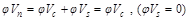 ACI 318-14 (Eq. 22.5.1.1)
Where:
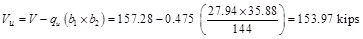
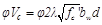 ACI 318-14 (Eq. 22.5.5.1)
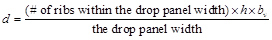
One-way shear capacity
is calculated assuming the shear cross-section area consisting of the drop
panel (if any), the ribs, and the slab portion above them, decreased by
concrete cover. For such section the equivalent shear width for single rib is
calculated from the formula:
 spSlab
Software Manual (Eq. 2-13)
spSlab
Software Manual (Eq. 2-13)
Where:
b = rib width, in.
d = distance from extreme compression fiber
to tension reinforcement centroid.
 for
middle span with #6 reinforcement.
for
middle span with #6 reinforcement.
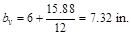


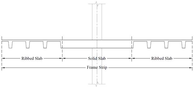
Figure 16 – Frame strip cross section (at distance d from
the face of the supporting column)
The one-way shear capacity for the ribbed slab
portions shown in Figure 16 is permitted to be increased by 10%. ACI 318-14 (9.8.1.5)


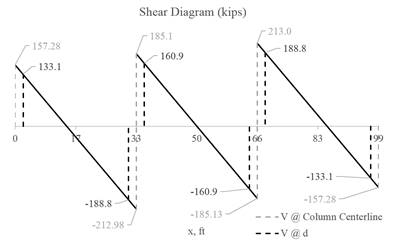
Figure 17 – One-way shear at critical sections (at distance d
from the face of the supporting column)
for
middle span with #6 reinforcement.

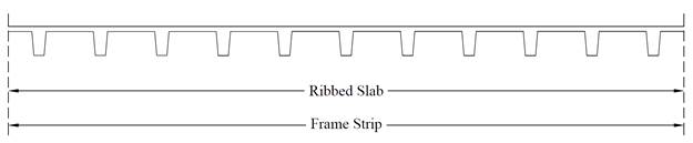
Figure 18 – Frame strip cross section (at distance d from
the face of the supporting column)
The one-way shear capacity for the ribbed slab
portions shown in Figure 15 is permitted to be increased by 10%. ACI 318-14 (9.8.1.5)

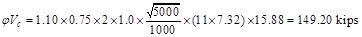

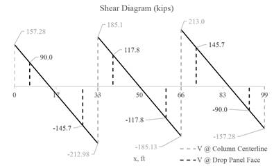
Figure 19 – One-way shear at critical sections (at the face of
the drop panel)
ACI
318-14 (22.6)
Two-way shear is critical on
a rectangular section located at d/2 away from the face of the column as
shown in Figure 14.
a. Exterior column:
The
factored shear force (Vu) in the critical section is computed
as the reaction at the centroid of the critical section minus the self-weight
and any superimposed surface dead and live load acting within the critical
section (d/2 away from column face).
The factored
unbalanced moment used for shear transfer, Munb, is computed
as the sum of the joint moments to the left and right. Moment of the vertical
reaction with respect to the centroid of the critical section is also taken
into account.

For the exterior
column in Figure 13, the location of the centroidal axis z-z is:

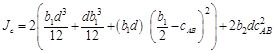
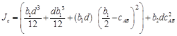
The
polar moment Jc of the shear perimeter is:
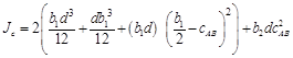

 ACI 318-14 (Eq. 8.4.4.2.2)
The
length of the critical perimeter for the exterior column:

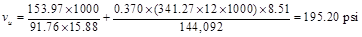
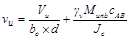
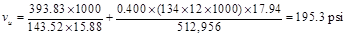
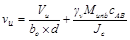
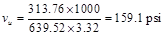
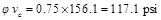
The
two-way shear stress (vu) can then be calculated as:
 ACI 318-14 (R.8.4.4.2.3)
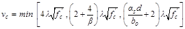
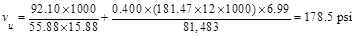
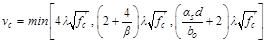 ACI 318-14 (Table 22.6.5.2)


b. Interior column:


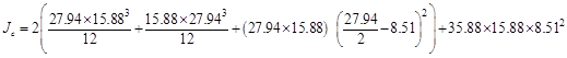
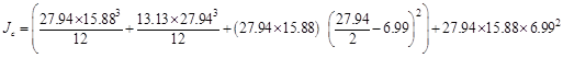
For
the interior column in Figure 13, the location of the centroidal axis z-z is:
The
polar moment Jc of the shear perimeter is:


 ACI 318-14 (Eq. 8.4.4.2.2)
The
length of the critical perimeter for the interior column:
The
two-way shear stress (vu) can then be calculated as:
 ACI 318-14 (R.8.4.4.2.3)
 ACI 318-14 (Table 22.6.5.2)

c. Corner column:
In
this example, interior equivalent frame strip was selected where it only have
exterior and interior supports (no corner supports are included in this strip).
However, the two-way shear strength of corner supports usually governs. Thus,
the two-way shear strength for the corner column in this example will be
checked for illustration purposes. The analysis procedure must be repeated for
the exterior equivalent frame strip to find the reaction and factored
unbalanced moment used for shear transfer at the centroid of the critical
section for the corner support.


For
the interior column in Figure 13, the location of the centroidal axis z-z is:

The
polar moment Jc of the shear perimeter is:

 ACI 318-14 (Eq. 8.4.4.2.2)
The
length of the critical perimeter for the corner column:
The two-way
shear stress (vu) can then be calculated as:
 ACI 318-14 (R.8.4.4.2.3)
 ACI 318-14 (Table 22.6.5.2)


Two-way
shear is critical on a rectangular section located at d/2 away from the
face of the drop panel.
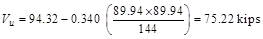
The
factored shear force (Vu) in the critical section is computed
as the reaction at the centroid of the critical section minus the self-weight
and any superimposed surface dead and live load acting within the critical
section (d/2 away from column face).
Note: For simplicity, it
is conservative to deduct only the self-weight of the slab and joists in the
critical section from the shear reaction in punching shear calculations. This
approach is also adopted in the spSlab program for the punching shear check
around the drop panels.
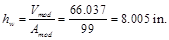
a. Exterior drop panel:

d that is used in the
calculation of vu is given by (see Figure 20):
 spSlab
Software Manual (Eq. 2-14)
spSlab
Software Manual (Eq. 2-14)
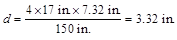
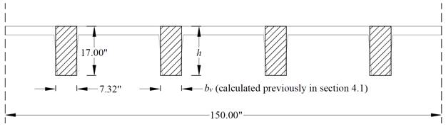
Figure 20 – Equivalent thickness based on shear area calculation
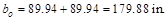
The
length of the critical perimeter for the exterior drop panel:
The
two-way shear stress (vu) can then be calculated as:
 ACI 318-14 (R.8.4.4.2.3)
The two-way shear capacity for the ribbed slab is
permitted to be increased by 10%. ACI 318-14 (9.8.1.5)
 ACI 318-14 (Table 22.6.5.2)


In waffle slab design where the
drop panels create a large critical shear perimeter, the factor (bo/d)
has limited contribution and is traditionally neglected for simplicity and conservatism.
This approach is adopted in this calculation and
in the spSlab program (spSlab software manual, Eq. 2-46).
The two-way shear capacity for the ribbed slab is
permitted to be increased by 10%. ACI 318-14 (9.8.1.5)


b. Interior drop panel:

The
length of the critical perimeter for the interior drop panel:
The
two-way shear stress (vu) can then be calculated as:
ACI 318-14 (R.8.4.4.2.3)
The two-way shear capacity for the ribbed slab is
permitted to be increased by 10%. ACI 318-14 (9.8.1.5)
ACI 318-14 (Table 22.6.5.2)


spSlab Software Manual (Eq. 2-46)


c. Corner drop panel:
The
length of the critical perimeter for the corner drop panel:
The
two-way shear stress (vu) can then be calculated as:
ACI 318-14 (R.8.4.4.2.3)
The two-way shear capacity for the ribbed slab is
permitted to be increased by 10%. ACI 318-14 (9.8.1.5)
ACI 318-14 (Table 22.6.5.2)


spSlab Software Manual (Eq. 2-46)
To mitigate the deficiency in
two-way shear capacity an evaluation of possible options is required:
1.
Increase the
thickness of the slab system
2.
Increasing the
dimensions of the drop panels (length and/or width)
3.
Increasing the
concrete strength
4.
Reduction of the
applied loads
5.
Reduction of the
panel spans
6.
Using less
conservative punching shear allowable (gain of 5-10%)
7.
Refine the
deduction of drop panel weight from the shear reaction (gain of 2-5%)
This example will be continued without the
required modification discussed above to continue the illustration of the
analysis and design procedure.
Since the slab thickness was
selected to meet the minimum slab thickness tables in ACI 318-14, the
deflection calculations of immediate and time-dependent deflections are not required.
They are shown below for illustration purposes and comparison with spSlab
software results.
The
calculation of deflections for two-way slabs is challenging even if linear
elastic behavior can be assumed. Elastic analysis for three service load levels
(D, D + Lsustained, D+LFull) is used to obtain immediate
deflections of the two-way slab in this example. However, other procedures may
be used if they result in predictions of deflection in reasonable agreement
with the results of comprehensive tests. ACI
318-14 (24.2.3)
The
effective moment of inertia (Ie) is used to account for the
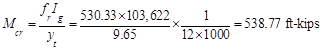
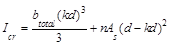
cracking effect on the flexural stiffness of the slab. Ie for
uncracked section (Mcr > Ma) is equal to Ig.
When the section is cracked (Mcr < Ma), then
the following equation should be used:
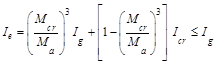 ACI 318-14 (Eq. 24.2.3.5a)
Where:
Ma = Maximum moment in member due to service loads at stage deflection is
calculated.
The
values of the maximum moments for the three service load levels are calculated
from structural analysis as shown previously in this document. These moments are
shown in Figure 17.
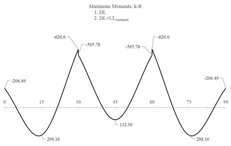
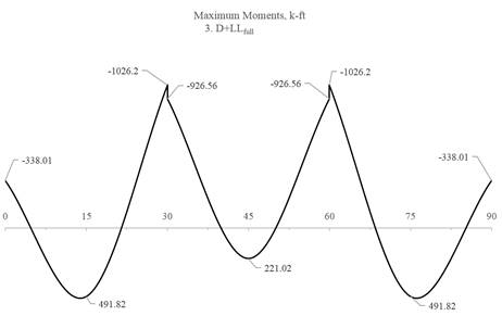
Figure 21 – Maximum Moments for the Three Service Load Levels
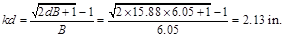
For positive moment (midspan) section:

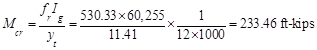 ACI
318-14 (Eq. 24.2.3.5b)
ACI
318-14 (Eq. 24.2.3.5b)

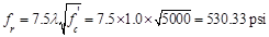 ACI
318-14 (Eq. 19.2.3.1)
ACI
318-14 (Eq. 19.2.3.1)

yt = Distance from centroidal axis
of gross section, neglecting reinforcement, to tension face, in.
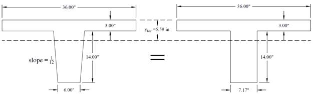
Figure 22 – Equivalent gross section for one rib - positive moment
section
 PCA Notes on ACI 318-11 (9.5.2.2)
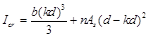
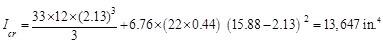
As
calculated previously, the positive reinforcement for the middle span frame
strip is 22 #6 bars located at 1.125 in. along the section from the bottom of
the slab. Figure 23 shows all the parameters needed to calculate the moment of
inertia of the cracked section transformed to concrete at midspan.
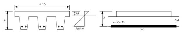
Figure 23 – Cracked Transformed Section - positive moment section

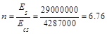
 ACI
318-14 (19.2.2.1.a)
ACI
318-14 (19.2.2.1.a)
 PCA Notes on ACI 318-11 (Table 10-2)
 PCA
Notes on ACI 318-11 (Table 10-2)
PCA
Notes on ACI 318-11 (Table 10-2)
 PCA Notes on ACI
318-11 (Table 10-2)
PCA Notes on ACI
318-11 (Table 10-2)
 PCA
Notes on ACI 318-11 (Table 10-2)
PCA
Notes on ACI 318-11 (Table 10-2)
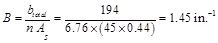
For negative moment section (near the interior
support of the end span):
The
negative reinforcement for the end span frame strip near the interior support
is 45 #6 bars located at 1.125 in. along the section from the top of the slab.
 ACI
318-14 (Eq. 24.2.3.5b)
ACI
318-14 (Eq. 24.2.3.5b)
ACI
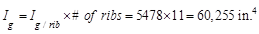
318-14 (Eq. 19.2.3.1)
Note: A lower value of Ig
(60,255 in.4) excluding the drop panel is conservatively adopted in
calculating waffle slab deflection by the spSlab software.

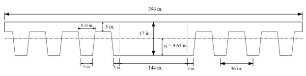
Figure 24 – Gross section – negative moment section
 ACI
318-14 (19.2.2.1.a)
ACI
318-14 (19.2.2.1.a)
PCA Notes on ACI 318-11 (Table 10-2)
 PCA
Notes on ACI 318-11 (Table 10-2)
PCA
Notes on ACI 318-11 (Table 10-2)

 PCA Notes on
ACI 318-11 (Table 10-2)
PCA Notes on
ACI 318-11 (Table 10-2)
 PCA
Notes on ACI 318-11 (Table 10-2)
PCA
Notes on ACI 318-11 (Table 10-2)
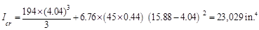
Note: A lower value of Icr
(18,722 in.4) excluding the drop panel is conservatively adopted in
calculating waffle slab deflection by the spSlab software.
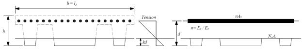
Figure 25 – Cracked transformed section - negative moment section
The
effective moment of inertia procedure described in the Code is considered
sufficiently accurate to estimate deflections. The effective moment of inertia,
Ie, was developed to provide a transition between the upper
and lower bounds of Ig and Icr as a
function of the ratio Mcr/Ma. For conventionally
reinforced (nonprestressed) members, the effective moment of inertia, Ie,
shall be calculated by Eq. (24.2.3.5a) unless obtained by a more comprehensive
analysis.
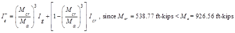
Ie
shall be permitted to be taken as the
value obtained from Eq. (24.2.3.5a) at midspan for simple and continuous spans,
and at the support for cantilevers. ACI
318-14 (24.2.3.7)
For
continuous one-way slabs and beams. Ie shall be permitted to
be taken as the average of values obtained from Eq. (24.2.3.5a) for the
critical positive and negative moment sections. ACI
318-14 (24.2.3.6)
For the middle span
(span with two ends continuous) with service load level (D+LLfull):
ACI
318-14 (24.2.3.5a)
Where Ie-
is the effective moment of inertia for the critical negative moment
section (near the support).

Where Ie+
is the effective moment of inertia for the critical positive moment section
(midspan).
Since
midspan stiffness (including the effect of cracking) has a dominant effect on
deflections, midspan section is heavily represented in calculation of Ie
and this is considered satisfactory in approximate deflection calculations.
Both the midspan stiffness (Ie+) and averaged span
stiffness (Ie,avg) can be used in the calculation of
immediate (instantaneous) deflection.
The averaged effective
moment of inertia (Ie,avg) is given by:
 PCA Notes on ACI 318-11 (9.5.2.4(2))
 PCA
Notes on ACI 318-11 (9.5.2.4(1))
PCA
Notes on ACI 318-11 (9.5.2.4(1))
However,
these expressions lead to improved results only for continuous prismatic
members. The drop panels in this example result in non-prismatic members
and the following expressions are recommended according to ACI 318-89:
 ACI
435R-95 (2.14)
ACI
435R-95 (2.14)
For the middle span
(span with two ends continuous) with service load level (D+LLfull):

 ACI
435R-95 (2.14)
ACI
435R-95 (2.14)
For the end span (span
with one end continuous) with service load level (D+LLfull):

Where:


Note: The prismatic member equations
excluding the effect of the drop panel are conservatively adopted in
calculating waffle slab deflection by spSlab.
Table
6 provides a summary of the required parameters and calculated values needed
for deflections for exterior and interior spans.
|
Table
6 – Averaged Effective Moment of Inertia Calculations
|
|
For Frame
Strip
|
|
Span
|
zone
|
Ig,
in.4
|
Icr,
in.4
|
Ma,
kips-ft
|
Mcr,
k-ft
|
Ie,
in.4
|
Ie,avg,
in.4
|
|
D
|
D +
LLSus
|
D +
Lfull
|
D
|
D +
LLSus
|
D +
Lfull
|
D
|
D +
LLSus
|
D +
Lfull
|
|
Ext
|
Left
|
103622
|
15505
|
206.5
|
206.5
|
338.0
|
539
|
103622
|
103622
|
103622
|
62612
|
62612
|
29087
|
|
Midspan
|
60255
|
15603
|
298.2
|
298.2
|
491.8
|
276
|
50964
|
50964
|
23482
|
|
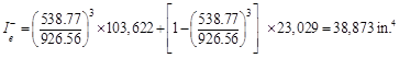
Right
|
103622
|
23029
|
626.6
|
626.6
|
1026.2
|
539
|
74259
|
74259
|
34692
|
|
Int
|
Left
|
103622
|
23029
|
565.8
|
565.8
|
926.6
|
539
|
92620
|
92620
|
38873
|
76437
|
76437
|
49564
|
|
Mid
|
60255
|
13647
|
132.6
|
132.6
|
221.0
|
276
|
60255
|
60255
|
60255
|
|
Right
|
103622
|
23029
|
565.8
|
565.8
|
926.6
|
539
|
92620
|
92620
|
38873
|
Deflections
in two-way slab systems shall be calculated taking into account size and shape
of the panel, conditions of support, and nature of restraints at the panel
edges. For immediate deflections in two-way slab systems, the midpanel deflection is computed as the sum of deflection at
midspan of the column strip or column line in one direction (Δcx
or Δcy) and deflection at midspan of the middle strip in
the orthogonal direction (Δmx or Δmy).
Figure 26 shows the deflection computation for a rectangular panel. The average
Δ for panels that have different properties in the two direction is
calculated as follows:
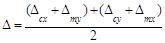 PCA
Notes on ACI 318-11 (9.5.3.4 Eq. 8)
PCA
Notes on ACI 318-11 (9.5.3.4 Eq. 8)
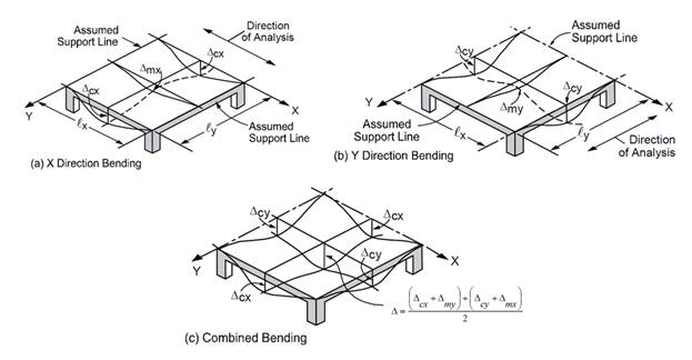
Figure 26 – Deflection Computation for a rectangular Panel
To calculate each
term of the previous equation, the following procedure should be used. Figure 27
shows the procedure of calculating the term Δcx. Same
procedure can be used to find the other terms.
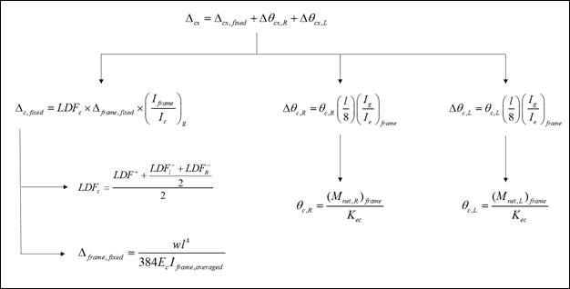
Figure 27 –Δcx calculation procedure
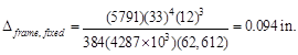
For end span - service
dead load case:
 PCA
Notes on ACI 318-11 (9.5.3.4 Eq. 10)
PCA
Notes on ACI 318-11 (9.5.3.4 Eq. 10)
Where:


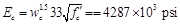 ACI
318-14 (19.2.2.1.a)
ACI
318-14 (19.2.2.1.a)
Iframe,averaged =
The averaged effective moment of inertia (Ie,avg)
for the frame strip for service dead load case from Table 6 = 62,612 in.4
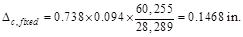
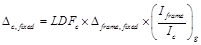 PCA
Notes on ACI 318-11 (9.5.3.4 Eq. 11)
PCA
Notes on ACI 318-11 (9.5.3.4 Eq. 11)
LDFc is the load distribution factor for the column strip.
The load distribution factor for the column strip can be found from the
following equation:
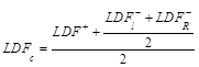 spSlab Software Manual (Eq. 2-114)
And the load
distribution factor for the middle strip can be found from the following
equation:
 spSlab Software Manual (Eq. 2-115)
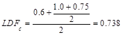
Taking
for example the end span where highest deflections are expected, the LDF for
exterior negative region (LDFL¯), interior negative region (LDFR¯), and
positive region (LDFL+)
are 1.00, 0.75, and 0.60, respectively (From Table
2 of this document). Thus, the load distribution factor for the column strip
for the end span is given by:
Ic,g = The gross moment of inertia (Ig) for
the column strip for service dead load = 28,289 in.4
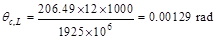
 PCA
Notes on ACI 318-11 (9.5.3.4 Eq. 12)
PCA
Notes on ACI 318-11 (9.5.3.4 Eq. 12)
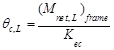
Where:
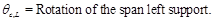

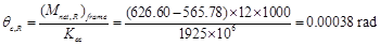
Kec = effective column stiffness = 1925
x 106 in.-lb (calculated previously).
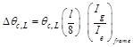 PCA
Notes on ACI 318-11 (9.5.3.4 Eq. 14)
PCA
Notes on ACI 318-11 (9.5.3.4 Eq. 14)
Where:

Where


Where:

 PCA
Notes on ACI 318-11 (9.5.3.4 Eq. 9)
PCA
Notes on ACI 318-11 (9.5.3.4 Eq. 9)

Following
the same procedure, Δmx can be calculated for the middle
strip. This procedure is repeated for the equivalent frame in the orthogonal
direction to obtain Δcy, and Δmy
for the end and middle spans for the other load levels (D+LLsus
and D+LLfull).
Since
this example has square panels, Δcx = Δcy=
0.222 in. and Δmx = Δmy=
0.128 in.
The
average Δ for the corner panel is calculated as follows:

The calculated deflection can now be compared with
the applicable limits from the governing standards or project specified limits
and requirements. Optimization for further savings in materials or construction
costs can be now made based on permissible deflections in lieu of accepting the
minimum values stipulated in the standards to avoid deflection calculations.