1. C-Shaped Core Wall Biaxial Strength Calculations
The following three figures display the section’s strain diagram, internal forces and the corresponding moment arms in the necessary nomenclature to prepare for the strength calculations of each of the following:
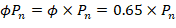
Figure 3 shows the strain diagram for the reinforcement and concrete based on the neutral axis location and angle values provided. The internal forces for the reinforcement and concrete compression block are calculated based on the strain values. φ is calculated based on the strain in the extreme tension reinforcement layer.
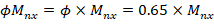
• Design Flexural Strength (φMnx)
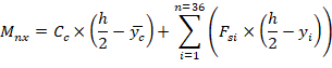
The flexural strength φMnx can be calculated using force values and moment arms from the x-axis (ry) as shown in Figure 4.
• Design Flexural Strength (φMny)
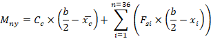
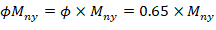
The flexural strength φMny can be calculated using force values and moment arms from the y-axis (rx) as shown in Figure 5.
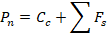
Figure 3 - Design Axial Strength (φPn) Calculations
Figure 4 - Design Flexural Strength (φMnx) Calculations
Figure 5 - Design Flexural Strength (φMny) Calculations
1.1. Neutral Axis Location and Concrete Compression Force
The trial-and-error process for calculating the neutral axis depth and angle α is not required in this example since these values are given (c = 36.12 in. and α = 120o) . Where c is the distance from the fiber of maximum compressive strain to the neutral axis and α is the angle of the neutral axis. ACI 318-19 (22.2.2.4.2)


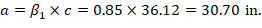

a = Depth of equivalent rectangular stress block

 (Compression) ACI 318-19 (22.2.2.4.1)
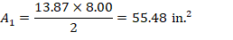
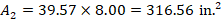
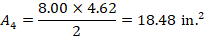
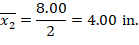
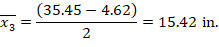
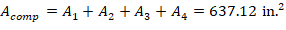
Calculate the area of the section subject to compression and its centroid by examining the four sub segments as shown in the following figure:


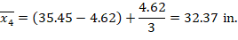
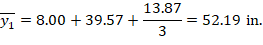
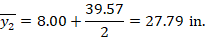
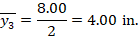
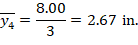
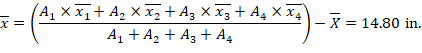
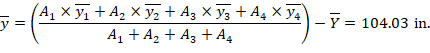
Note that  and
and  are the coordinates of the centroid of the entire cross-section (uncracked core wall section).
Figure 6 - Cracked Concrete Wall Section Centroid Calculations
1.2. Determination of Reinforcement Strains and Forces
The following shows the calculations of forces in the reinforcement layers with the extreme tension (at bar 1) and extreme compression (at bar 29) strains. The calculations for the rest of layers are shown the table at the end of this section.
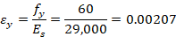
For extreme tension reinforcement layer (at bar 1):


For extreme compression reinforcement layer (at bar 29):

The area of the reinforcement in this layer is included in the area used to compute Cc (a = 30.70 in. > d29 = 5.40 in.). As a result, it is necessary to subtract 0.85fc’ from fs29 before computing Fs29:

The same procedure shown above can be repeated to calculate the forces in the remaining reinforcement locations, results are summarized in the table shown in the next page:
1.3. Calculation of Pn, Mnx and Mny