1. Concrete Column Biaxial Strength Calculations

06

Figure 4 - Strains, Forces, and Moment Arms Diagram

1.1. Location of Neutral Axis and Concrete Compression Force

Use and iterative procedure to determine the nominal moment capacities for a point where the nominal axial load capacity, Pn, = 426 kips and Mnx/Mny = 1.60.

Several previous trials are conducted to determine the c value and the angle α. The following shows the last trial:

Try c = 12.50 in. and α = 43.9o, where c is the distance from the fiber of maximum compressive strain to the neutral axis and α is the angle of the neutral axis.     ACI 318-19 (22.2.2.4.2)


    ACI 318-19 (Table 21.2.2)

    ACI 318-19 (22.2.2.4.1)

    ACI 318-19 (22.2.2.1)

Where:

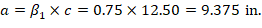
a = Depth of equivalent rectangular stress block

    ACI 318-19 (Table 22.2.2.4.3)

   (Compression) ACI 318-19 (22.2.2.4.1)

Where:


(see the following figure)

07

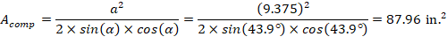
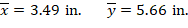
Figure 5 - Cracked Concrete Column Section Centroid Calculations

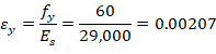
1.2. Strains and Forces Determination in Reinforcement Layers

For the 1st reinforcement layer:


(Tension)

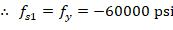
For the 9th reinforcement layer:


The area of the reinforcement in this layer is included in the area used to compute Cc (a = 9.38 in. > d9 = 7.14 in.). As a result, it is necessary to subtract 0.85fc from fs9 before computing Fs9:

(Compression)

The same procedure shown above can be repeated to calculate the forces in the remaining reinforcement locations, results are summarized in the following table:

Table 1 - Strains, internal force resultants and Moments

Location

d, in

ε, in./in.

fs, psi

Fs, kip

Cc, kip

Moment arm (x), in.

My, kip-ft

Moment arm (y), in.

Mx, kip-ft

Concrete

---

0.00300

---

---

448.57

3.49

130.46

5.66

211.58

Bar 1

21.97

-0.00227

-60000

-47.40

---

-5.50

21.73

-7.50

29.63

Bar 2

18.37

-0.00141

-40841

-32.26

---

-5.50

14.79

-2.50

6.72

Bar 3

14.77

-0.00054

-15764

-12.45

---

-5.50

5.71

2.50

-2.59

Bar 4

11.16

0.00032

9312

7.36

---

-5.50

-3.37

7.50

4.60

Bar 5

18.16

-0.00136

-39373

-31.10

---

0.00

0.00

-7.50

19.44

Bar 6

7.35

0.00124

35851

24.29*

---

0.00

0.00

7.50

15.18

Bar 7

14.34

-0.00044

-12827

-10.13

---

5.50

-4.64

-7.50

6.33

Bar 8

10.74

0.00042

12250

9.68

---

5.50

4.44

-2.50

-2.02

Bar 9

7.14

0.00129

37320

25.45*

---

5.50

11.66

2.50

5.30

Bar 10

3.53

0.00215

60000

43.37*

---

5.50

19.88

7.50

27.11

Axial Force and Bending Moment

Pn, kip

425.37

Mny, kip-ft

200.64

Mnx, kip-ft

321.28

ϕPn, kip

283.72

ϕMny, kip-ft

133.83

ϕMnx, kip-ft

214.29

* The area of the reinforcement in this layer has been included in the area used to compute Cc. As a result, 0.85fc is subtracted from fs in the computation of Fs.


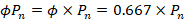
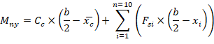
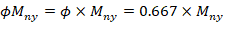
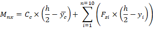
1.3. Calculation of Pn, Mnx and Mny


(+) = Compression

(-) = Tension


(+) = Counter Clockwise

(-) = Clockwise


(+) = Counter Clockwise

(-) = Clockwise


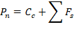
Since the calculated Pn, and Mnx/Mny are equal to the given Pn, and Mnx/Mny (Pn, = 426 kip and Mnx/Mny = 321/201 = 1.60), the assumptions that c = 12.5 in. and α = 43.9º are verified as correct.