Biaxial Bending Interaction Diagrams for Spiral Reinforced Circular Concrete Column Design (ACI 318-19)
Biaxial bending of columns occurs when the loading causes bending simultaneously about both principal axes. The commonly encountered case of such loading occurs in corner columns. Corner and other columns exposed to known moments about each axis simultaneously should be designed for biaxial bending and axial load.
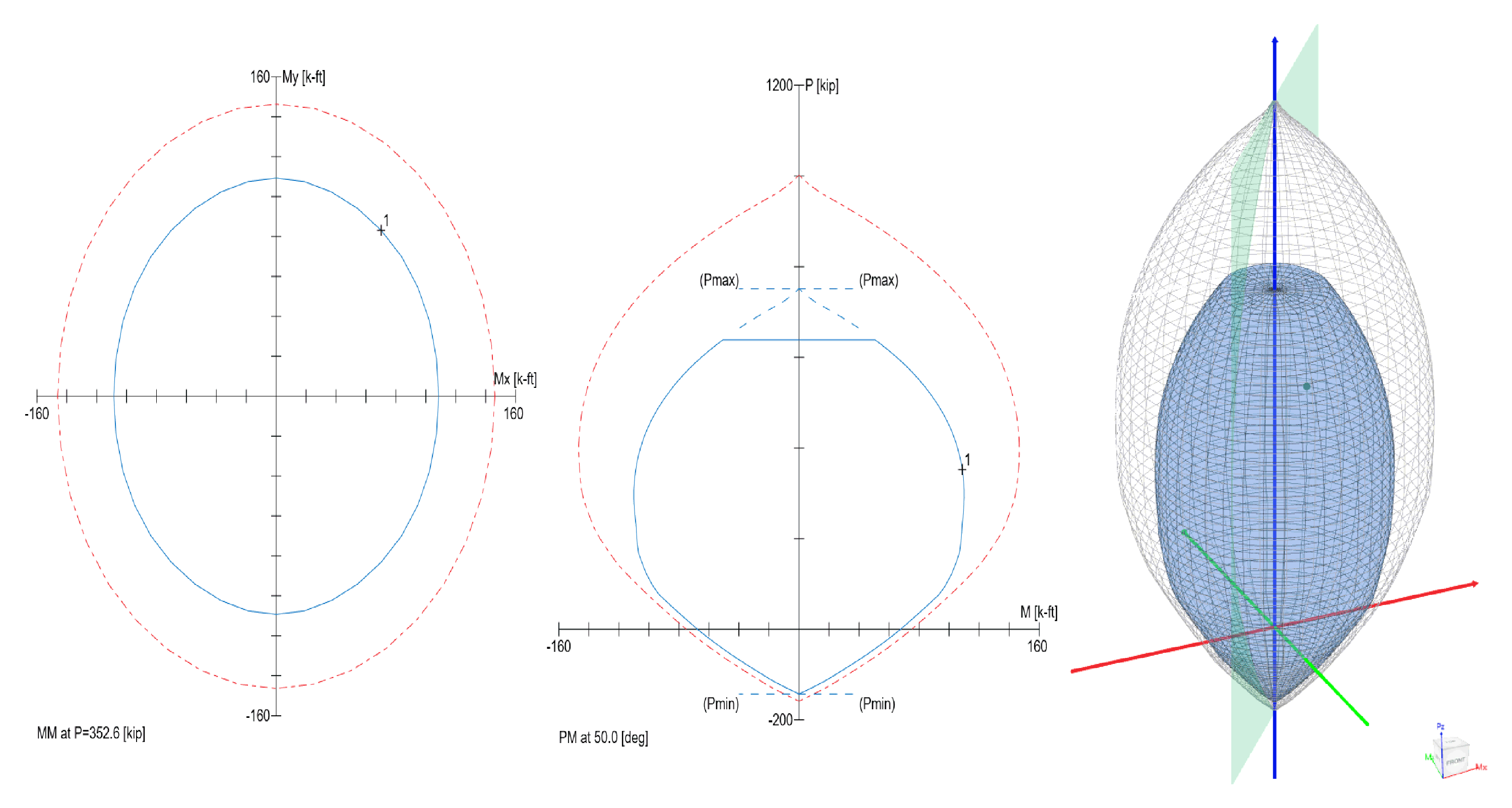
A uniaxial interaction diagram defines the load-moment strength along a single plane of a section under an axial load P and a uniaxial moment M. The biaxial bending resistance of an axially loaded column can be represented schematically as a surface formed by a series of uniaxial interaction curves drawn radially from the P axis. Data for these intermediate curves are obtained by varying the angle of the neutral axis (for assumed strain configurations) with respect to the major axes.
The difficulty associated with the determination of the strength of reinforced columns subjected to combined axial load and biaxial bending is primarily an arithmetic one. The bending resistance of an axially loaded column about a particular skewed axis is determined through iterations involving simple but lengthy calculations. These extensive calculations are compounded when optimization of the reinforcement or cross-section is sought.
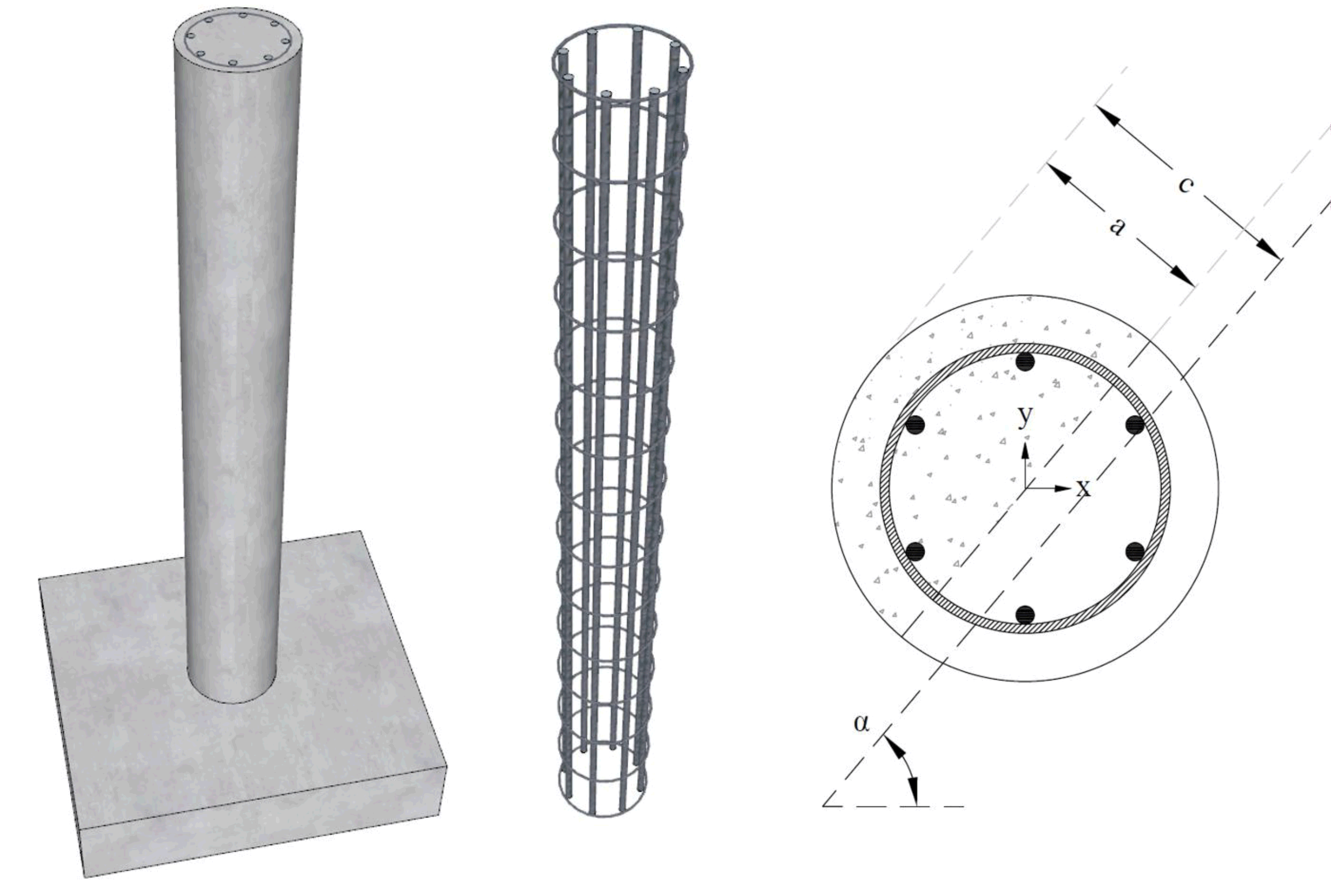
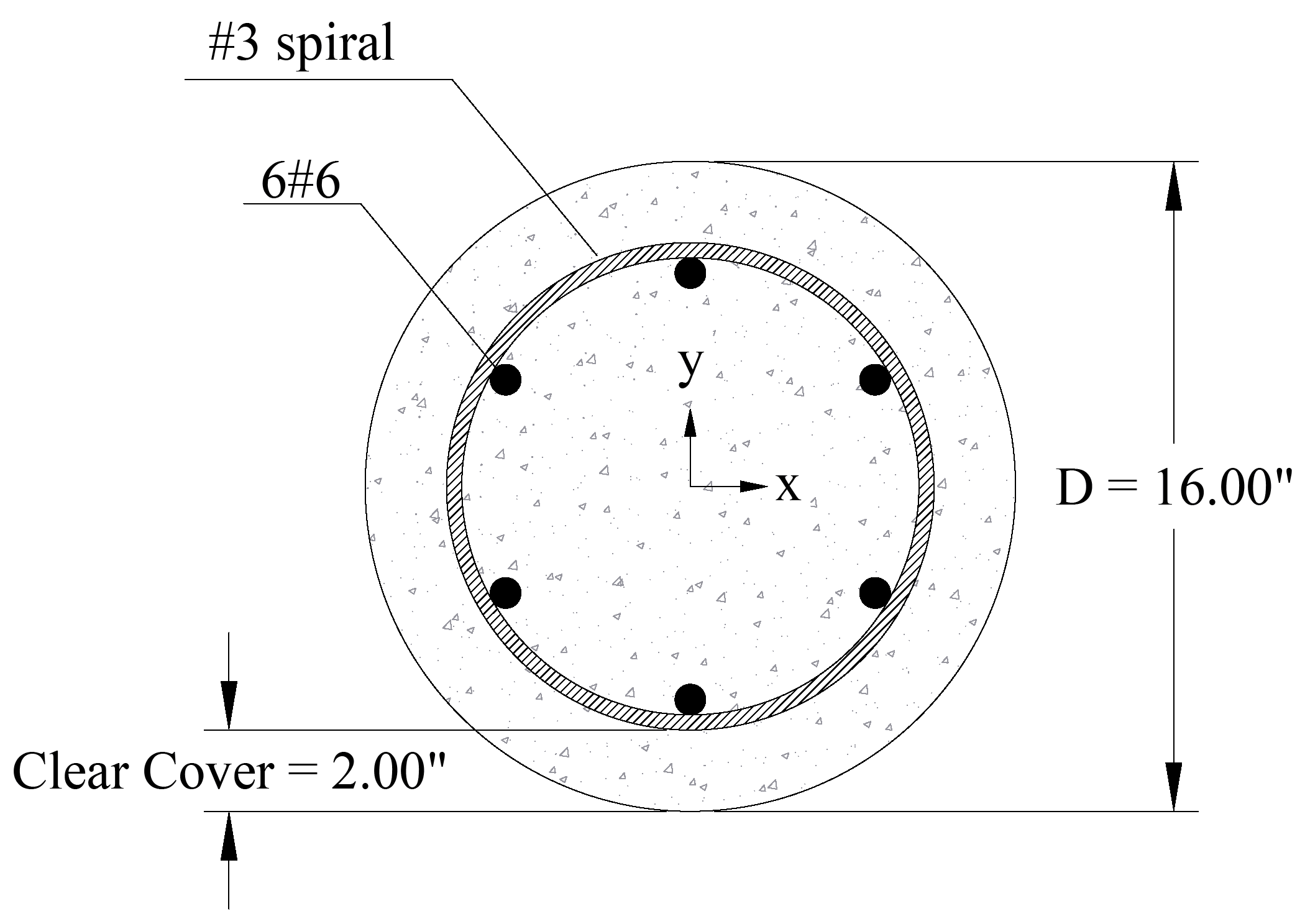
This example demonstrates the determination of the design axial load capacity, φPn, and the design φMnx and φMny moments corresponding to the following case: The neutral axis depth of 10.05 in., at an angle of 50º counterclockwise from the x-axis of the cross section. The figure below shows the reinforced concrete circular column cross section in consideration. The calculated values of the column axial strength and biaxial bending strength are compared with the exact values from spColumn engineering software program from StructurePoint.
The steps to develop the three-dimensional failure surface (interaction diagram) using spColumn will be shown in details as well.


