Building Code Requirements for Structural Concrete (ACI 318-19) and Commentary (ACI 318R-19)
• spColumn Engineering Software Program Manual v10.00, STRUCTUREPOINT, 2021
• “Biaxial Bending Interaction Diagrams for Square Reinforced Concrete Column Design (ACI 318-19)” Design Example, STRUCTUREPOINT, 2022
• “Biaxial Bending Interaction Diagrams for Rectangular Reinforced Concrete Column Design (ACI 318-19)” Design Example, STRUCTUREPOINT, 2022
• “Biaxial Bending Interaction Diagrams for C-Shaped Concrete Core Wall Design (ACI 318-19)” Design Example, STRUCTUREPOINT, 2022
• “Manual Design Procedure for Columns and Walls with Biaxial Bending (ACI 318-11-14-19)” Design Example, STRUCTUREPOINT, 2022
Column dimensions and reinforcement locations are shown in following figure.
Figure 2 - Reinforced Concrete Column Cross-Section and Reinforcement Locations
In a reinforced concrete column, the determination of the nominal axial load capacity, Pn, and the nominal Mnx and Mny moments involves a trial-and-error process for calculating the neutral axis depth and angle α. In this example, the neutral axis depth and angle are provided as an input (c = 10.05 in. and an angle of α = 50º) for illustration.
The steps to calculate biaxial flexural strength of a circular reinforced concrete column for nominal axial strength and biaxial bending moments are as follows:
1. Use the provided values for the angle of the neutral axis (α) and the neutral axis depth (c) to calculate the strain values in each reinforcement layer
2. Calculate the forces values in the concrete (Cc) and reinforcement layers (Fsi)
3. Calculate Pn, Mnx and Mny using the following equations

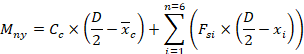
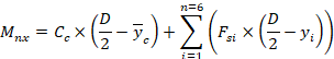
The following figure demonstrates the procedure explained above:
Figure 3 - Nominal Axial Load and Biaxial Flexural Strength Calculation Methods for a Reinforced Concrete Columns