1. Concrete Column Biaxial Strength Calculations
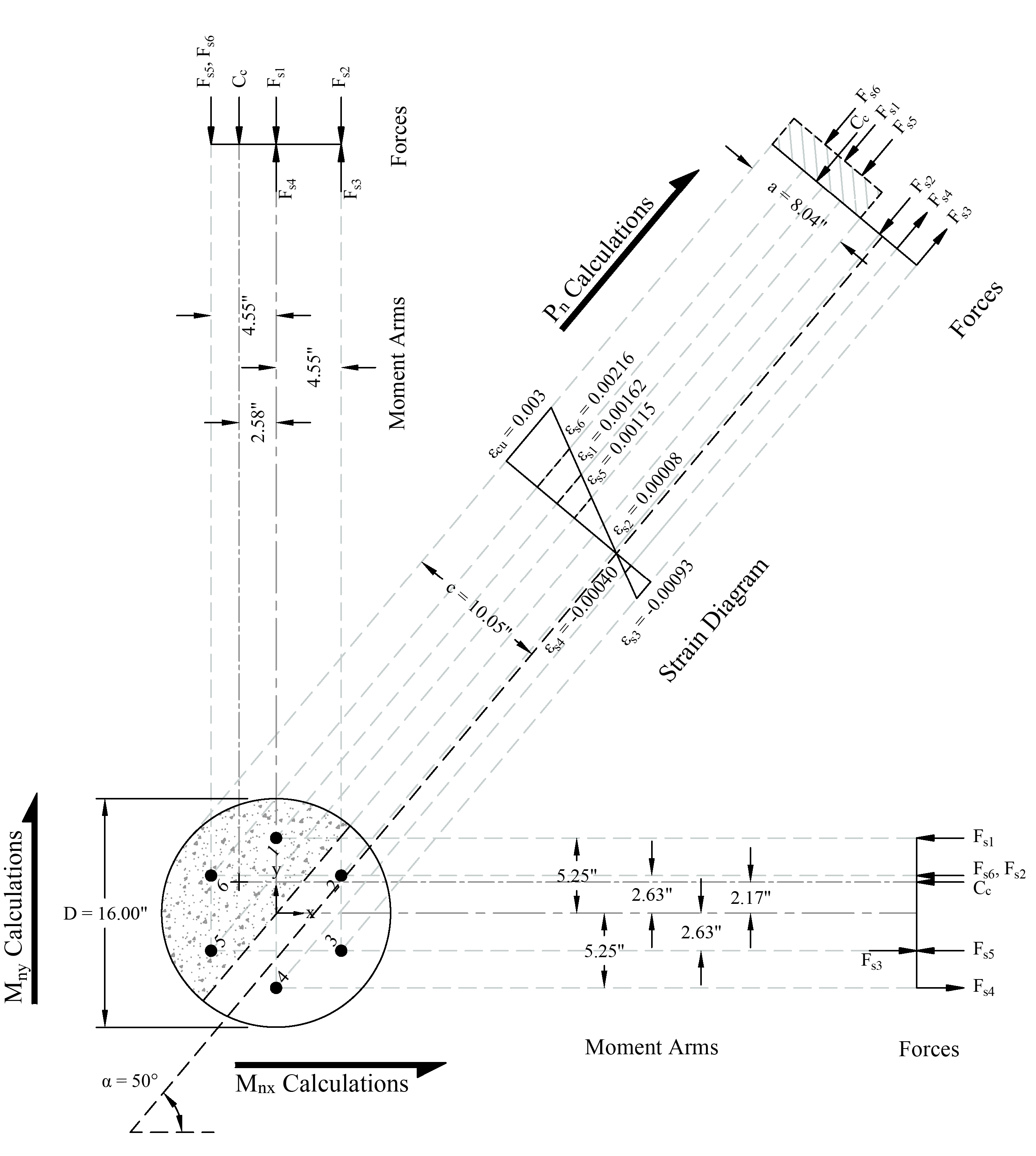
Figure 4 - Strains, Forces, and Moment Arms Diagram
1.1. Location of Neutral Axis and Concrete Compression Force
The trial-and-error process for calculating the neutral axis depth and angle α is not required in this example since these values are given (c = 10.05 in. and α = 50o). Where c is the distance from the fiber of maximum compressive strain to the neutral axis and α is the angle of the neutral axis. ACI 318-19 (22.2.2.4.2)

 (for spiral) ACI 318-19 (Table 21.2.2)
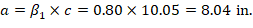

a = Depth of equivalent rectangular stress block

 (Compression) ACI 318-19 (22.2.2.4.1)
Where (see the following figure):
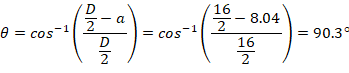
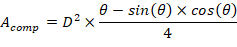
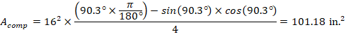
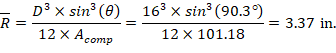

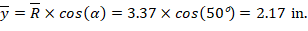
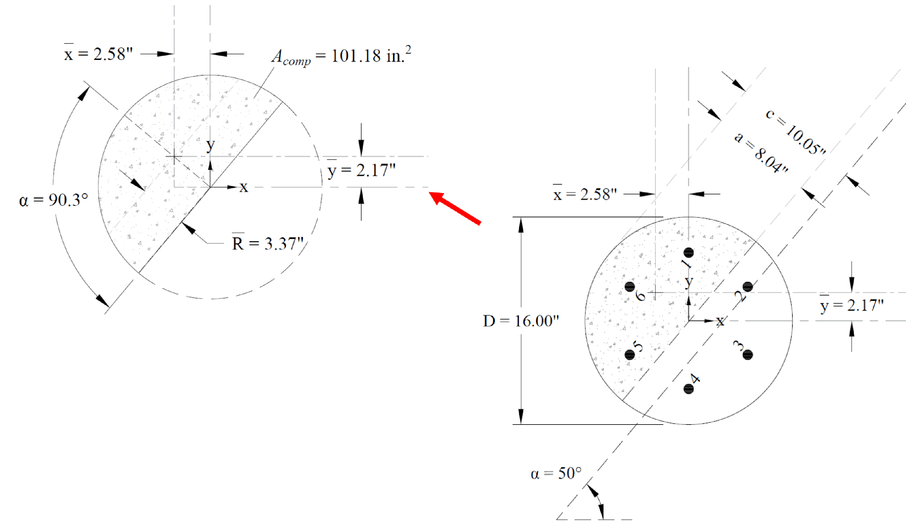
Figure 5 - Cracked Concrete Column Section Centroid Calculations
1.2. Strains and Forces Determination in Reinforcement Layers
The following shows the calculations of forces in the reinforcement layers with the extreme tension (at bar 3) and extreme compression (at bar 6) strains. The calculations for the rest of layers are shown the table at the end of this section.
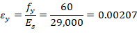
For extreme tension reinforcement layer (at bar 3):


For extreme tension reinforcement layer (at bar 6):


The area of the reinforcement in this layer is included in the area used to compute Cc (a = 8.04 in. > d6 = 2.83 in.). As a result, it is necessary to subtract 0.85fc’ from fs6 before computing Fs6:

The same procedure shown above can be repeated to calculate the forces in the remaining reinforcement locations, results are summarized in the following table:
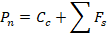
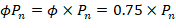
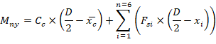
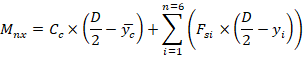
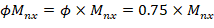
1.3. Calculation of Pn, Mnx and Mny