3. Bar Stress Near Tension Face Equal to 0.5 fy, (fs = 0.5 fy)
Figure 5 - Strains, Forces, and Moment Arms (fs = 0.5 fy)
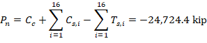
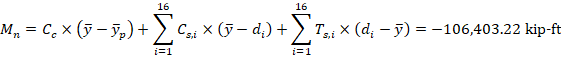
The following show the general procedure to calculate the axial and moment capacities of the core wall section at this control point, all the calculated values are shown in the next Table.
3.1. c, a, and strains in the reinforcement
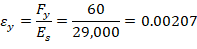


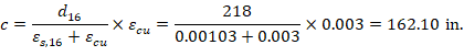
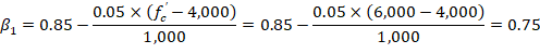
Where c is the distance from the fiber of maximum compressive strain to the neutral axis. ACI 318-19 (22.2.2.4.2)
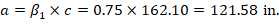
a = Depth of equivalent rectangular stress block
3.2. Forces in the concrete and steel
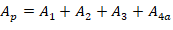
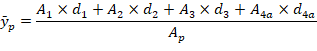
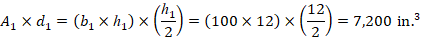
Since h1 + h2 + h3 + h4 = 208 in. > a = 121.58 in. > h1 + h2 + h3 = 116 in., the area and centroid of the concrete equivalent block (see Figure 2 and 5) can be found as follows:


If the reinforcement layer is located within the depth of the equivalent rectangular stress block (a), it is necessary to subtract 0.85fc’ from fs,i before computing Fs,i since the area of the reinforcement in this layer has been included in the area used to compute Cc.
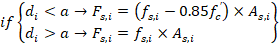
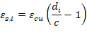
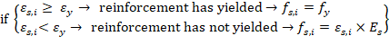
The force developed in the reinforcement layer (Fs,i) is considered as compression force (Cs,i) if the effective depth of this steel layer (di) is less than c (the distance from the fiber of maximum compressive strain to the neutral axis), otherwise it is considered as tension force (Ts,i).
Using values from the next Table: