Using 11.8 provisions, calculate factored loads as follows for each of the considered load combinations:
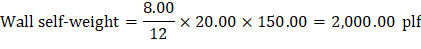
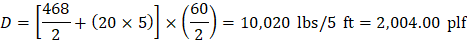
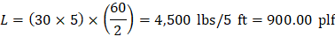
4.1. Roof Load per foot width of wall
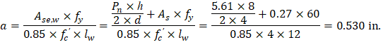
Figure 2 – Typical Geometry of 10DT24 Section

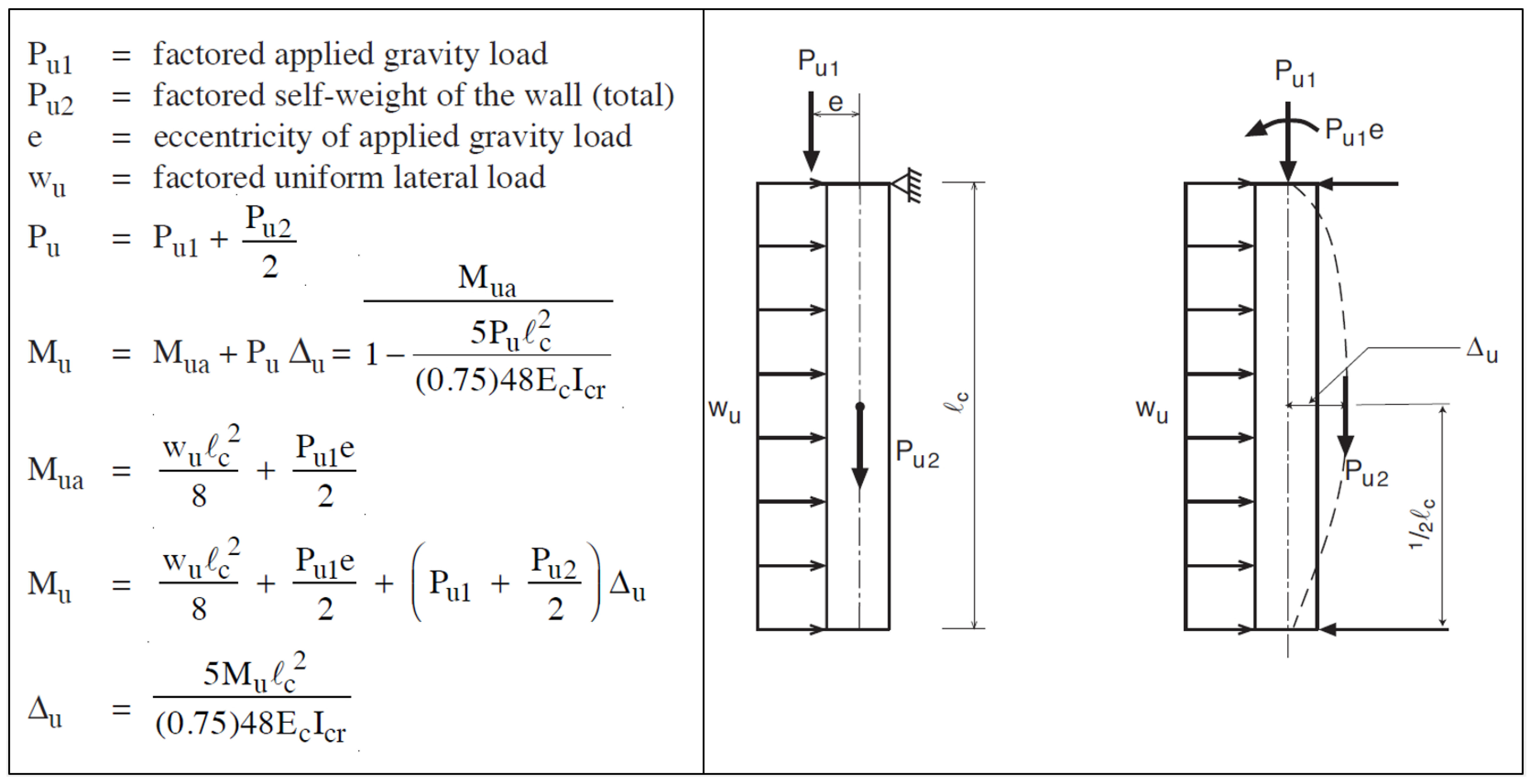
4.2. Calculation of Maximum Wall Forces
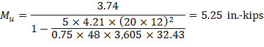
The calculation of maximum factored wall forces in accordance with 11.8 is summarized in Figure 3 including moment magnification due to second order (P-Δ) effects.
For load combination #1 (U = 1.4 D)
ACI 318-19 (11.8.3.1d)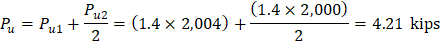
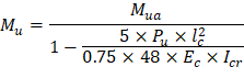

Where Mua is the maximum factored moment at midheight of wall due to lateral and eccentric vertical loads, not including PΔ effects.
ACI 318-19 (11.8.3.1)
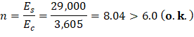
ACI 318-19 (19.2.2.1.b) ACI 318-19 (11.8.3.1c) ACI 318-19 (11.8.3.1)
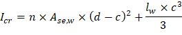
Calculate the effective area of longitudinal reinforcement in a slender wall for obtaining an approximate cracked moment of inertia.
ACI 318-19 (R11.8.3.1)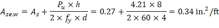
The following calculation are performed with the effective area of steel in lieu of the actual area of steel.
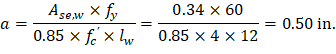
Figure 4 – 1 ft Wall Strip Cross-Section
ACI 318-19 (11.8.3.1c) ACI 318-19 (21.2.2.1) Therefore, section is tension controlled ACI 318-19 (Table 21.2.2) ACI 318-19 (Table 21.2.2) ACI 318-19 (11.8.3.1d)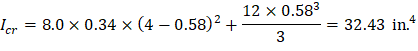


The steps above are repeated for all the considered load combinations, Table 1 shows the factored loads at mid-height of wall for all of these load combinations.
Pu (kips) | Mua (in.-kips) | Ec (ksi) | n | Ase,w (in.2/ft) | a (in.) | c (in.) | Icr (in.4) | εt (in./in.) | ϕ | Mu (in.-kips) | |
1.4 D | 4.21 | 3.74 | 3,605 | 8 | 0.34 | 0.50 | 0.58 | 32.4 | 0.0176 | 0.9 | 5.25 |
1.2 D + 1.6 Lr + 0.8 W | 5.04 | 19.53 | 3,605 | 8 | 0.35 | 0.52 | 0.61 | 33.4 | 0.0168 | 0.9 | 29.38 |
1.2 D + 0.5 Lr + 1.6 W | 4.05 | 32.61 | 3,605 | 8 | 0.33 | 0.49 | 0.58 | 32.3 | 0.0178 | 0.9 | 45.22 |
0.9 D + 1.6 W | 2.70 | 31.21 | 3,605 | 8 | 0.31 | 0.46 | 0.54 | 30.7 | 0.0193 | 0.9 | 38.80 |
4.3. Tension-Controlled Verification
ACI 318-19 (11.8.1.1(b))
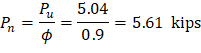
For this check use the largest Pu (5.04 kips) from load combination 2 to envelop all the considered combinations.
Therefore, section is tension controlled ACI 318-19 (Table 21.2.2)