5. Flexural, Shear, and Torsion Design
5.1. Flexural Design
For this beam, the moment at the fixed end governs the design as shown previously.
Mu = 228.25 kip-ft |
Use #8 bars with 1.50 in. concrete cover per ACI 318-14 (Table 20.6.1.3.1) and #4 stirrups. The distance from extreme compression fiber to the centroid of longitudinal tension reinforcement, d, is calculated below:
| |
|


To determine the area of steel, assumptions have to be made whether the section is tension or compression controlled, and regarding the distance between the resultant compression and tension forces along the beam section (jd). In this example, tension-controlled section will be assumed so the reduction factor ϕ is equal to 0.9, and jd will be taken equal to 0.9253 × d. The assumptions will be verified once the area of steel is finalized.
Assume jd = 0.9253 × d = 0.9253 × 21.50 = 19.89 in. | |
Beam width, b = 14.00 in. |
The required reinforcement at initial trial is calculated as follows:
| |
Recalculate ‘a’ for the actual As = 2.550 in.2: | |
| |
|


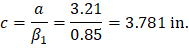
Where:
| ACI 318-14 (Table 22.2.2.4.3) |
| |
| |
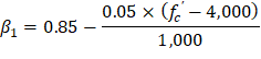


Therefore, the assumption that section is tension-controlled is valid.
|

The minimum reinforcement shall not be less than
| ACI 318-14 (9.6.1.2(a)) |

And not less than
| ACI 318-14 (9.6.1.2(b)) |
| |
| |

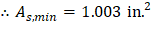

Torsion requirements for longitudinal steel have to be determined and combined with reinforcement area required for flexure.
Check if torsional effects can be neglected:
If Tu < ϕTth, it shall be permitted to neglect torsional effects. | ACI 318-14 (22.7.1.1) |
Where:
Tu = 28.00 kip-ft (Figure 2) | ACI 318-14 (Table 22.2.2.4.3) |
ϕTth = 5.87 kip-ft = Threshold torsion (the calculation of ϕTth is shown in the next section) | |
Since Tu > ϕTth, the torsional effects must be considered. |
Check if the factored design torsion can be reduced:
It is permitted to reduce Tu to ϕTcr; due to redistribution of internal forces after torsional cracking; if the exterior continuous beam meet the following requirements:
ACI 318-14 (22.7.3.2)
1. The beam is statically indeterminate (continuous beam).
2. Tu ≥ ϕTth.
The Torsion is needed for equilibrium; therefore, design for:
Tu = 28.00 kip-ft (Figure 2)
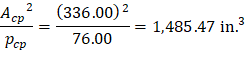
The torsional properties of the beam are the following:
| |
| |
| |
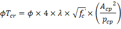
| ACI 318-14 (Table 22.7.5.1(a)) |
| |
|




5.2.1. Adequacy of Cross-Sectional Dimensions for Torsion
For solid sections, the limit on shear and torsion is given by:
| ACI 318-14 (22.7.7.1a) |

Using d = 21.50 in., the factored shear force at the critical section located at a distance d from the face of the support is:
Vu = 57.14 kip-ft (Figure 2)
Also, the nominal shear strength provided by the concrete is:
| ACI 318-14 (Eq. 22.5.5.1) |

Using a 1.50 in. clear cover to # 4 closed stirrups.
| |
| |
| |
| |
Therefore, the section is adequate. |




5.2.2. Transverse Reinforcement Required for Torsion
ACI 318-14 (Eq. 22.7.6.1a)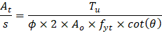
Where:
Ao = 0.85 × Aoh = 0.85 × 215.25 = 182.96 in.2 | ACI 318-14 (22.7.6.1.1) |
θ = 45 ̊ | ACI 318-14 (22.7.6.1.2(a)) |
Therefore,
|

5.2.3. Transverse Reinforcement Required for Shear
Vu = 57.14 kip-ft (Figure 2)
Shear strength provided by concrete
ACI 318-14 (Eq. 22.5.5.1) Since , Shear reinforcement is required. The nominal shear strength required to be provided by shear reinforcement is Check whether Vs is less than If Vs is greater than ACI 318-14 (22.5.1.2) Since Vs does not exceed Calculate the required transverse reinforcement for shear as ACI 318-14 (22.5.10.5.3)


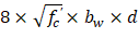
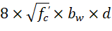 , then the cross-section has to be revised as ACI 318-14 limits the shear capacity to be provided by stirrups to
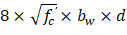

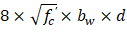 , the cross section is adequate.

5.2.4. Total Required Transverse Reinforcement for Combined Shear and Torsion
|

Minimum transverse reinforcement for shear and torsion is calculated as follows:
| ACI 318-14 (9.6.4.2) |
| |
| |
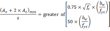



Calculate the required spacing:
Maximum spacing of transverse torsion reinforcement:
| ACI 318-14 (9.7.6.3.3) |
| |
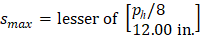

Maximum spacing of transverse shear reinforcement:
Check whether the required spacing based on the shear demand meets the spacing limits for shear reinforcement per ACI 318-14 (9.7.6.2.2).
Check whether Vs is less than | |
|
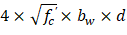

Therefore, maximum stirrup spacing shall be the smallest of d/2 and 24.00 in.
| ACI 318-14 (9.7.6.2.2) |
|
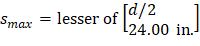

For #3 stirrups, Av+t (two legs) = 0.22 in.2, and the required s = 0.22 / 0.0704 = 3.13 in. < 10.75 in.
For #4 stirrups, Av+t (two legs) = 0.40 in.2, and the required s = 0.40 / 0.0704 = 5.69 in. < 10.75 in.
Use No. 4 closed stirrups at 5.00 in. on centers, placing the first stirrup at 2.50 in. from the face of the support.
5.2.5. Additional Required Longitudinal Reinforcement for Torsion
| ACI 318-14 (Eq. 22.7.6.1b) |
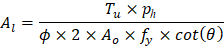
Where:
Ao = 0.85 × Aoh = 0.85 × 215.25 = 182.96 in.2 | ACI 318-14 (22.7.6.1.1) |
θ = 45 ̊ | ACI 318-14 (22.7.6.1.2(a)) |
Therefore,
|

The minimum total area of longitudinal torsional reinforcement:
| ACI 318-14 (9.6.4.3) |
| |
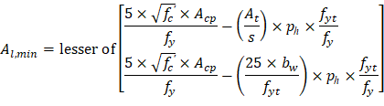
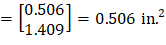
Since Al > Al,min, use Al = 1.265 in.2
The longitudinal reinforcement is to be distributed around the perimeter of the stirrups, with a maximum spacing of 12.00 in. There shall be at least one longitudinal bar in each corner of the stirrups.
ACI 318-14 (9.7.5.1)
Longitudinal bars shall have a diameter at least 0.042 times the stirrup spacing, but not less than 3/8 in.
ACI 318-14 (9.7.5.2)
Provide 4 - #4 bars in the lower portion of the beam (two at mid-depth and two at bottom) and add 1.265 in.2 (Section 5.2.5) - (4 × 0.20) = 0.465 in.2 to the flexural steel.
The total area of steel required in top face of the beam is 2.550 in.2 (Section 5.1) + 0.465 in.2 = 3.015 in.2. Thus, we have:
6 - #7 bars: As = 3.600 in.2, will not fit in one layer.
4 - #8 bars = As = 3.160 in.2, will fit in one layer.
Provide 4 - #8 bars at the top of the beam. (see Figure 4).
ACI 318-14 (9.5.4.5) allows a designer to subtract Mu / (0.9 × d × fy) from the area of longitudinal steel in the flexural compression zone. We shall not do this, for three reasons:
1. Mu varies along the length of the beam.
2. We need two bars of minimum diameter 0.21 in. in the corners of the stirrups.
3. We need bars to support the corners of the stirrups.
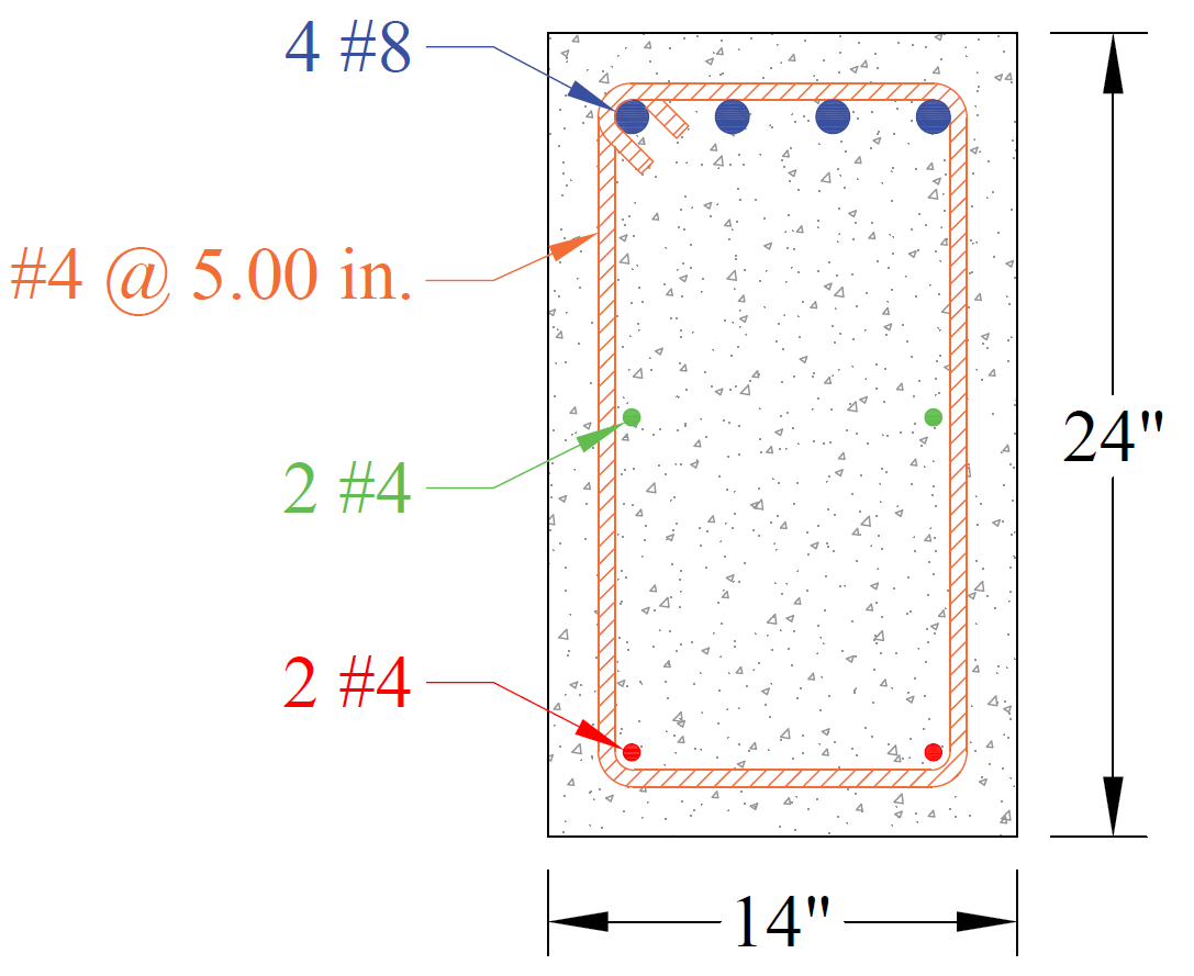
Figure 4 – Reinforced Concrete Cantilever Beam Cross Section