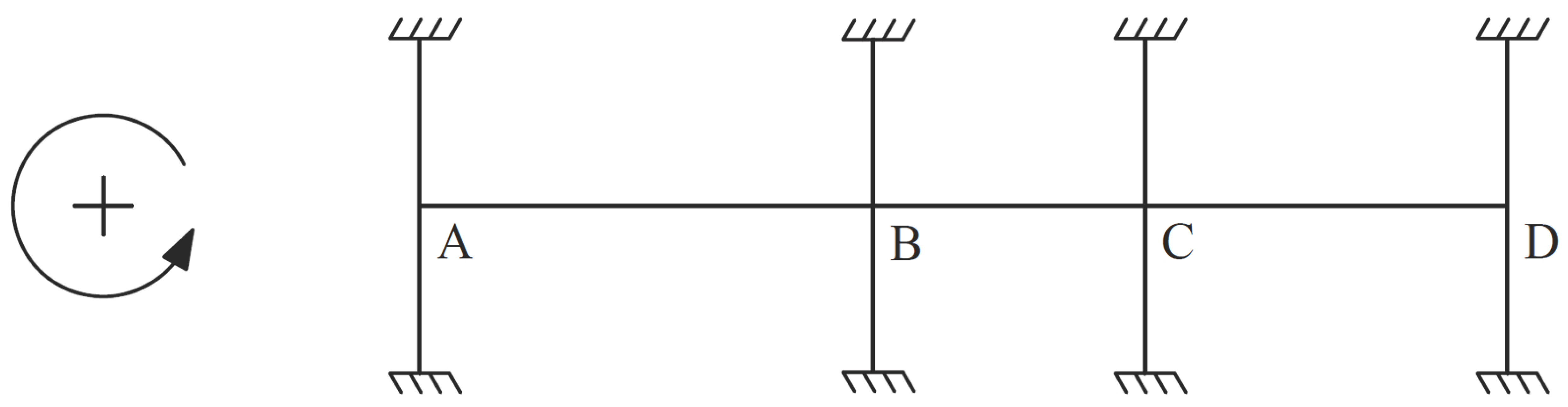
1. Continuous Beam Analysis - Moment Distribution Method
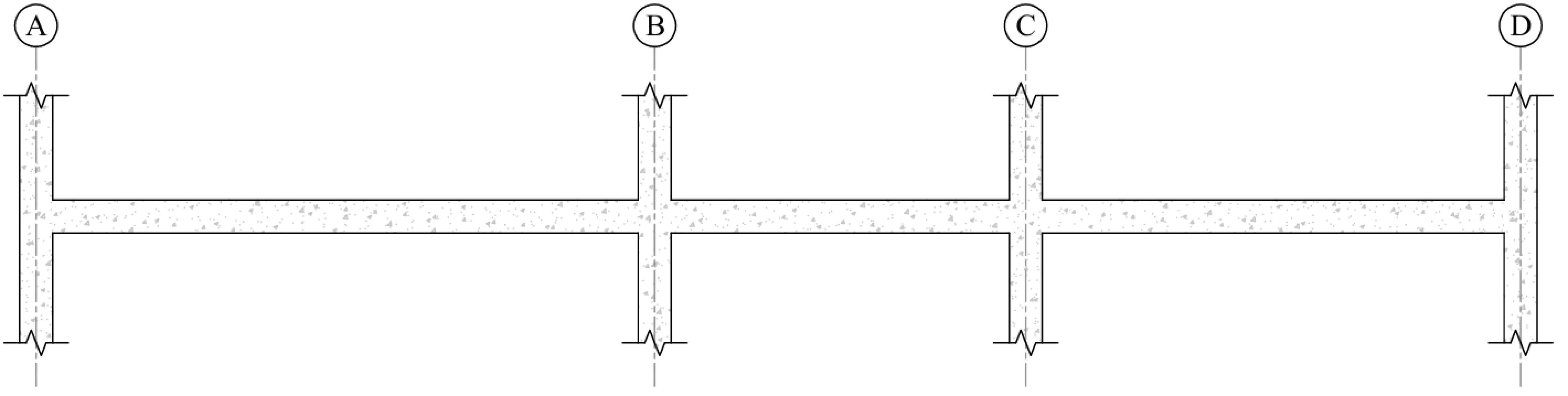
Determine moment distribution factors and fixed-end moments for the frame members. The moment distribution procedure will be used to analyze the frame. Stiffness factors, carry over factors, and fixed-end moment factors for the beams and columns are determined as follows:
Determine the elastic bending moment diagrams for each of the load patterns per ACI and the maximum moment envelope values for all patterns as shown in Table 1.
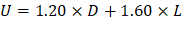
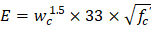
ACI 318-14 (6.4)
| ACI 318-14 (Eq. 5.3.1b) |
| |
| |
|
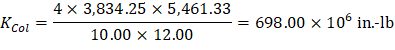
1.2. Flexural Stiffness of Beams and Columns Ends, K
|
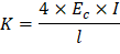
Where K is referred to as stiffness factor at beam or column end and can be defined as the amount of moment required to rotate the end of the beam or column 1 rad.
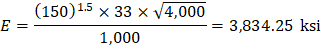
ACI 318-14 (Eq. 19.2.2.1.a)
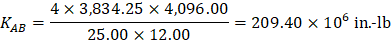
For member AB:

For column Ends:


The distribution factor for a member that is connected to a fixed joint is defined as the fraction of the total resisting moment supplied by this member.
For member AB: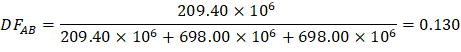
COF = 0.5
Where COF is the Carry-Over Factor that represents the fraction of the moment that is “carried over” from the joint to the beam end when the beam far end is fixed.
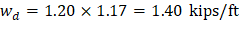
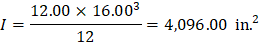
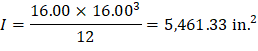
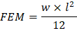
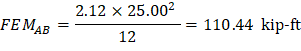
For a beam with uniformly distributed load and fixed ends, FEM can be found using the following equation:
For member AB for Load Pattern I:
1.6. Beam Analysis Using Moment Distribution Method
Repeat the previous steps to all frame members to obtain the parameters necessary for the analysis. Moment distribution for the five loading conditions is shown in Table 1. Counter-clockwise rotational moments acting on member ends are taken as positive. Maximum positive span moments are determined from the following equation:
|
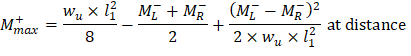
Where:
• Mmax+ | = | Maximum positive moment in the span |
• ML- | = | Negative moment in the left support |
• MR- | = | Negative moment in the right support |
• l1 | = | The span length |
For Load Pattern I:
Maximum positive moment in spans A-B.
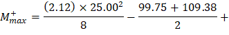
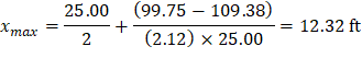
Where:
ML- = 99.75 kip-ft MR- = 109.38 kip-ft
Maximum positive moment in spans B-C.
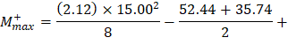
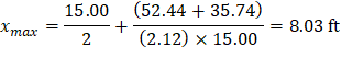
Where:
ML- = 52.44 kip-ft MR- = 35.74 kip-ft
Maximum positive moment in spans C-D.
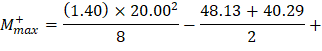
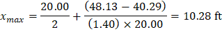
Where:
ML- = 48.13 kip-ft MR- = 40.29 kip-ft
Joint | A | B | C | D | ||
Member | AB | BA | BC | CB | CD | DC |
DF | 0.130 | 0.107 | 0.179 | 0.174 | 0.130 | 0.158 |
COF | 0.500 | 0.500 | 0.500 | 0.500 | 0.500 | 0.500 |
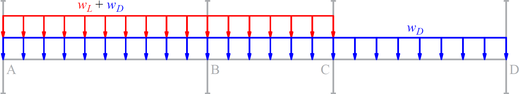
Load Pattern I (S2*) | ||||||
LP I |
| |||||
Joint | A | B | C | D | ||
Member | AB | BA | BC | CB | CD | DC |
FEM | 110.44 | -110.44 | 39.76 | -39.76 | 46.68 | -46.68 |
M- (kip-ft) | 99.75 | -109.38 | 52.44 | -35.74 | 48.13 | -40.29 |
M+ (kip-ft) | 61.13 | 15.84 | 25.86 | |||
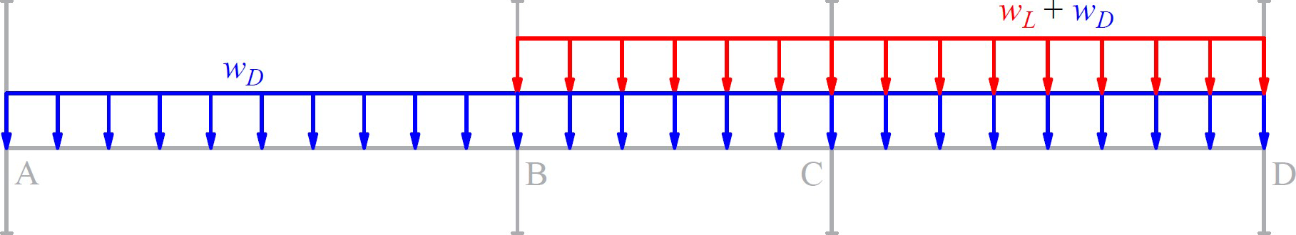
Load Pattern II (Odd*) | ||||||
LP II |
| |||||
Joint | A | B | C | D | ||
Member | AB | BA | BC | CB | CD | DC |
FEM | 110.44 | -110.44 | 26.26 | -26.26 | 70.68 | -70.68 |
Dist. | ||||||
M- (kip-ft) | 100.54 | -107.60 | 38.43 | -27.86 | 68.87 | -62.76 |
M+ (kip-ft) | 61.60 | 6.42 | 40.23 | |||
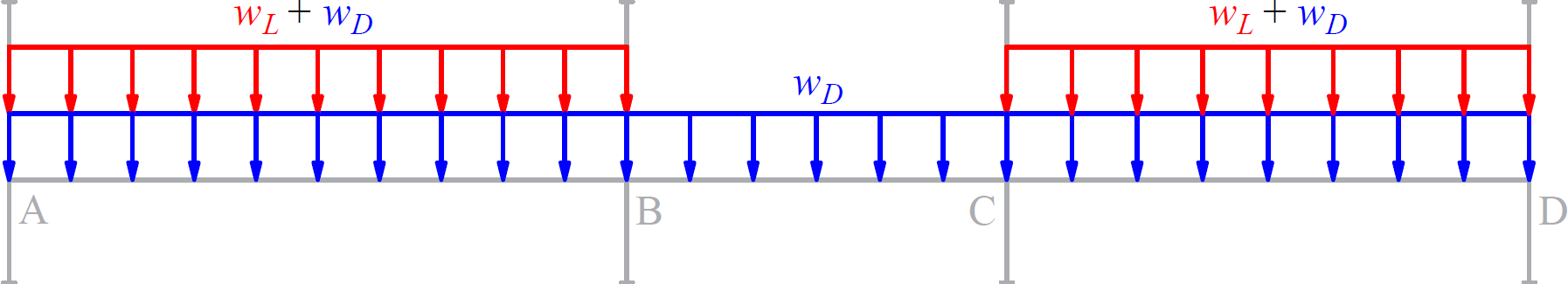
Load Pattern III (S3*) | ||||||
LP III |
| |||||
Joint | A | B | C | D | ||
Member | AB | BA | BC | CB | CD | DC |
FEM | 72.94 | -72.94 | 39.76 | -39.76 | 70.68 | -70.68 |
M- (kip-ft) | 65.36 | -73.38 | 43.67 | -43.07 | 71.20 | -61.74 |
M+ (kip-ft) | 40.07 | 16.26 | 39.60 | |||
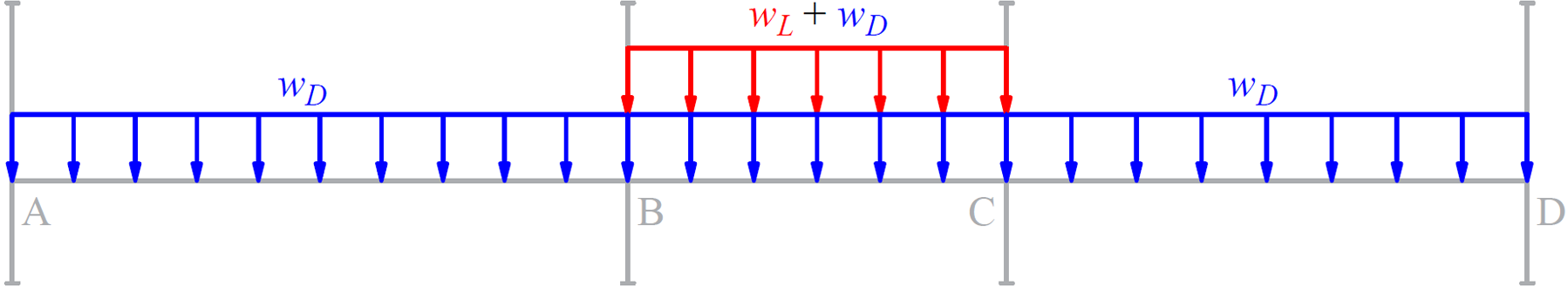
Load Pattern IV (Even*) | ||||||
LP IV |
| |||||
Joint | A | B | C | D | ||
Member | AB | BA | BC | CB | CD | DC |
FEM | 72.94 | -72.94 | 39.76 | -39.76 | 46.68 | -46.68 |
M- (kip-ft) | 65.26 | -73.62 | 45.54 | -38.72 | 48.59 | -40.09 |
M+ (kip-ft) | 40.01 | 17.56 | 25.75 | |||
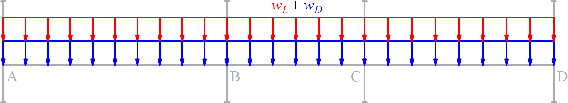
Load Pattern V (All*) | ||||||
LP V |
| |||||
Joint | A | B | C | D | ||
Member | AB | BA | BC | CB | CD | DC |
FEM | 110.44 | -110.44 | 39.76 | -39.76 | 70.68 | -70.68 |
M- (kip-ft) | 99.85 | -109.14 | 50.57 | -40.10 | 70.74 | -61.94 |
M+ (kip-ft) | 61.19 | 14.42 | 39.73 | |||
Envelop of Maximum Moments | ||||||
|
| |||||
Span | AB | BC | CD | |||
ML | MR | ML | MR | ML | MR | |
Max Mu- | 100.54 | -109.38 | 52.44 | -43.07 | 71.20 | -62.76 |
Max Mu- | 83.53 | -91.92 | 41.57 | -32.97 | 57.22 | -49.30 |
Max Mu+ | 61.60 | 17.56 | 40.23 | |||
‡ Moments units are kip-ft * Live load pattern designation in spBeam | ||||||