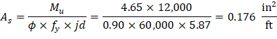
Calculate the required reinforcement to resist the first interior support negative moment:
Mu = 4.65 kips-ft/ft
Use #4 bars with 0.75 in. concrete clear cover per ACI 318-14 (Table 20.6.1.3.1). The distance from extreme compression fiber to the centroid of longitudinal tension reinforcement, d, is calculated below:
To determine the area of steel, assumptions have to be made whether the section is tension or compression controlled, and regarding the distance between the resultant compression and tension forces along the slab section (jd). In this example, tension-controlled section will be assumed so the reduction factor ϕ is equal to 0.9, and jd will be taken equal to 0.978 × d. The assumptions will be verified once the area of steel is finalized.
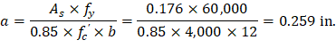
Assume
Unit strip width, b = 12 in.
Recalculate ‘a’ for the actual As = 0.176 in.2 per ft:
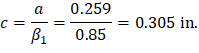

Therefore, the assumption that section is tension-controlled is valid.
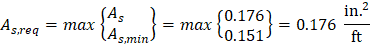
The minimum reinforcement shall not be less than | |
ACI 318-14 (Table 7.6.1.1) | |
| |
For this required steel area, the steel reinforcement ratio is
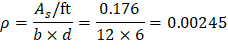
This reinforcement ratio is notably low, typical for many slabs. Hence, it's evident that the selected slab thickness is adequate for the design bending moments.
Provide No. 4 bars at 12 in. | |
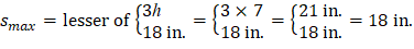
The maximum allowed spacing (smax): | |
| ACI 318-14 (7.7.2.3) |
Thus, s = 12 in. < smax = 18 in. |
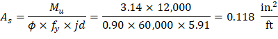
Calculate the required reinforcement to resist the exterior span positive moment:
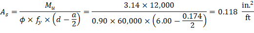
Mu = 3.14 kips-ft/ft
The distance from extreme compression fiber to the centroid of longitudinal tension reinforcement:
d = 6.00 in.
To determine the area of steel, assumptions have to be made whether the section is tension or compression controlled, and regarding the distance between the resultant compression and tension forces along the slab section (jd). In this example, tension-controlled section will be assumed so the reduction factor ϕ is equal to 0.9, and jd will be taken equal to 0.986 × d. The assumptions will be verified once the area of steel is finalized.
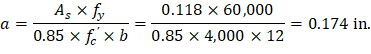
Assume
Unit strip width, b = 12 in.
Recalculate ‘a’ for the actual As = 0.118 in.2 per ft:
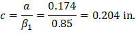

Therefore, the assumption that section is tension-controlled is valid.
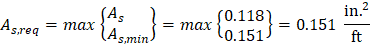
The minimum reinforcement shall not be less than | |
ACI 318-14 (Table 7.6.1.1) | |
| |
Provide No. 4 bars at 12 in. | |
The maximum allowed spacing (smax): | |
| ACI 318-14 (7.7.2.3) |
Thus, s = 12 in. < smax = 18 in. | |

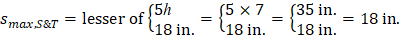
Check the shrinkage and temperature reinforcement (As,S&T) requirement:
| ACI 318-14 (Table 7.6.1.1) |
| ACI 318-14 (7.7.2.4) |
Thus, use s = 15 in. < smax,S&T = 18 in. | |
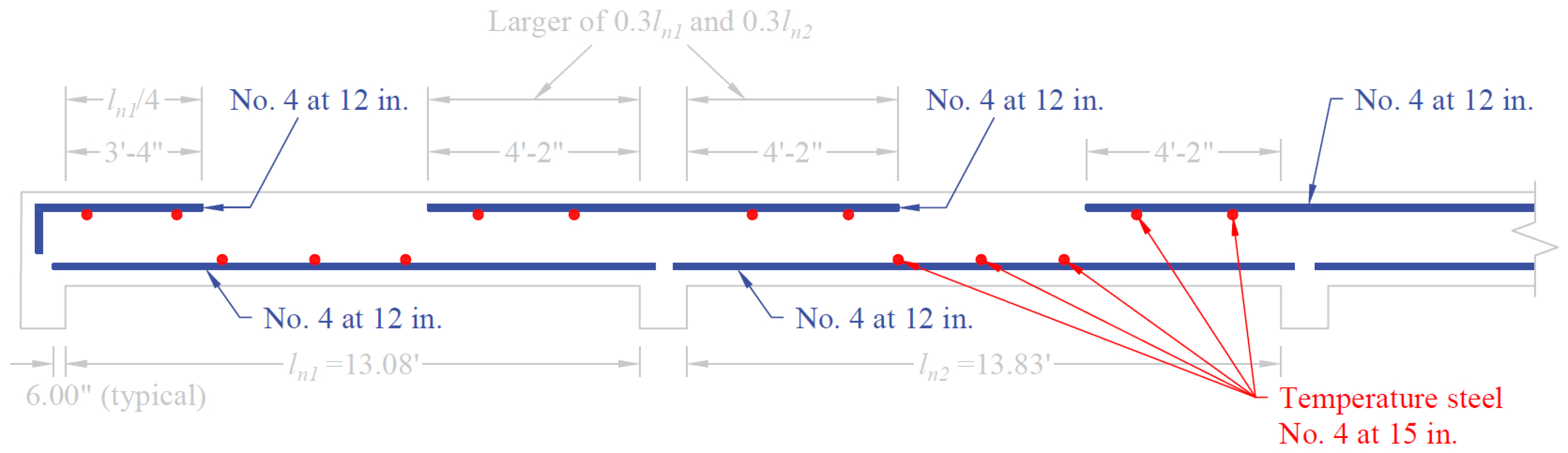
Therefore, provide No. 4 bars at 15 in. o.c., as shrinkage and temperature reinforcement. | |
| |


Using the equation above, this results in a steel area equal to 0.160 in.2/ft. These bars can be placed either in the top or bottom of the slab. If they are placed at the top, they should be placed below the top flexural reinforcement to permit the larger effective depth for that flexural reinforcement, and similarly, they should be placed on top of the bottom layer of flexural reinforcement, as shown in Figure 3.
Check reinforcement spacing for crack control:
The maximum spacing of the flexural reinforcement closest to the tension face of the slab shall be:
| ACI 318-14 (Table 24.3.2) | ||
ACI 318-14 (24.3.2.1) | |||
cc | = | 0.75 in. | |
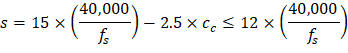
Thus,
At supports and mid-span
Thus, maximum bar spacing is 12 in.
Based on the procedure outlined above, values for all span locations are given in the following table.
Table 3 - One-Way Slab Flexural Design Summary | |||||
External Support | Exterior Midspan | First Interior Support | Interior Midspan | Second Interior Support | |
Mu (kips-ft/ft) | 1.83 | 3.14 | 4.65 | 3.07 | 4.47 |
As,req’d (in.2) | 0.068 | 0.118 | 0.176 | 0.115 | 0.169 |
As,min (in.2) | 0.151 | 0.151 | 0.151 | 0.151 | 0.151 |
Select bars | No. 4 at 12 in. | No. 4 at 12 in. | No. 4 at 12 in. | No. 4 at 12 in. | No. 4 at 12 in. |
As,provided (in.2) | 0.200 | 0.200 | 0.200 | 0.200 | 0.200 |
The reference provides standard bar cutoff points for one-way slabs that satisfy the limitations on span lengths and loadings in ACI 318-14 (Table 6.5.2). These values are shown in the following Figure.
Wight 7th (8-8 and Fig. A-5c)