11. Observations & Discussions
11.1. Modeling End Supports Conditions
In continuous one-way concrete slabs, the moment values along the exterior spans vary based on the rotational resistance offered by the exterior support. Engineers typically encounter two common exterior support conditions:
1. Unrestrained exterior support: In this condition, the exterior support is not built integrally with the slab and thus offers no resistance to rotations at the slab end. The support provides bearing resistance to carry the vertical loads and is considered a pin support. When employing spBeam to model a continuous one-way slab, this condition is the default setting when utilizing an exterior pin support, with the rotational stiffness (Kry) is set to zero by default.
2. Integral exterior support: In this condition, the exterior support is built integrally with the slab and thus offers resistance to rotations at the slab end. The support provides bearing resistance along moment resistance and is considered a semi-rigid connection. When employing spBeam to model a continuous one-way slab, rotational stiffness can be used to simulate this end support condition. For this example, the end support is a spandrel girder integral to the external span end, the ACI code approximates the moment at spandrel girder end support to be (wu × ln2)/24 (ACI 318-14 (Table 6.5.2)). This can be used as one method to estimate the rotational stiffness of the spandrel girder by trial and error.
11.2. Modeling Transverse Beams
In spBeam the user can incorporate the physical dimensions of the transverse beams/girders to incorporate the added stiffness provided at the support locations. This takes advantage of any additional beam stiffness derived from increased depth and reduces the length of the span segment attributed to just the slab thickness. Modeling these additional support details produces a model with closer representation of the design conditions and potentially removes some conservatism. Engineering judgment is required to determine whether to include transverse beams/girders in the one-way slab modeling as it increases the parameters involved in determining both analysis and design results. The following figure shows the effect of modeling the transverse beams on the design moment values as compared with a simple pin support at the support center.
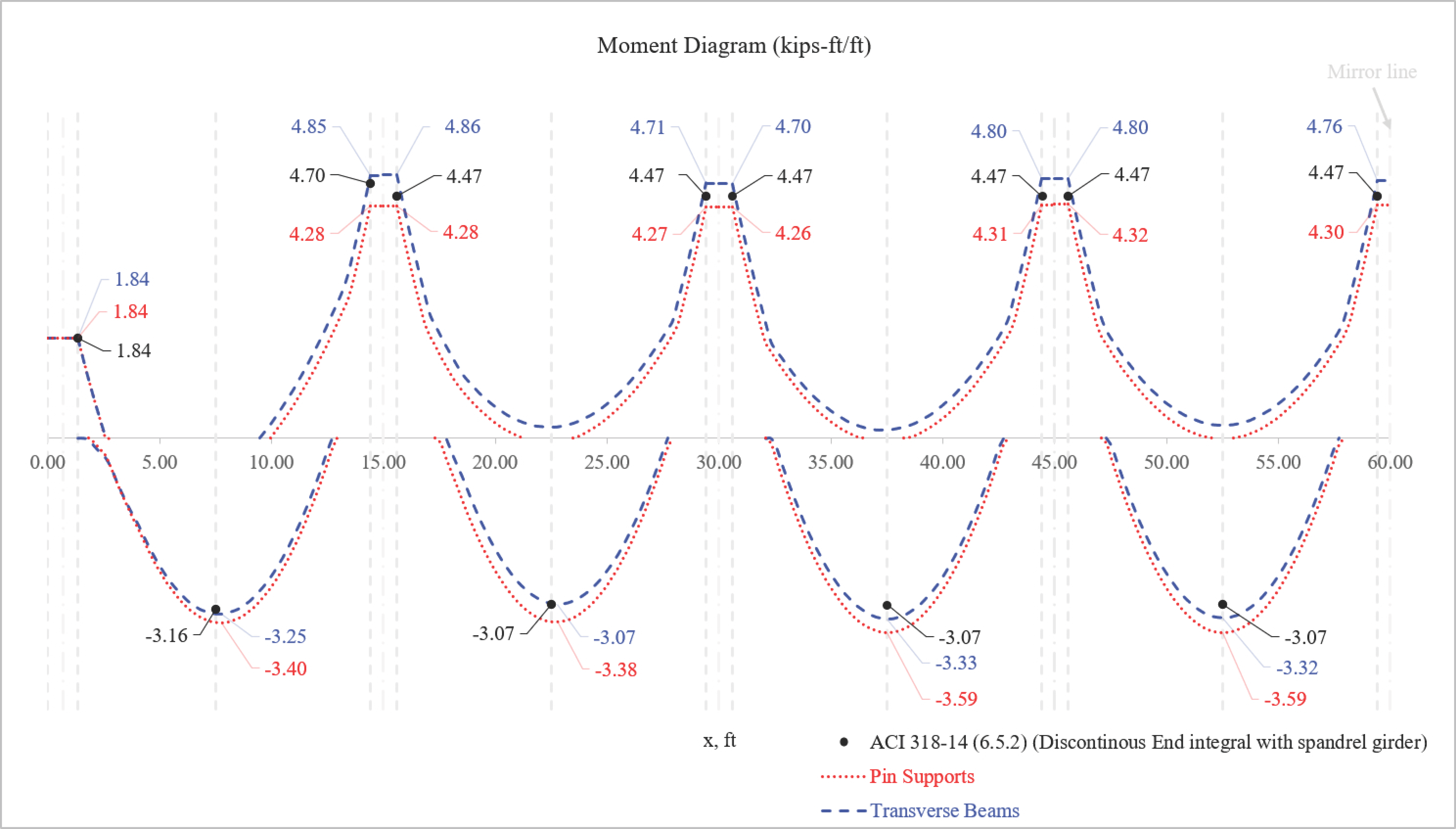
Figure 4 – Moment Diagram Comparison
11.3. One-Way (Beam Action) Shear Critical Section
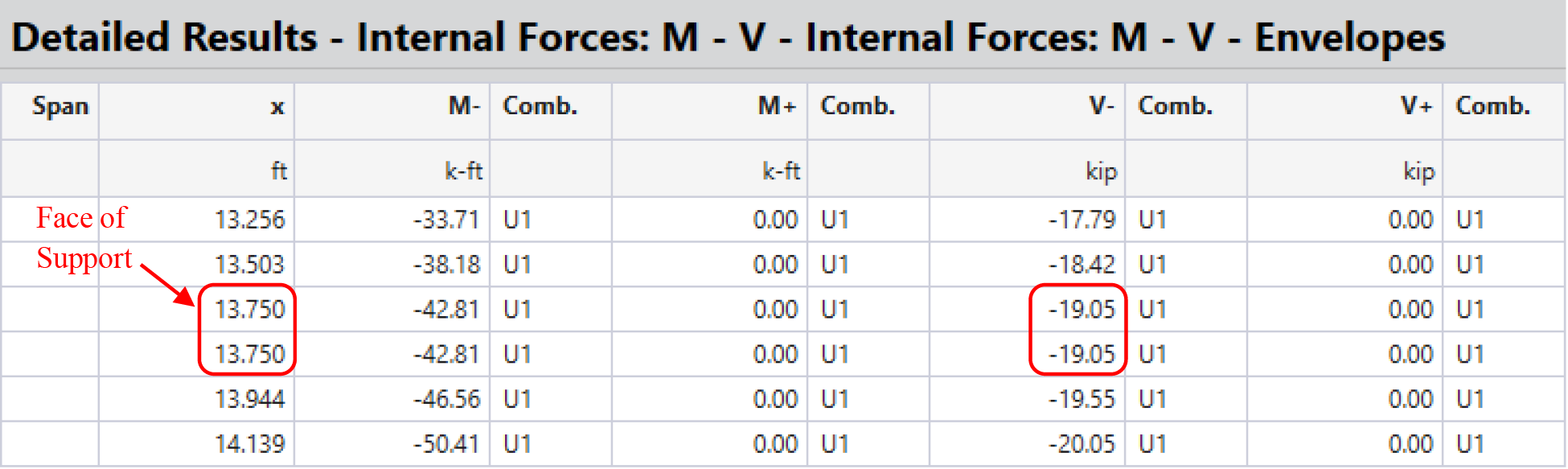
Using the ACI shear coefficients, the one-way shear is calculated and checked at face of support for simplicity. When using spBeam, the one -way (beam action) shear is checked at a critical section (d away from support face) as permitted by ACI 318-14 (7.4.3.2) (Figure 5). Nevertheless, the shear force at any location along the span (including the support face) can be acquired from the “Internal Forces: M-V-Envelopes” section under “Detailed Results” as required by the user (Figure 6).
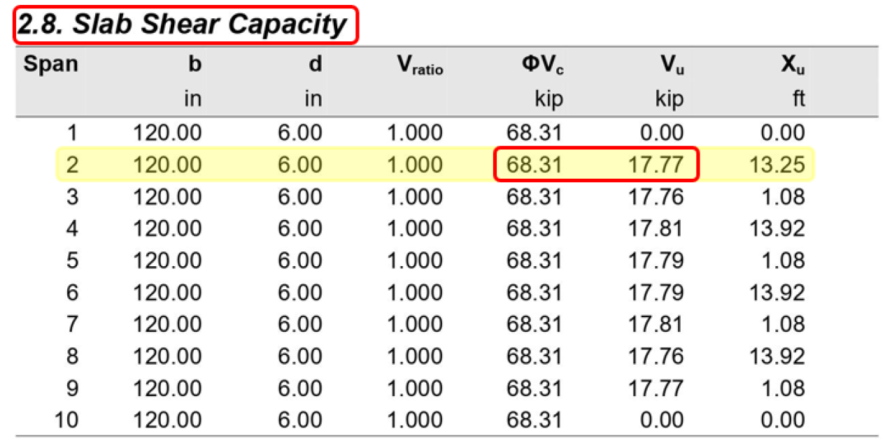
Figure 5 – Slab Shear Capacity (spBeam)