5. Moment Magnification along Length of Compression Member
In sway frames, if an individual compression member has: | |
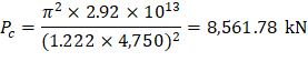
| CSA A23.3-19 (Eq. 10.26) |
It shall be designed for the factored axial load, Pf and moment, Mc, computed using Clause 10.15.3 (Nonsway frame procedure), in which M1 and M2 are computed in accordance with Clause 10.16.2. | |
CSA A23.3-19 (10.16.4) | |
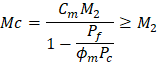
| CSA A23.3-19 (10.15.3.1) |
Where: | |
| CSA A23.3-19 (10.15.3.2) |
M2 = the second-order factored moment (magnified sway moment) | |
And, the member resistance factor would be ϕm = 0.75 | CSA A23.3-19 (10.15.3.1) |
| CSA A23.3-19 (Eq. 10.18) |
Where: | |
| CSA A23.3-19 (10.15.3.1) |
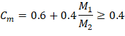
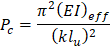
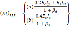
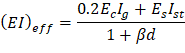
There are two options for calculating the flexural stiffness of slender concrete columns (EI)eff. The first equation provides accurate representation of the reinforcement in the section and will be used in this example and is also used by the solver in spColumn.
Further comparison of the available options is provided in “Effective Flexural Stiffness for Critical Buckling Load of Concrete Columns” technical note.
5.1. Gravity Load Combination #2 (Gravity Loads Only)
| CSA A23.3-19 (10.14.2) |
| |
| CSA A23.3-19 (Eq. 10.26) |
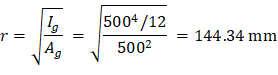
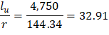
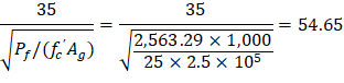
Since 32.91 < 54.65, calculating the moments along the column length is not required. | |
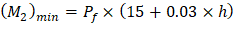
Check minimum moment: | CSA A23.3-19 (10.15.3.1) |
CSA A23.3-19 does not require to design columns in sway frames for a minimum moment. However, the reference decided conservatively to design the column for the larger of computed moments and the minimum value of M2. | |
| CSA A23.3-19 (3.2) |
| |

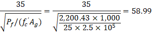
5.2. Lateral Load Combination #7 (Gravity Plus Wind Loads)
| CSA A23.3-19 (Eq. 10.26) |
Since 32.91 < 58.99, calculating the moments along the column length is not required. | |
Check minimum moment: | CSA A23.3-19 (10.15.3.1) |
CSA A23.3-19 does not require to design columns in sway frames for a minimum moment. However, the reference decided conservatively to design the column for the larger of computed moments and the minimum value of M2. | |
| CSA A23.3-19 (3.2) |
| |


Mc1 and Mc2 will be considered separately to ensure proper comparison of resulting magnified moments against negative and positive moment capacities of unsymmetrical sections as can be seen in the following figure.

Figure 5 - Column Interaction Diagram for Unsymmetrical Section
A summary of the moment magnification factors and magnified moments for the exterior column for all load combinations using equation CSA A23.3 (Eq. 10.24) to calculate δs is provided in the table below for illustration.
Table 5 - Factored Axial loads and Magnified Moments along Exterior Column Length | |||||
No. | Load Combination | Axial Load, kN | Using CSA Eq. 10.24 | ||
δ | Mc1, kN-m | Mc2, kN-m | |||
1 | 1.4D | 2,261.28 | 1 | 150.30 | 165.20 |
2 | 1.25D + 1.5L | 2,563.29 | 1 | 235.35 | 256.79 |
3 | 1.25D + 1.5L + 0.4W | 2,563.29 | 1 | 282.89 | 312.32 |
4 | 1.25D + 1.5L - 0.4W | 2,563.29 | 1 | 187.80 | 201.26 |
5 | 0.9D + 1.5L + 0.4W | 1,997.97 | 1 | 242.28 | 267.47 |
6 | 0.9D + 1.5L - 0.4W | 1,997.97 | 1 | 153.26 | 163.51 |
7 | 1.25D + 0.5L + 1.4W | 2,200.43 | 1 | 326.53 | 369.17 |
8 | 1.25D + 0.5L - 1.4W | 2,200.43 | 1 | -1.31 | 9.30 |
9 | 0.9D + 0.5L + 1.4W | 1,635.11 | 1 | 279.25 | 316.54 |
10 | 0.9D + 0.5L - 1.4W | 1,635.11 | 1 | -18.57 | -31.28 |
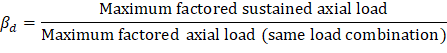
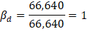
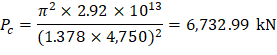
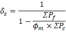
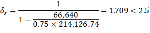
For column design, CSA A23.3 requires that δs to be computed from Clause 10.16.3.2 using ∑Pf and ∑Pc under gravity load shall be positive and shall not exceed 2.5. βd shall be taken as the ratio of the maximum factored sustained axial load to the maximum factored axial load associated with the same load combination. For values of δs above the limit, the frame would be very susceptible to variations in EI, foundation rotations and the like. If this value exceeds 2.5, the frame must be stiffened to reduce δs.
CSA A23.3-19 (10.16.5)
| CSA A23.3-19 (10.16.5) |
| |
| CSA A23.3-19 (Eq. 10.18) |
Where: | |
| CSA A23.3-19 (Eq. 10.19) |
| |
For exterior columns with two beams framing into them in the direction of analysis: | |
| |
For interior columns and exterior columns with two beams framing into them in the direction of analysis: | |
| |
| |
Where the member resistance factor is ϕm = 0.75 | CSA A23.3-19 (10.15.3.1) |
| CSA A23.3-19 (Eq. 10.24) |
| |
Thus, the frame is stable. | |