4. Required Area of Longitudinal Reinforcement for Flexure and Axial Forces
ACI 318-19 (18.10.5)
The design strength interaction diagram for this wall is given in the figure below. Detailed discussion about generating interaction diagrams for shear walls can be found in “Interaction Diagram - Barbell Concrete Shear Wall Unsymmetrical Boundary Elements (ACI 318-19)” Design Example. The longitudinal reinforcement selected by the reference consists of 44-#8 bars in each flange and 2-#8 bars spaced at 10.0 in. on center in the web. 4-#8 bars are required at the mid-depth of the flange (two bars each end) in order to satisfy the maximum spacing requirement in ACI 318-19 (18.10.6.4(f)) for bars around the perimeter of the special boundary element (the maximum spacing is the lesser of 14 in. and two-thirds the boundary element thickness, which is equal to 16.0 in.; see Special Boundary Elements - Compressive Approach and Special boundary element required transverse reinforcement below). All load combinations fall within the boundary of the design strength interaction diagram.
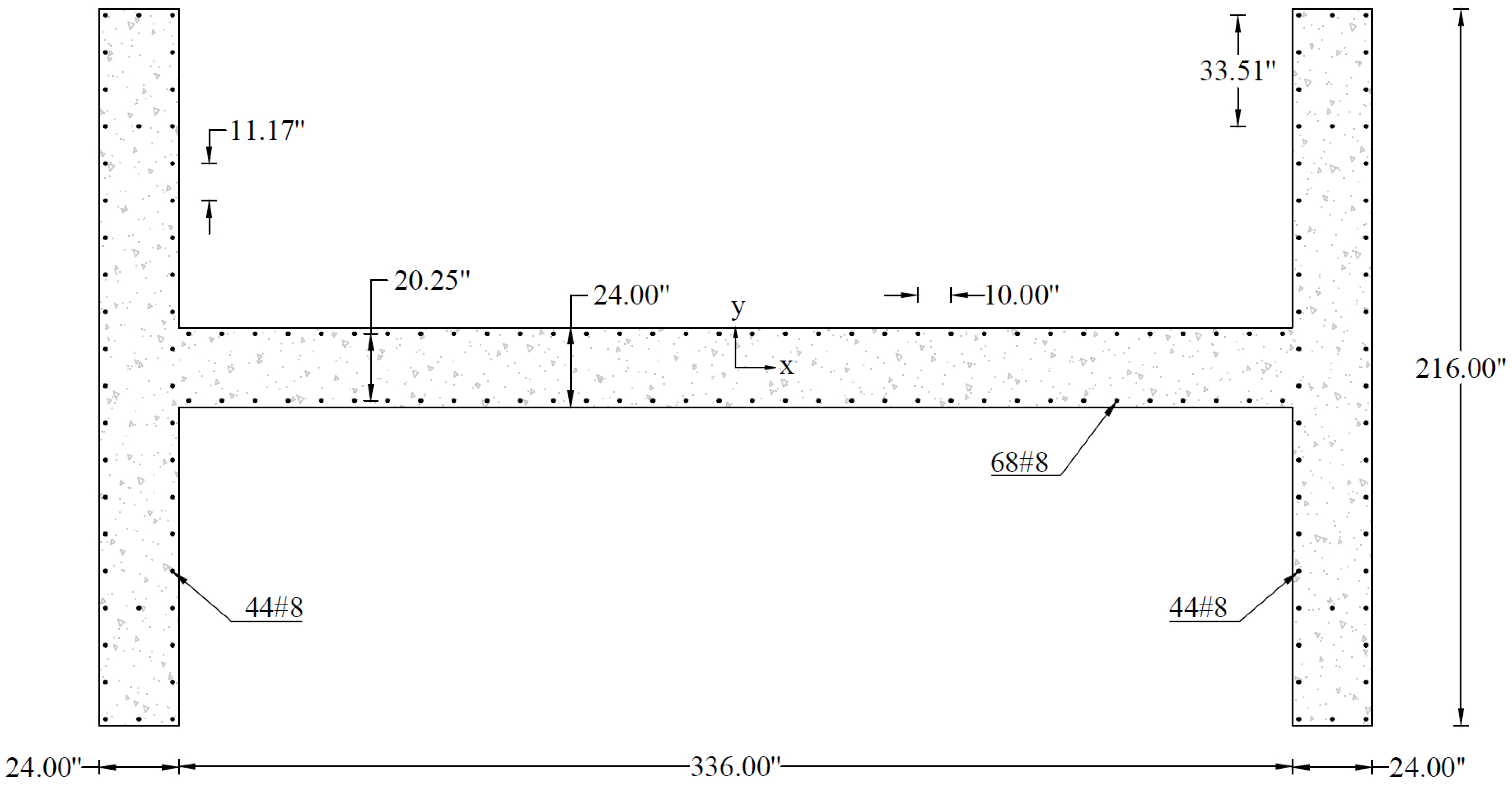
Figure 2 - Reinforced Concrete Wall Cross-Section
Table 3 - Factored Loads and Moments with Corresponding Capacities | |||||
No. | Load Combination | Pu, kip | Mu, ft-kip | ϕPn, kip | ϕMn, ft-kip |
1 | 1.4D | 22,072.5 | 0.0 | 22,072.5 | 458,616.69 |
2 | 1.2D + 1.6L + 0.5Lr | 26,293.9 | 0.0 | 26,293.9 | 504,114.69 |
3 | 1.2D + 0.5L + 1.6Lr | 21,291.9 | 0.0 | 21,291.9 | 448,922.66 |
4 | 1.3D + 0.5L + 1.3Qe | 22,793.1 | 212,941.3 | 22,793.1 | 467,210.25 |
5 | 0.8D + 1.3Qe | 12,612.9 | 212,941.3 | 12,612.9 | 327,498.25 |
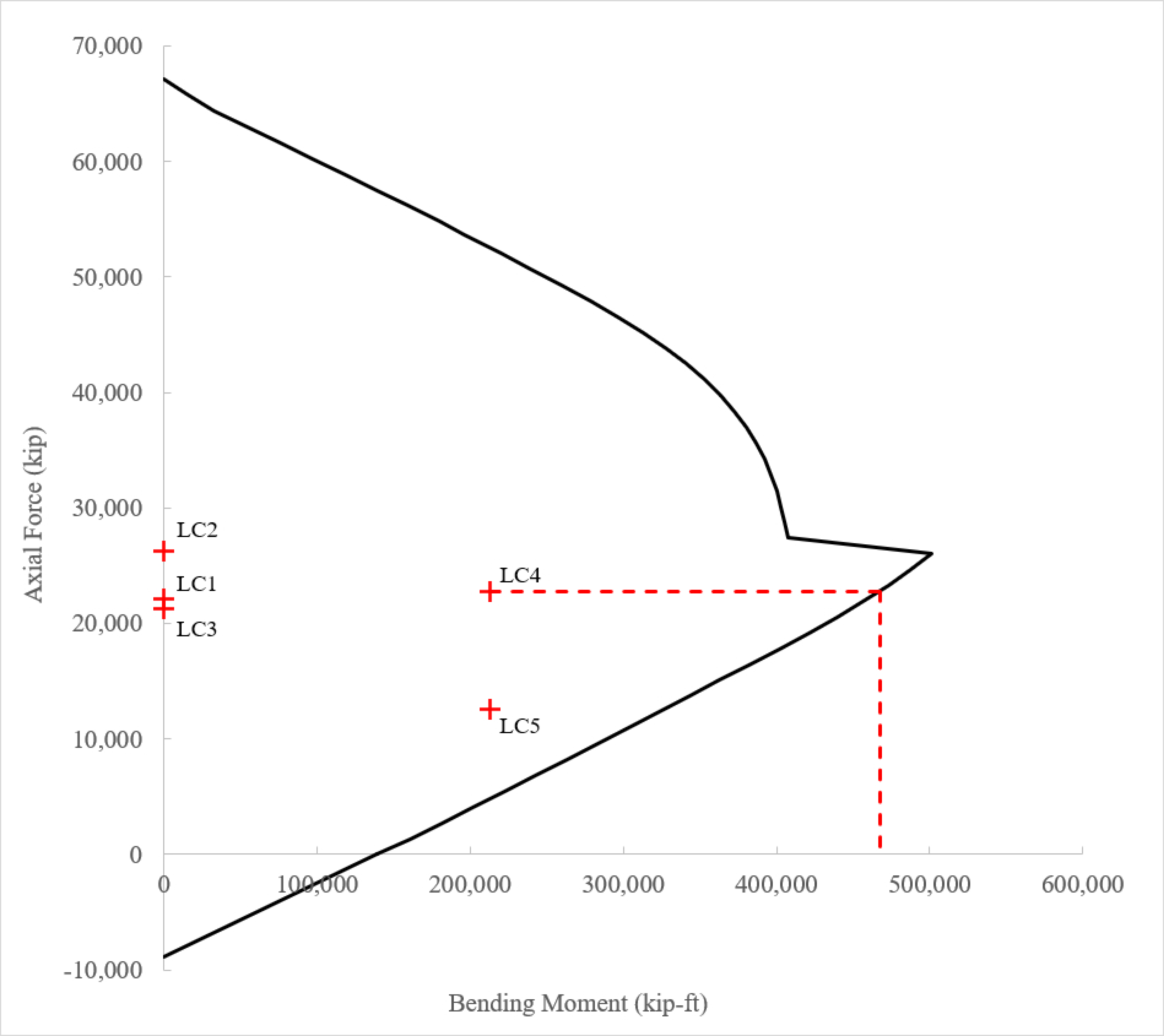
Figure 3 - Design Strength Interaction Diagram
Walls or wall piers with that are effectively continuous from the base of structure to top of wall and are designed to have a single critical section for flexure and axial loads shall have longitudinal reinforcement at the ends of a vertical wall segment that satisfies (a) through (c). | |
a) Longitudinal reinforcement ratio within 0.15lw from the end of a vertical wall segment, and over a width equal to the wall thickness, shall be at least | |
b) The longitudinal reinforcement required by (a) shall extend vertically above and below the critical section at least the greater of lw and Mu / 3Vu. | |
c) No more than 50 percent of the reinforcement required by (a) shall be terminated at any one section. | |
ACI 318-19 (18.10.2.4) | |
Check the minimum longitudinal reinforcement requirements of ACI 318-19 (18.10.2.4(a)) (see Figure 5).
| ACI 318-19 (Fig. 18.10.2.4) |
There are 7-#8 bars within the 2.7-ft width at each end of both flanges; therefore, | |
| ACI 318-19 (18.10.2.4(a)) |
There are 6-#8 bars within the 2.7-ft width in the web; therefore, | |
| ACI 318-19 (18.10.2.4(a)) |
Therefore, the requirements of ACI 18.10.2.4(a) are satisfied. | |
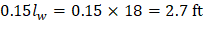
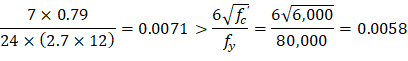
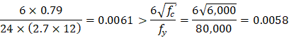
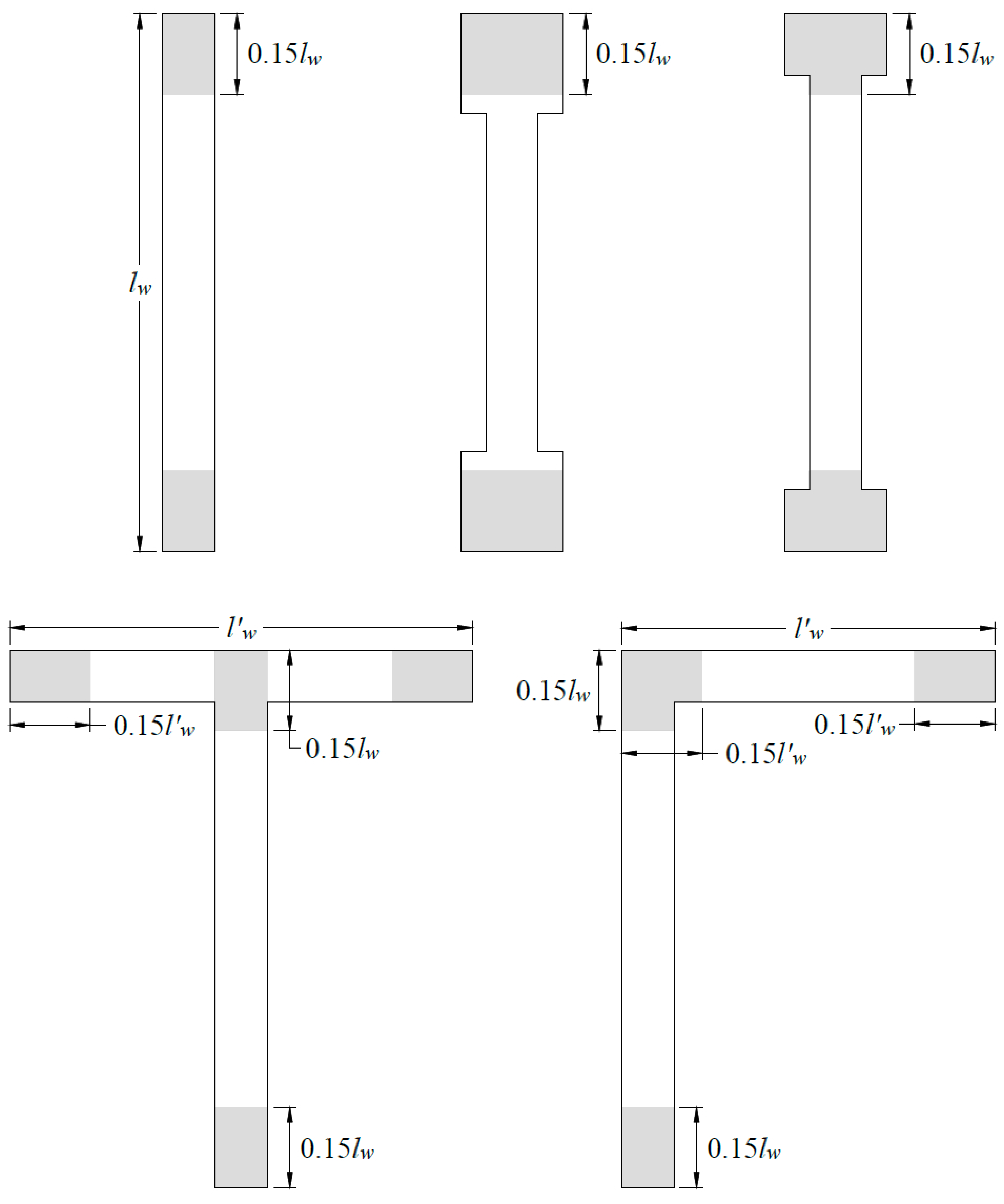
Figure 4 - Locations of longitudinal reinforcement required by ACI 318-19 (18.10.2.4(a)) in different configurations of wall sections
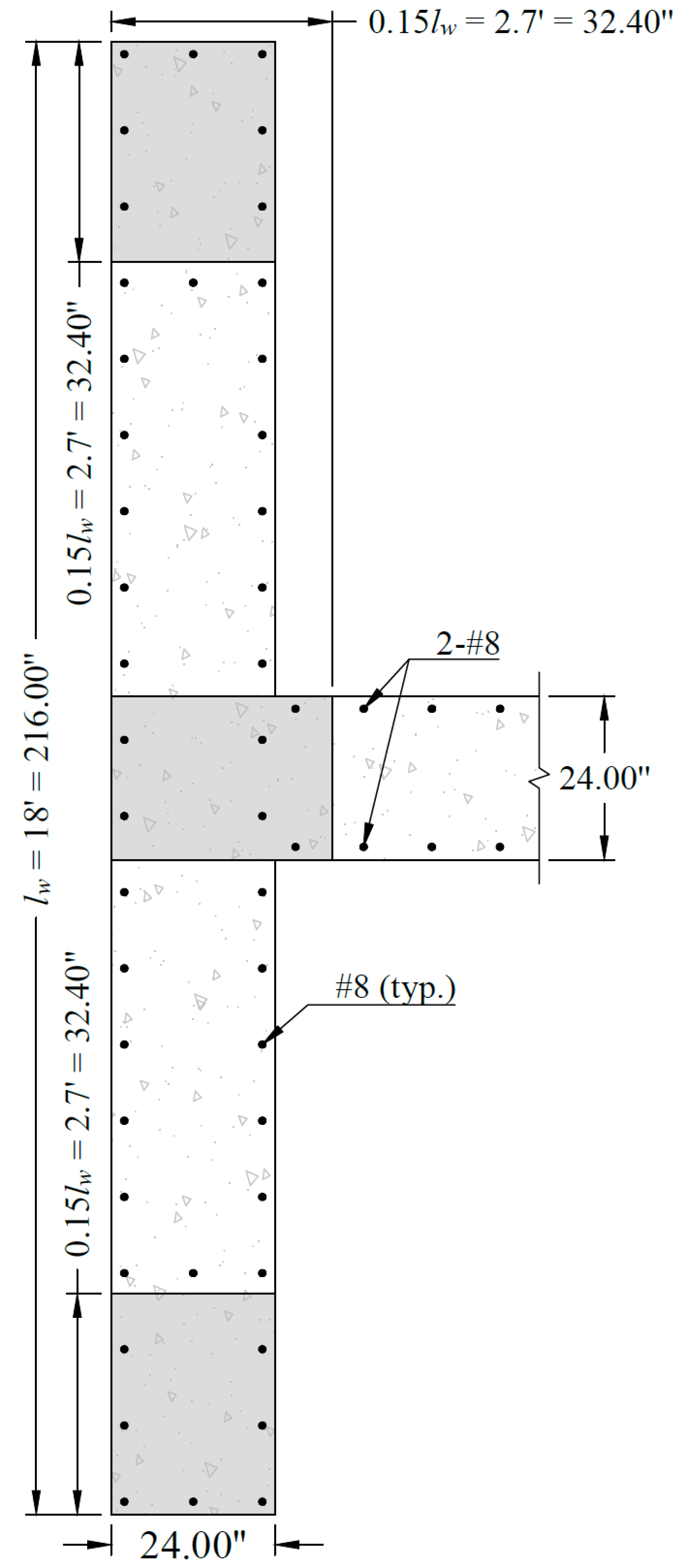
Figure 5 - Minimum longitudinal reinforcement in accordance with ACI 318-19 (18.10.2.4)