16. Conclusions & Observations
ACI 318 allows two approaches to evaluate the need for special boundary elements to confine the concrete and restrain the longitudinal reinforcement in walls so buckling of the reinforcing bars doesn’t occur: | |
1) Displacement-Based Approach | ACI 318-19 (18.10.6.2) |
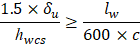
In this approach, special transverse reinforcement is provided in special structural walls compression zones where the strain at the extreme compression fiber exceeds a critical value when the wall is subjected to 1.5 times the design displacement which occurs at the top of the wall. Special boundary elements are required when: | |
| ACI 318-19 (18.10.6.2(a)) |
2) Compressive Stress Approach | ACI 318-19 (18.10.3.1) |
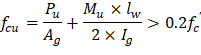
In this approach, special transverse reinforcement is provided in special structural walls compression zones where: | |
| ACI 318-19 (18.10.6.3) |
The special boundary elements may be discontinued where the combined stress is less than 0.15fc’. | |
In this example, the Compressive Stress Approach is used to determine the need for special boundary elements. The Displacement-Based Approach will be used in future examples. | |
ACI 318 distinguishes between ordinary and special reinforced concrete structural walls in the calculation of design shear forces and nominal shear strengths. For special structural walls, ACI 318 requires that the design shear forces obtained from lateral load analysis be amplified with appropriate load factors to account for flexural overstrength at critical sections where yielding of longitudinal reinforcement is expected, and dynamic amplification due to higher mode effects. The approach used to determine the amplified shear forces is similar to that used in New Zealand Standard 3101 (2006). | |
ACI 318-19 (R18.10.3.1) | |
The nominal shear strength of special structural walls is given by ACI 318 (18.10.4.1). This equation recognizes the higher shear strength of walls with high shear-to-moment ratios. The nominal shear strength is given in terms of the gross area of the section resisting shear. For a rectangular section without openings, that term refers to the gross area of the cross section rather than to the product of the width and the effective depth. | |
ACI 318-19 (R18.10.4) | |
ACI 318 indicates that the flexural strength of special structural (shear) walls is determined according to procedures commonly used for columns based on a strain compatibility analysis (Section 22.4 Axial Strength or Combined Flexural and Axial Strength). The generation of a design strength interaction diagram (or nominal interaction diagram for Mpr calculations) for these walls could be challenging and cumbersome due to the complexity of section geometry and/or reinforcement configurations and the use of a computer aid can save time and eliminate errors. StucturePoint’s spColumn program can, quickly, simply, and accurately generate the interaction diagram for all commonly encountered structural wall (shear and core walls) sections regardless of their complexity.
The reference mentioned that the wall covered in this example is part of the Seismic Force Resisting System (SFRS) for earthquake loads in the north-south direction. Because the axial force due to seismic forces acting along either of the principal plan axes is negligible, orthogonal load effects in accordance with ASCE/SEI need not be considered. Thus, the wall provided reinforcement must satisfy the effects from axial forces, bending moments, and shear forces in both orthogonal directions independently. spColumn allows user to generate the interaction diagram about either the X- or Y-Axes in Uniaxial bending run mode, and 3D failure surface accounting for the biaxial bending in two directions simultaneously. The added flexibility in the run options allow the user to perform a comprehensive analysis and design of special structural (shear) walls quickly, simply, and accurately by reducing time consumed and minimizing errors.