2. Two-Way Slab Analysis and Design - Using Equivalent Frame Method (EFM)
ACI 318 states that a slab system shall be designed by any procedure satisfying equilibrium and geometric compatibility, provided that strength and serviceability criteria are satisfied. Distinction of two-systems from one-way systems is given by ACI 318-14 (R8.10.2.3 & R8.3.1.2).
ACI 318 permits the use of Direct Design Method (DDM) and Equivalent Frame Method (EFM) for the gravity load analysis of orthogonal frames and is applicable to flat plates, flat slabs, and slabs with beams. The following sections outline the solution per EFM and spSlab software. The solution per DDM can be found in the “Two-Way Flat Plate Concrete Floor System Analysis and Design (ACI 318-14)” example.
EFM is the most comprehensive and detailed procedure provided by the ACI 318 for the analysis and design of two-way slab systems where the structure is modeled by a series of equivalent frames (interior and exterior) on column lines taken longitudinally and transversely through the building.
The equivalent frame consists of three parts:
1) Horizontal slab-beam strip, including any beams spanning in the direction of the frame. Different values of moment of inertia along the axis of slab-beams should be taken into account where the gross moment of inertia at any cross section outside of joints or column capitals shall be taken, and the moment of inertia of the slab-beam at the face of the column, bracket or capital divide by the quantity (1-c2/l2)2 shall be assumed for the calculation of the moment of inertia of slab-beams from the center of the column to the face of the column, bracket or capital.
ACI 318-14 (8.11.3)
2) Columns or other vertical supporting members, extending above and below the slab. Different values of moment of inertia along the axis of columns should be taken into account where the moment of inertia of columns from top and bottom of the slab-beam at a joint shall be assumed to be infinite, and the gross cross section of the concrete is permitted to be used to determine the moment of inertia of columns at any cross section outside of joints or column capitals.
ACI 318-14 (8.11.4)
3) Elements of the structure (Torsional members) that provide moment transfer between the horizontal and vertical members. These elements shall be assumed to have a constant cross section throughout their length consisting of the greatest of the following: (1) portion of slab having a width equal to that of the column, bracket, or capital in the direction of the span for which moments are being determined, (2) portion of slab specified in (1) plus that part of the transverse beam above and below the slab for monolithic or fully composite construction, (3) the transverse beam includes that portion of slab on each side of the beam extending a distance equal to the projection of the beam above or below the slab, whichever is greater, but not greater than four times the slab thickness.
2.1. Equivalent Frame Method (EFM)
In EFM, live load shall be arranged in accordance with 6.4.3 which requires slab systems to be analyzed and designed for the most demanding set of forces established by investigating the effects of live load placed in various critical patterns.
ACI 318-14 (8.11.1.2 & 6.4.3)
Complete analysis must include representative interior and exterior equivalent frames in both the longitudinal and transverse directions of the floor.
ACI 318-14 (8.11.2.1)
Panels shall be rectangular, with a ratio of longer to shorter panel dimensions, measured center-to-center of supports, not to exceed 2.
ACI 318-14 (8.10.2.3)
2.2. Frame Members of Equivalent Frame
Determine moment distribution factors and fixed-end moments for the equivalent frame members. The moment distribution procedure will be used to analyze the equivalent frame. Stiffness factors k, carry over factors COF, and fixed-end moment factors FEM for the slab-beams and column members are determined using the design aids tables at Appendix 20A of PCA Notes on ACI 318-11. These calculations are shown below.
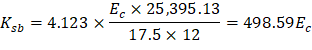
a) Flexural stiffness of slab-beams at both ends, Ksb.
| |
For cF1 = cF2, stiffness factors, kNF = kFN = 4.123 | PCA Notes on ACI 318-11 (Table A1) |
Thus, | PCA Notes on ACI 318-11 (Table A1) |
Where Isb is the moment of inertia of slab-beam section shown in Figure 6 and can be computed as follows:
|
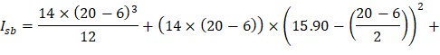
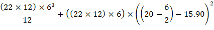
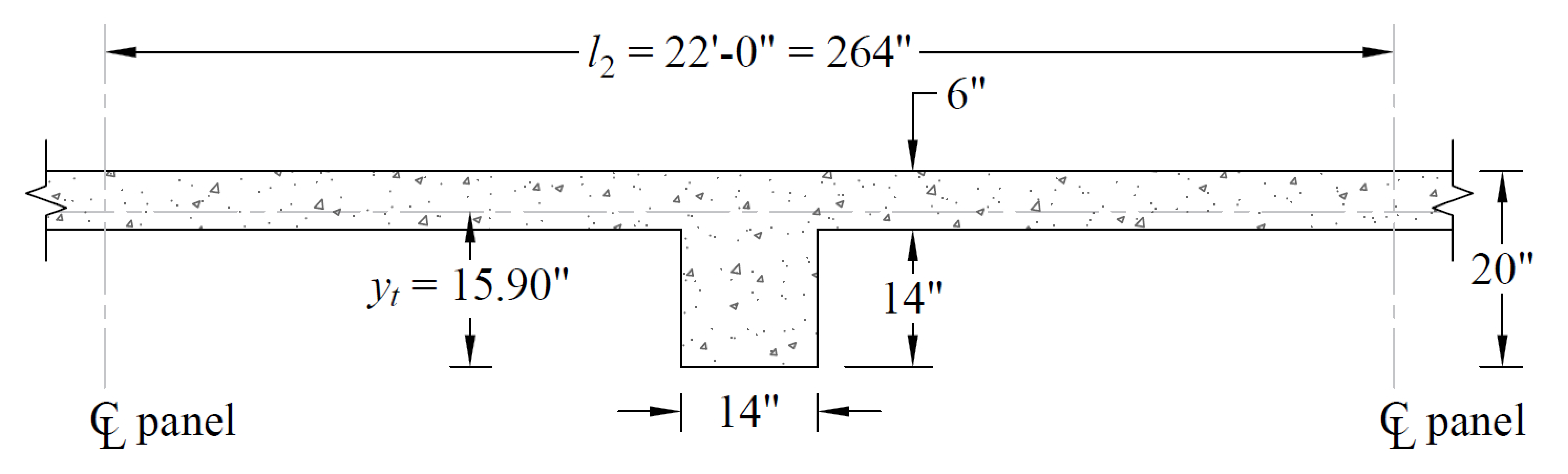
Figure 6 – Cross-Section of Slab-Beam
| |
Carry-over factor COF = 0.507 | PCA Notes on ACI 318-11 (Table A1) |
Fixed-end moment | PCA Notes on ACI 318-11 (Table A1) |
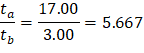
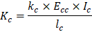
b) Flexural stiffness of column members at both ends, Kc
Referring to Table A7, Appendix 20A,
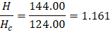
For Interior Columns:
ta = 20 + 6/2 = 17.00 in. | tb = 6/2 = 3.00 in. |
H = 12 ft = 144.00 in. | Hc = H - ta - tb = 144.00 – 17.00 – 3.00 = 124.00 in. |
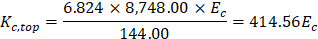
|
|
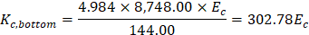
Thus, kc,top = 6.824, kc,bottom = 4.984, COFtop = 0.513 and COFbottom = 0.700 by interpolation.
| PCA Notes on ACI 318-11 (Table A7) |
| |
| |
Where | |
lc = 12 ft = 144.00 in. |

For Exterior Columns:
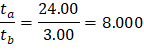
ta = 27 + 6/2 = 24.00 in. | tb = 6/2 = 3.00 in. |
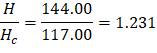
H = 12 ft = 144.00 in. | Hc = H - ta - tb = 144.00 – 24.00 – 3.00 = 117.00 in. |
|
|
Thus, kc,top = 8.589, kc,bottom = 5.293, COFtop = 0.494 and COFbottom = 0.802 by interpolation.
| PCA Notes on ACI 318-11 (Table A7) |
| |
| |
Where | |
lc = 12 ft = 144.00 in. |
c) Torsional stiffness of torsional members, Kt.
| ACI 318-14 (R.8.11.5) |
For Interior Columns: | |
| |
Where: | |
| |
| ACI 318-14 (Eq. 8.10.5.2b) |
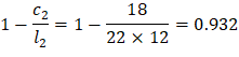

x1 = 14 in. x2 = 6 in. x1 = 14 in. x2 = 6 in. y1 = 14 in. y2 = 42 in. y1 = 20 in. y2 = 14 in. C1 = 4,737.97 in.4 C2 = 2,751.84 in.4 C1 = 10,225.97 in.4 C2 = 735.84 in.4 ∑C = 4,737.97 + 2,751.84 = 7,489.81 in.4 ∑C = 10,225.97 + 735.84 × 2 = 11,697.65 in.4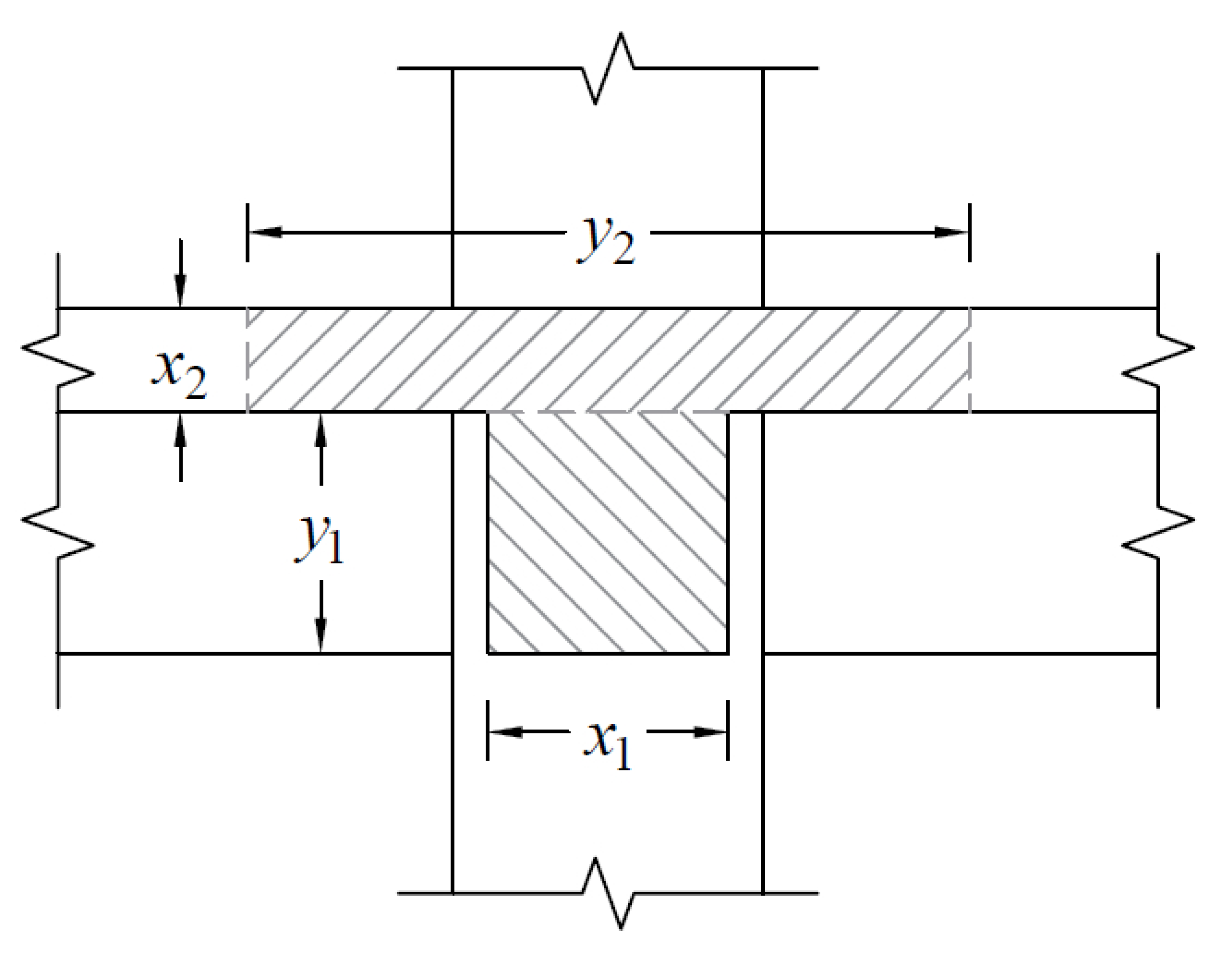
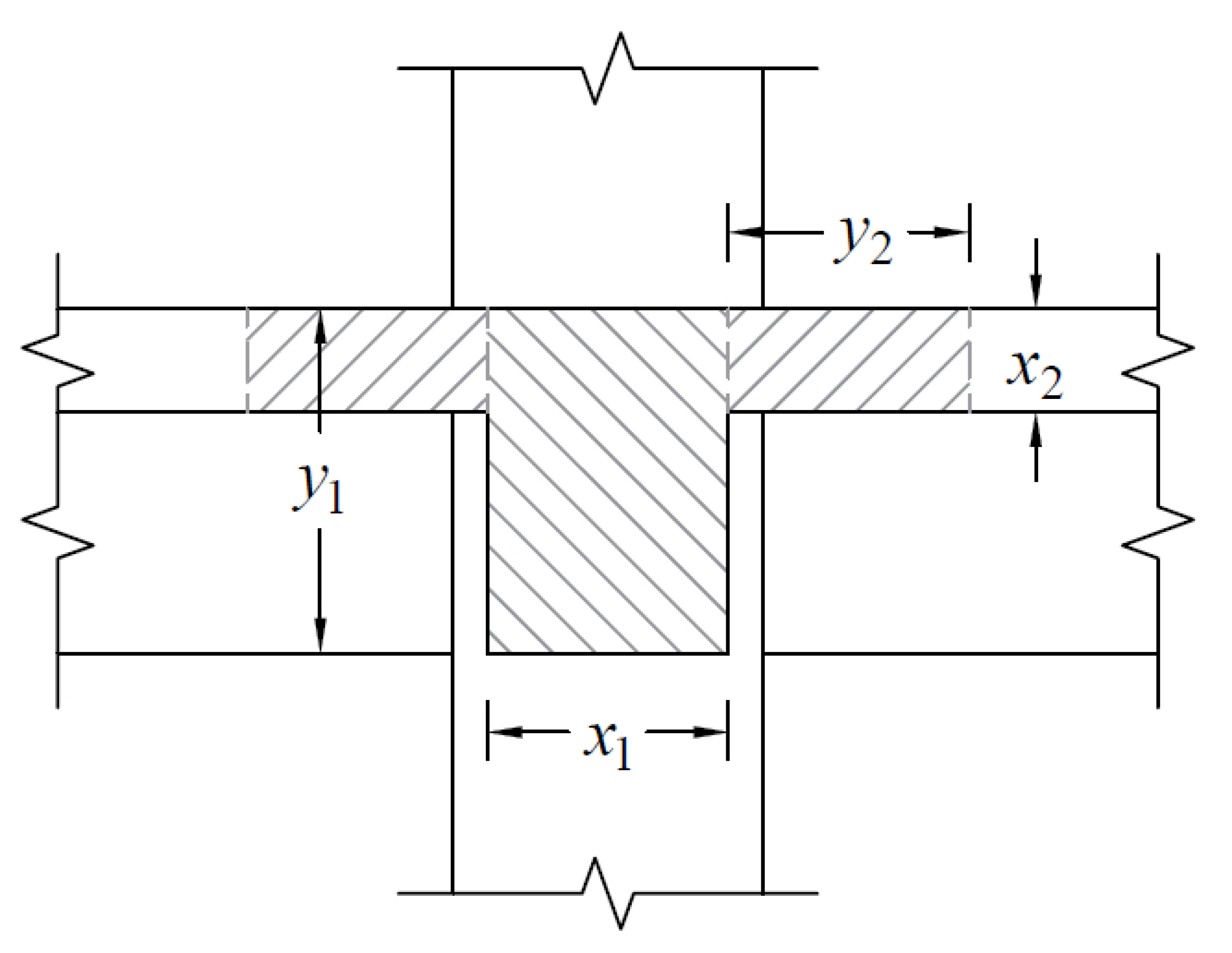
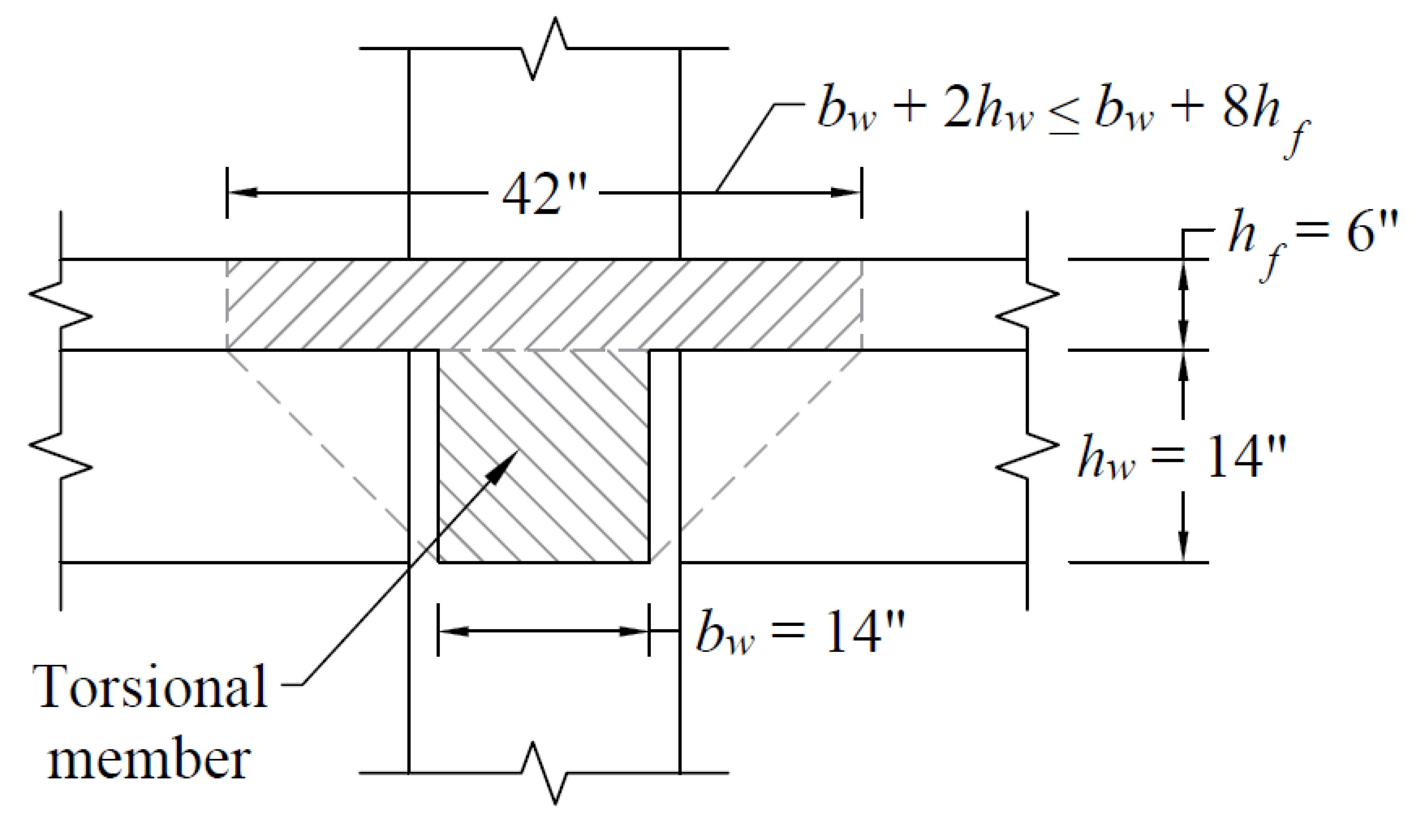
Figure 7 – Attached Torsional Member at Interior Column
For Exterior Columns: | |
| |
Where: | |
| |
| ACI 318-14 (Eq. 8.10.5.2b) |

x1 = 14 in. | x2 = 6 in. | x1 = 14 in. | x2 = 6 in. |
y1 = 21 in. | y2 = 35 in. | y1 = 27 in. | y2 = 21 in. |
C1 = 11,140.64 in.4 | C2 = 2,247.84 in.4 | C1 = 16,628.64 in.4 | C2 = 1,239.84 in.4 |
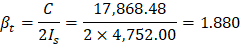
∑C = 11,140.64 + 2,247.84 = 13,388.48 in.4 | ∑C = 16,628.64 + 1,239.84 = 17,868.48 in.4 | ||
|
| ||
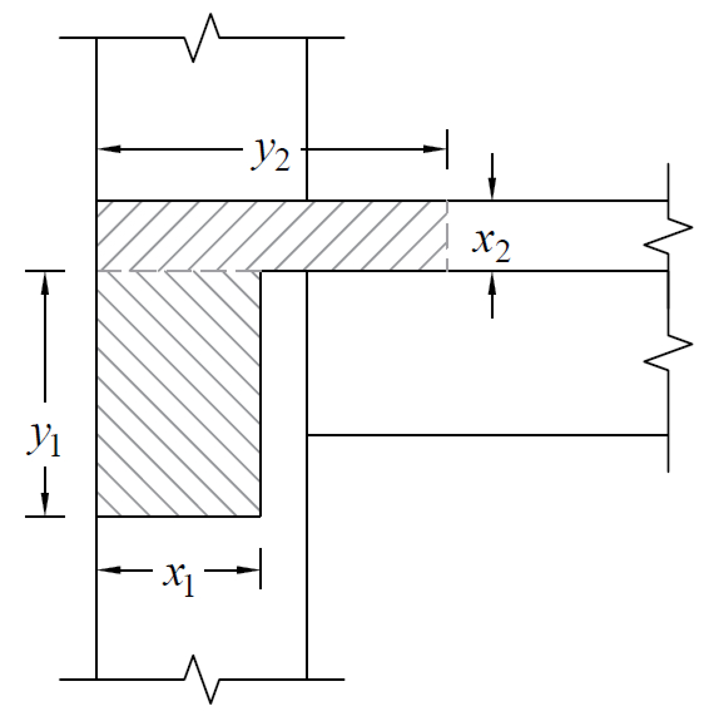
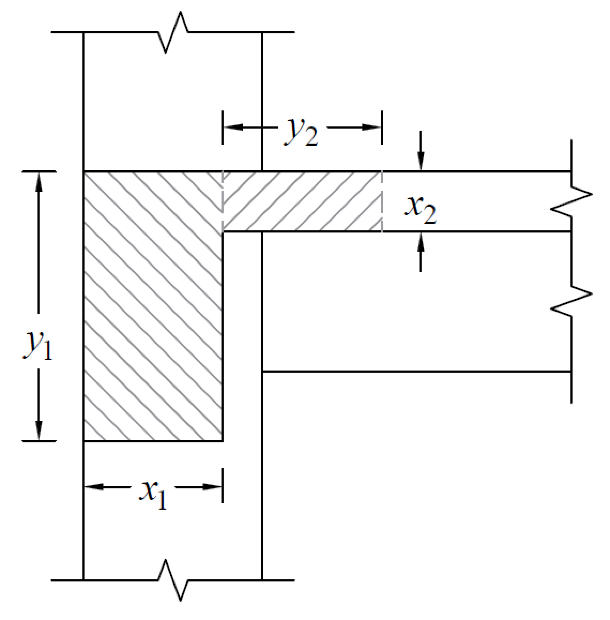
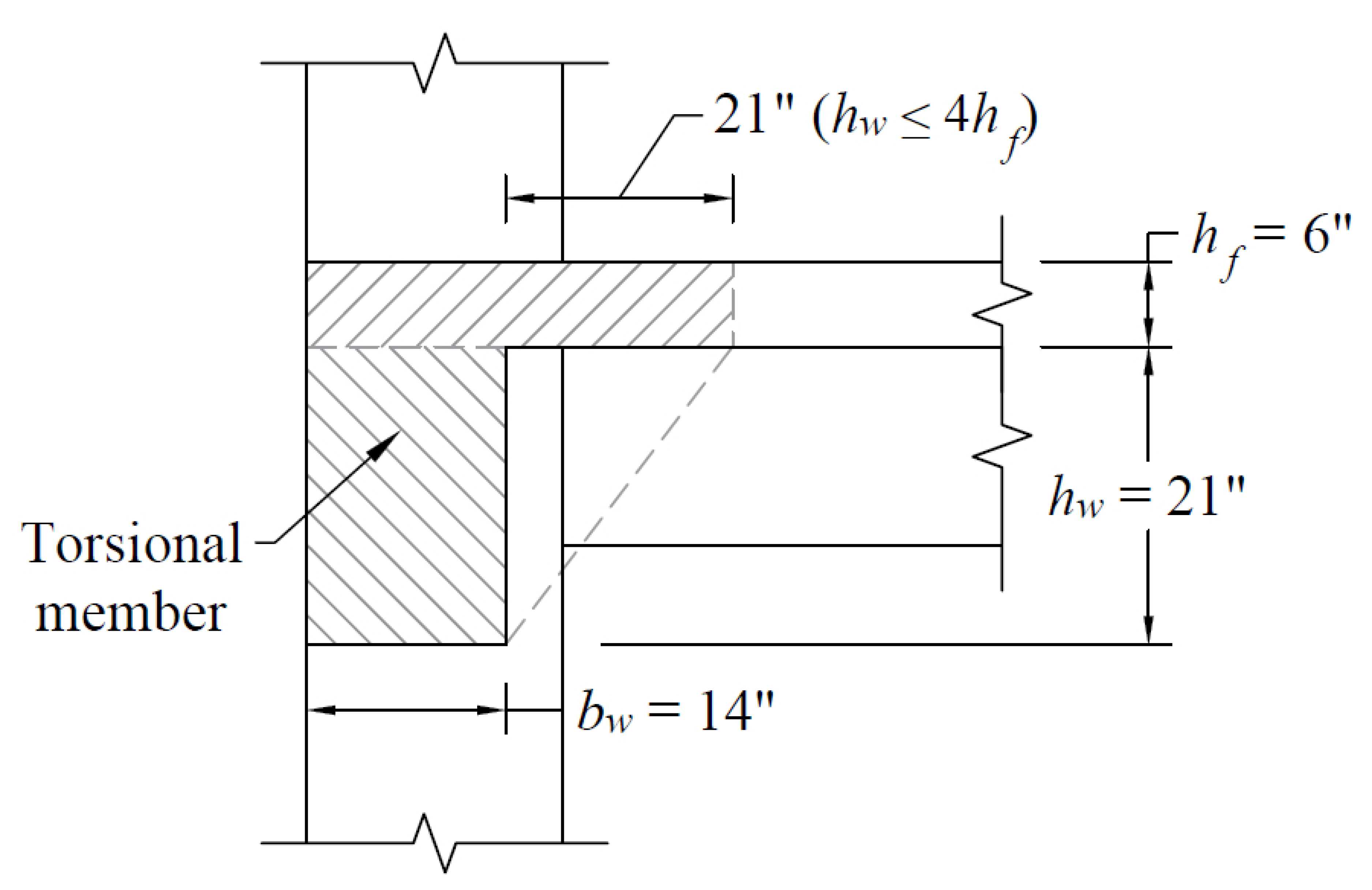
Figure 8 – Attached Torsional Member at Exterior Column
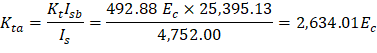
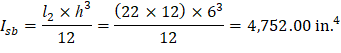
d) Increased torsional stiffness due to parallel beams, Kta
For Interior Columns:
Where:
For Exterior Columns:
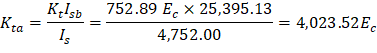
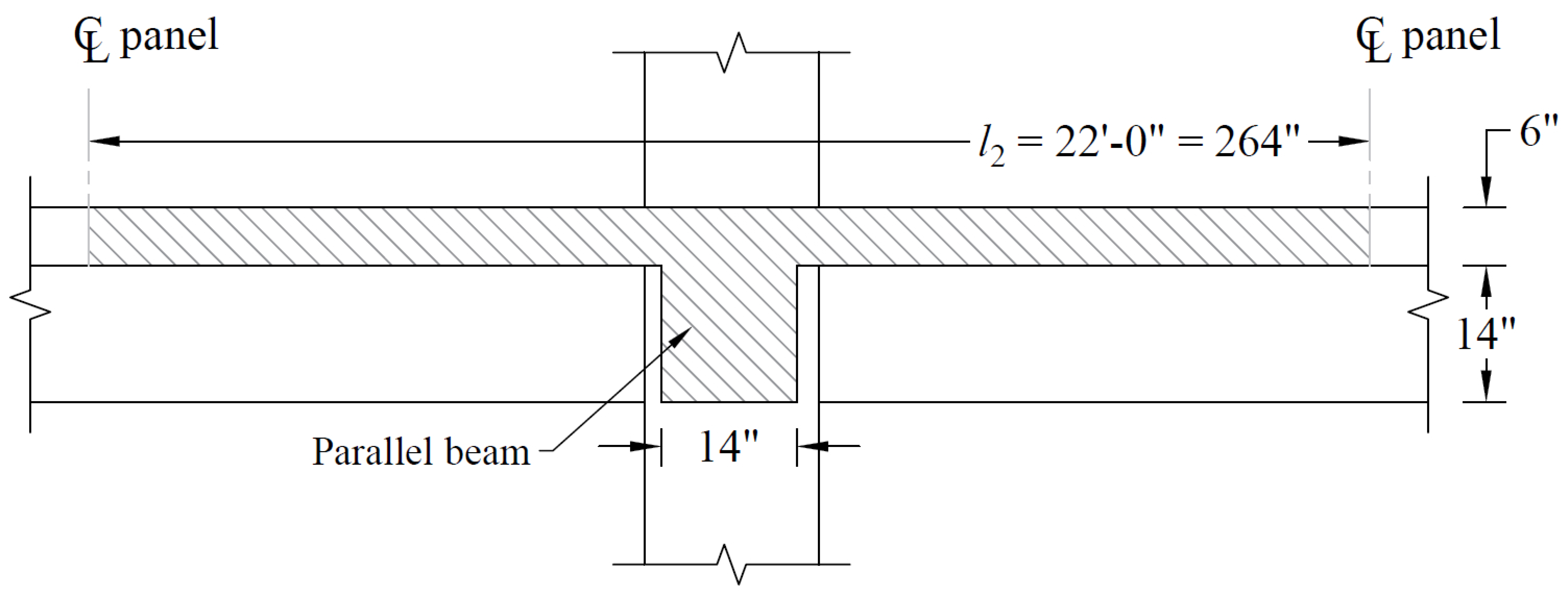
Figure 9 – Slab-Beam in the Direction of Analysis
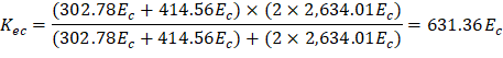
e) Equivalent column stiffness Kec.
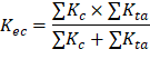
Where ∑ Kta is for two torsional members one on each side of the column, and ∑ Kc is for the upper and lower columns at the slab-beam joint of an intermediate floor.
For Interior Columns:
For Exterior Columns:
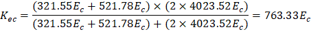
Figure 10 – Equivalent Column Stiffness
f) Slab-beam joint distribution factors, DF.
At exterior joint At interior joint
COF for slab-beam = 0.507
Figure 11 – Slab and Column Stiffness
2.3. Equivalent Frame Analysis
Determine negative and positive moments for the slab-beams using the moment distribution method. With an unfactored live-to dead load ratio:
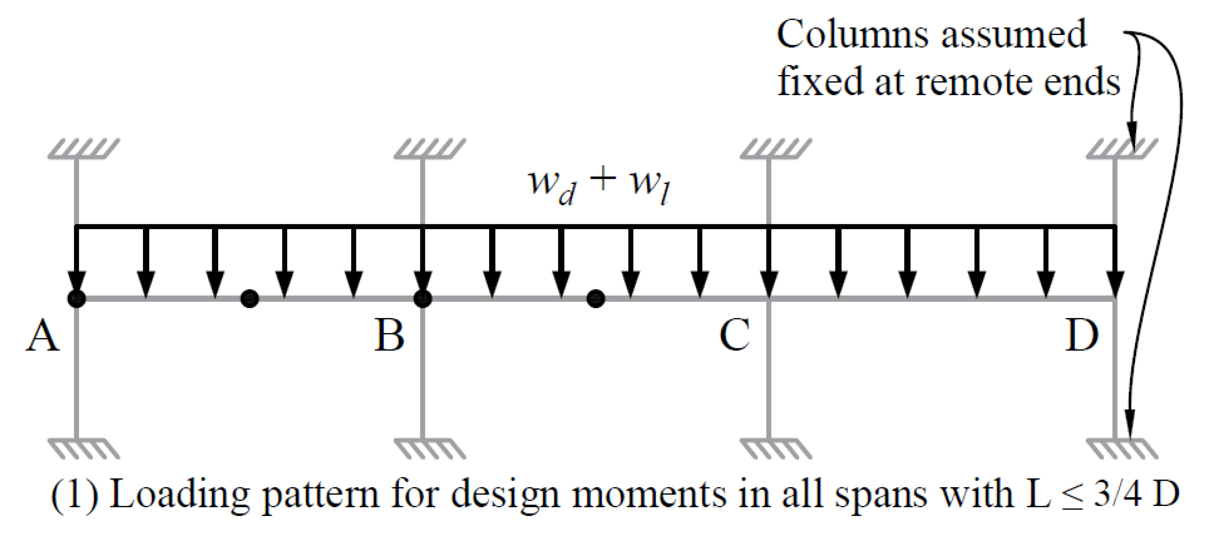
The frame will analyzed for five loading conditions with pattern loading and partial live load as allowed by ACI 318-14 (6.4.3.3).
a) Factored load and Fixed-End Moments (FEM’s).
Factored dead load, Where ( is the weight of beam stem per foot divided by l2) Factored live load, ACI 318-14 (5.3.1) Total factored load,
FEM’s for slab-beam | PCA Notes on ACI 318-11 (Table A1) |
FEM due to | |
FEM due to | |
FEM due to |
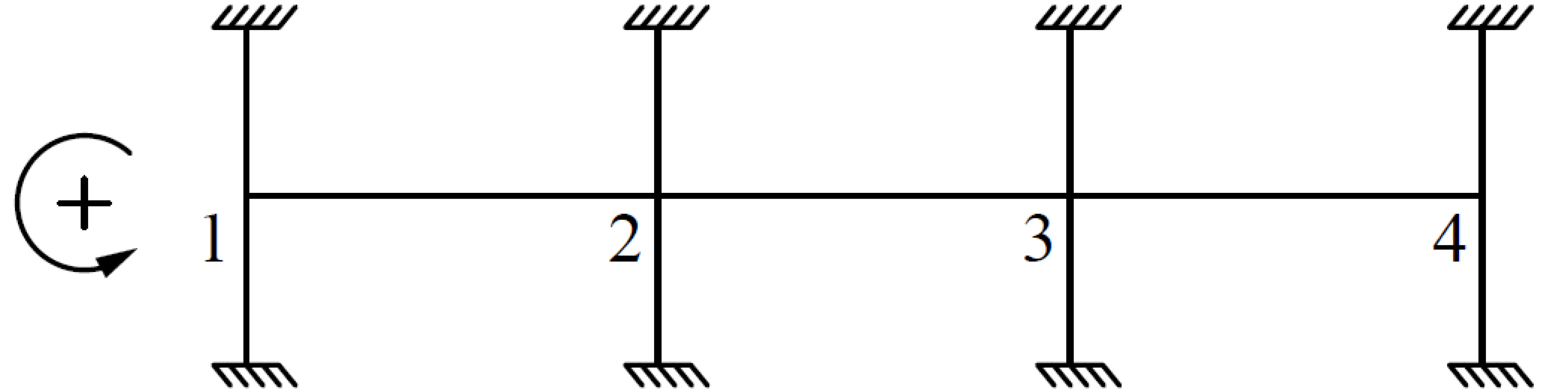
b) Moment distribution.
Moment distribution for the five loading conditions is shown in Table 1. Counter-clockwise rotational moments acting on member ends are taken as positive. Maximum positive span moments are determined from the following equation:
Where:
• Mmax+ | = | Maximum positive moment in the span |
• ML- | = | Negative moment in the left support |
• MR- | = | Negative moment in the right support |
• l1 | = | The span length |
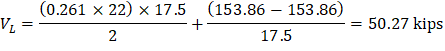
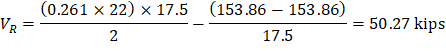
The reactions (shear forces) at supports are given by the following equations:
|
|
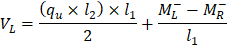
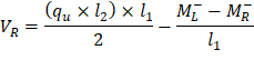
Where:
• VL | = | Reaction (shear force) at the left support |
• VR | = | Reaction (shear force) at the right support |
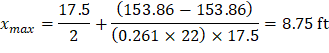
Maximum positive moment in spans 1-2 and 3-4:
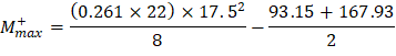
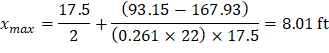
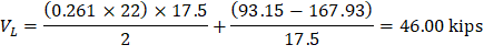
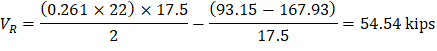
Where:
ML- = 93.15 ft-kips | MR- = 167.93 ft-kips |
Maximum positive moment in spans 2-3:
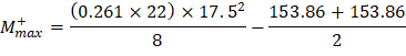
Where:
ML- = 153.86 ft-kips | MR- = 153.86 ft-kips |
Table 1 - Moment Distribution for Partial Frame (Transverse Direction) | |||||||
1 | 2 | 3 | 4 |
| |||
Member | 1-2 | 2-1 | 2-3 | 3-2 | 3-4 | 4-3 | |
DF | 0.395 | 0.306 | 0.306 | 0.306 | 0.306 | 0.395 | |
COF | 0.507 | 0.507 | 0.507 | 0.507 | 0.507 | 0.507 | |
Loading (1) All spans loaded with full factored live load | |||||||
FEM | 148.32 | -148.32 | 148.32 | -148.32 | 148.32 | -148.32 |
|
M-max | 93.15 | -167.93 | 153.86 | -153.86 | 167.93 | -93.15 | |
M+max | 90.97 | 66.06 | 90.97 | ||||
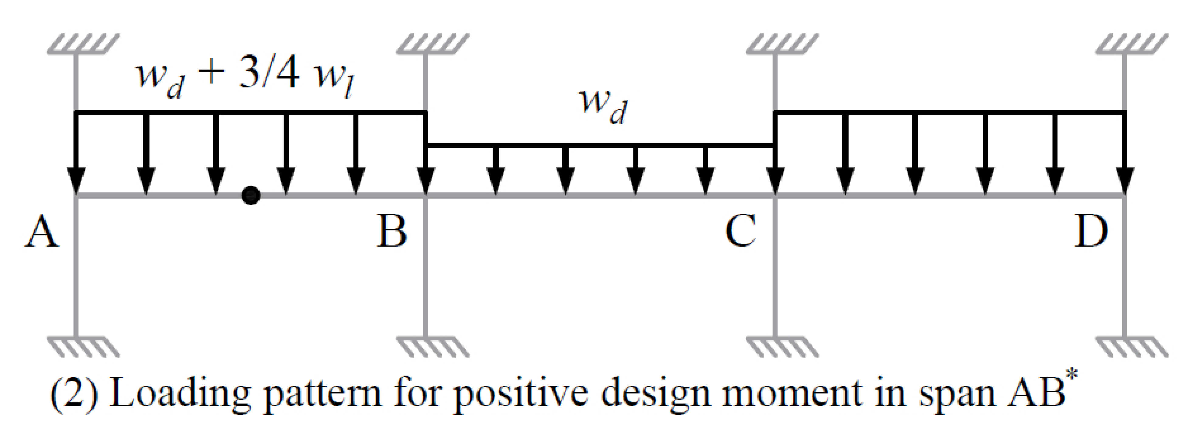
Loading (2) First and third spans loaded with 3/4 factored live load | |||||||
FEM | 125.60 | -125.60 | 57.44 | -57.44 | 125.60 | -125.60 |
|
M-max | 86.72 | -119.15 | 74.81 | -74.81 | 119.15 | -86.72 | |
M+max | 83.66 | 10.36 | 83.66 | ||||
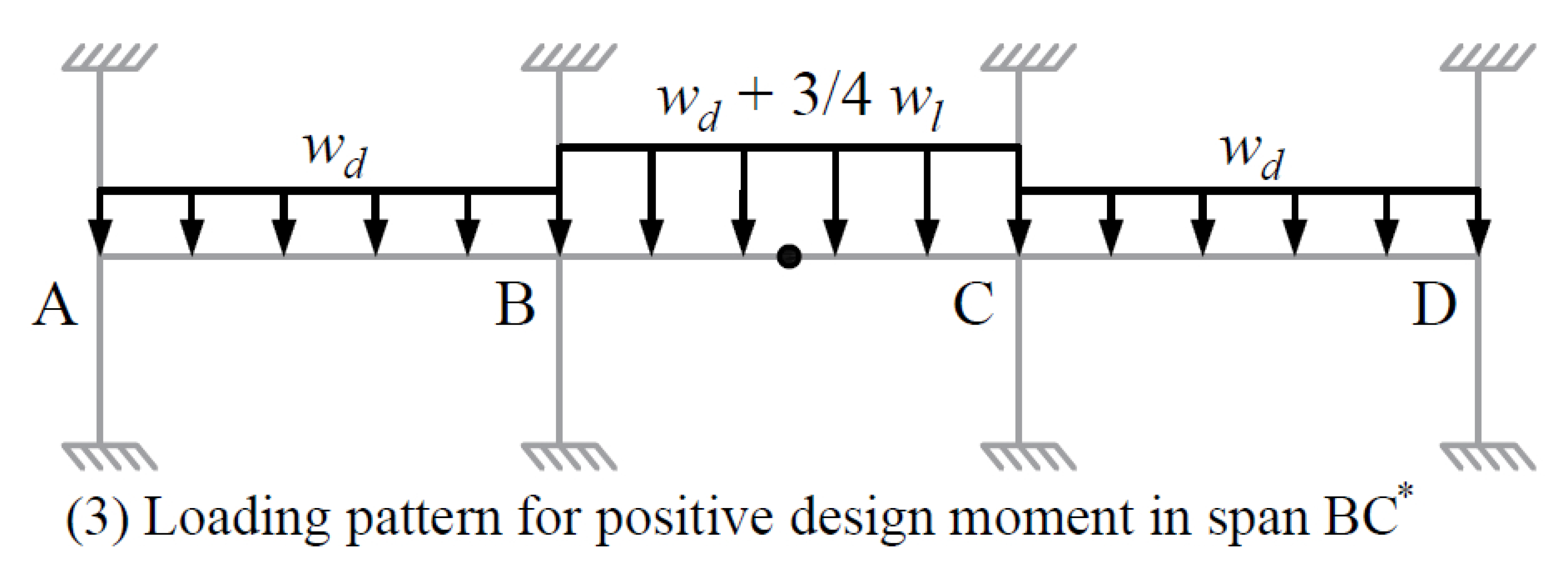
Loading (3) Center span loaded with 3/4 factored live load | |||||||
FEM | 57.44 | -57.44 | 125.60 | 125.60 | 57.44 | -57.44 |
|
M-max | 28.24 | -88.10 | 115.07 | -115.07 | 88.10 | -28.24 | |
M+max | 29.64 | 71.17 | 29.64 | ||||
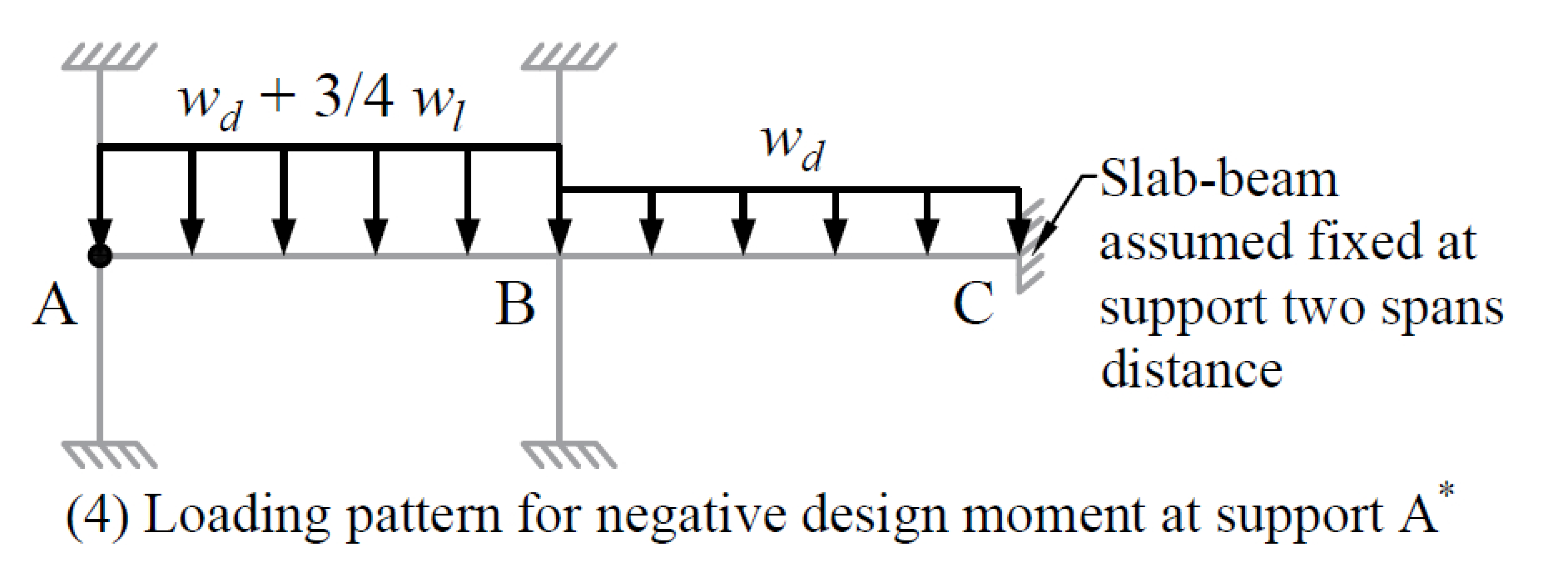
Loading (4) First span loaded with 3/4 factored live load and beam-slab assumed fixed at support two spans away | |||||
FEM | 125.60 | -125.60 | 57.44 | -57.44 |
|
M-max | 85.06 | -124.21 | 86.91 | -42.52 | |
M+max | 82.12 | 21.91 | |||
Loading (5) First and second spans loaded with 3/4 factored live load | |||||||
FEM | 125.60 | -125.60 | 125.60 | -125.60 | 57.44 | -57.44 |
|
M-max | 77.60 | -146.04 | 139.46 | -105.90 | 84.27 | -29.52 | |
M+max | 75.99 | 63.93 | 30.48 | ||||
| ||||||
M-max | 93.15 | -167.93 | 153.86 | -153.86 | 167.93 | -93.15 |
M+max | 90.97 | 71.17 | 90.97 | |||
Positive and negative factored moments for the slab system in the direction of analysis are plotted in Figure 12. The negative design moments are taken at the faces of rectilinear supports but not at distances greater than 0.175 × l1 from the centers of supports.
ACI 318-14 (8.11.6.1) |
(use face of support location)
2.5. Distribution of Design Moments
a) Check whether the moments calculated above can take advantage of the reduction permitted by ACI 318-14 (8.11.6.5):
Slab systems within the limitations of ACI 318-14 (8.10.2) may have the resulting reduced in such proportion that the numerical sum of the positive and average negative moments not be greater than the total static moment Mo given by Equation 8.10.3.2 in the ACI 318-14.
ACI 318-14 (8.11.6.5)
Check Applicability of Direct Design Method:
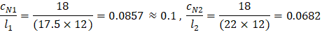
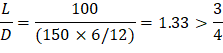
1. There is a minimum of three continuous spans in each direction. ACI 318-14 (8.10.2.1) 2. Successive span lengths are equal. ACI 318-14 (8.10.2.2) 3. Long-to-Short ratio is 22/17.5 = 1.26 < 2.00. ACI 318-14 (8.10.2.3) 4. Column are not offset. ACI 318-14 (8.10.2.4) 5. Loads are gravity and uniformly distributed with service live-to-dead ratio of 1.33 < 2.00 6. Check relative stiffness for slab panel. ACI 318-14 (8.10.2.7) Interior Panel: O.K. ACI 318-14 (Eq. 8.10.2.7a) Interior Panel: O.K. ACI 318-14 (Eq. 8.10.2.7a)

All limitation of ACI 318-14 (8.10.2) are satisfied and the provisions of ACI 318-14 (8.11.6.5) may be applied:
| ACI 318-14 (Eq. 8.10.3.2) |
End spans: | |
Interior span: |

To illustrate proper procedure, the interior span factored moments may be reduced as follows:
Permissible reduction 
Adjusted negative design moment = 117.78 × 0.973 = 114.60 ft-kips
Adjusted positive design moment = 71.17 × 0.973 = 69.24 ft-kips
Mo = 183.84 ft-kips
b) Distribute factored moments to column and middle strips:
The negative and positive factored moments at critical sections may be distributed to the column strip and the two half-middle strips of the slab-beam according to the Direct Design Method (DDM) in 8.10, provided that Eq. 8.10.2.7(a) is satisfied.
ACI 318-14 (8.11.6.6)
Since the relative stiffness of beams are between 0.2 and 5.0 (see Step 2.5), the moments can be distributed across slab-beams as specified in ACI 318-14 (8.10.5 and 6) where:
Where
C = 17,868.48 in.4 (see Figure 8)
Factored moments at critical sections are summarized in Table below.
Factored Moments | Column Strip | Moments in Two Half-Middle Strips** | ||||||
Percent* | Moments | Beam Strip Moment | Column Strip Moment | |||||
End Span | Exterior Negative | 60.27 | 75 | 45.20 | 38.42 | 6.78 | 15.07 | |
Positive | 90.97 | 67 | 60.95 | 51.81 | 9.14 | 30.02 | ||
Interior Negative | 128.64 | 67 | 86.19 | 73.26 | 12.93 | 42.45 | ||
Interior Span | Negative | 117.78 | 67 | 78.91 | 67.07 | 11.84 | 38.87 | |
Positive | 71.17 | 67 | 47.68 | 40.53 | 7.15 | 23.48 | ||
2.6. Flexural Reinforcement Requirements
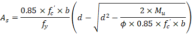
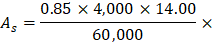
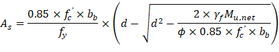
a) Determine flexural reinforcement required for strip moments
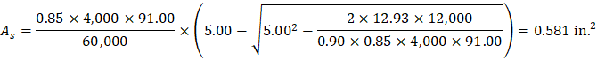
The flexural reinforcement calculation for the column strip of end span - interior negative location is provided below:
Mu = 12.93 ft-kips
Assume tension-controlled section (ϕ = 0.90)
Column strip width, 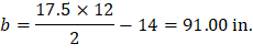
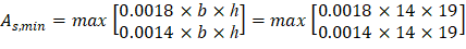
Use average d = 6 – 0.75 – 0.50 / 2 = 5.00 in.


Maximum spacing smax = 2h = 2 × 6 = 12 in. < 18 in.
Provide 8 – #4 bars with As = 1.60 in.2 and s = 91.00 / 8 = 11.38 in. ≤ smax
The flexural reinforcement calculation for the beam strip of end span - interior negative location is provided below:
Mu = 73.26 ft-kips
Assume tension-controlled section (ϕ = 0.90)
Column strip width, b = 14.00 in.
Use average d = 20 – 0.75 – 0.50 / 2 = 19.00 in.
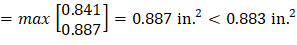
Provide 5 – #4 bars with As = 1.00 in.2
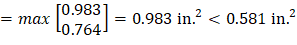
All the values in Table below are calculated based on the procedure outlined above.
Table 3 - Required Slab Reinforcement for Flexure [Equivalent Frame Method (EFM)] Mu b * d ** As Req’d for flexure Min As† †† Reinforcement Provided As Prov. for flexure End Span Exterior Negative 38.42 14 19.00 0.456 0.608 4 – #4 0.80 Positive 51.81 14 18.25 0.645 0.852 5 – #4 1.00 Interior Negative 73.26 14 19.00 0.883 0.887 5 – #4 1.00 Exterior Negative 6.78 91 5.00 0.303 0.983 8 – #4 1.60 Positive 9.14 91 5.00 0.410 0.983 8 – #4 1.60 Interior Negative 12.93 91 5.00 0.581 0.983 8 – #4 1.60 Exterior Negative 15.07 159 5.00 0.675 1.717 14 – #4 2.80 Positive 30.02 159 5.00 1.355 1.717 14 – #4 2.80 Interior Negative 42.45 159 5.00 1.928 1.717 14 – #4 2.80 Interior Span Beam Strip Positive 40.53 14 18.25 0.502 0.670 4 – #4 0.80 Column Strip Positive 7.15 91 5.00 0.320 0.983 8 – #4 1.60 Middle Strip Positive 23.48 159 5.00 1.056 1.717 14 – #4 2.80
(ft-kips)
(in.)
(in.)
(in.2)
(in.2)
(in.2)
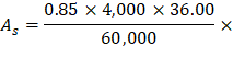
b) Calculate additional slab reinforcement at columns for moment transfer between slab and column by flexure
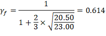
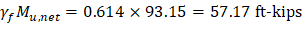
Portion of the unbalanced moment transferred by flexure is γf × Mu | ACI 318-14 (8.4.2.3.1) |
Where: | |
ACI 318-14 (8.4.2.3.2) |
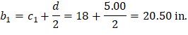
• b1 | = | Dimension of the critical section bo measured in the direction of the span for which moments are determined in ACI 318, Chapter 8 (see Figure 13). | |
• b2 | = | Dimension of the critical section bo measured in the direction perpendicular to b1 in ACI 318, Chapter 8 (see Figure 13). | |
• bo | = | Perimeter of critical section for two-way shear in slabs and footings. | |
• bb | = | Effective slab width = c2 + 3×h | ACI 318-14 (8.4.2.3.3) |
Figure 13 – Critical Shear Perimeters for Columns
For Exterior Column:
| |
|
|
| |
| |
| |
| |
| |
| |
| |
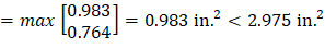
⸫ Additional slab reinforcement at the exterior column is required. | |
| |
Use 10 – #4 → Aprovided,add = 10 × 0.20 = 2.00 in.2 < Areq’d,add = 1.788 in.2 | |


Based on the procedure outlined above, values for all supports are given in Table below.
Table 4 - Additional Slab Reinforcement at columns for moment transfer between slab and column [Equivalent Frame Method (EFM)] | |||||||||
Span Location | Effective slab width, bb (in.) | d (in.) | γf | Mu* (ft-kips) | γf Mu (ft-kips) | As req’d within | As prov. for flexure | Add’l Reinf. | |
End Span | |||||||||
Column Strip | Exterior Negative | 36.00 | 5.00 | 0.614 | 93.15 | 57.17 | 2.975 | 1.187 | 10-#4 |
Interior Negative | 36.00 | 5.00 | 0.600 | 44.34 | 26.60 | 1.260 | 1.387 | - | |
* Mu is taken at the centerline of the support in Equivalent Frame Method solution. | |||||||||
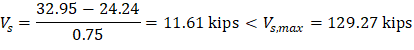
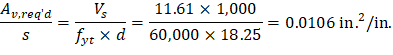
c) Determine transverse reinforcement required for beam strip shear
The transverse reinforcement calculation for the beam strip of end span – exterior location is provided below.
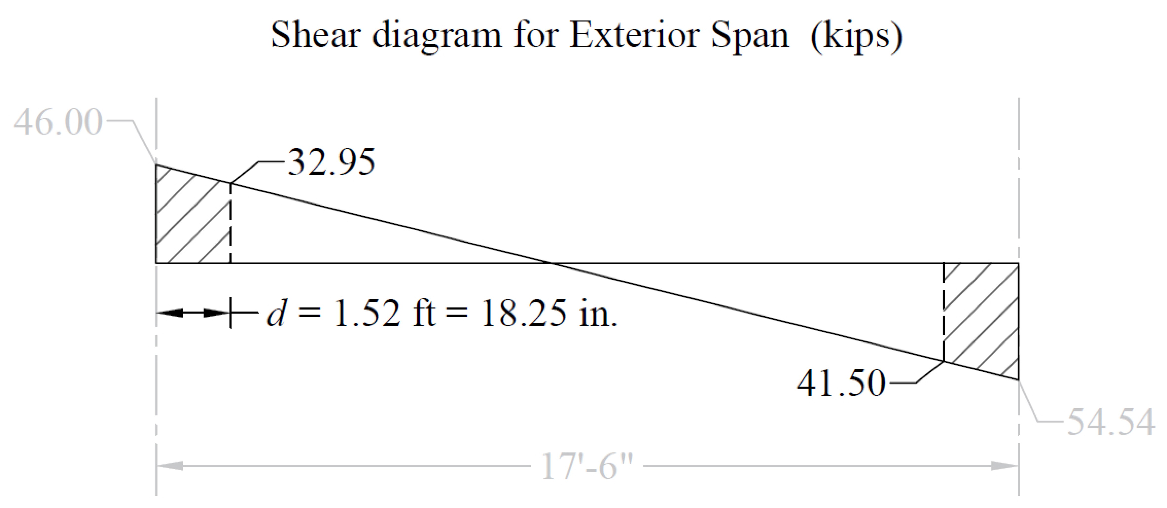
Figure 14 – Shear at Critical Sections for the End Span (at distance d from the face of the column)

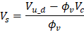
The required shear at a distance d from the face of the supporting column Vu_d = 31.64 kips (Figure 14).
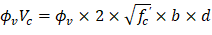
| ACI 318-14 (22.5.5.1) |
| ⸫Stirrups are required. |
Distance from the column face beyond which minimum reinforcement is required: | |
| ACI 318-14 (22.5.10.1) |
| O.K. |
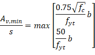
| ACI 318-14 (22.5.10.1) |
| ACI 318-14 (22.5.10.5.3) |
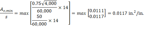
| ACI 318-14 (9.6.3.3) |
| |
| |
| |
| |
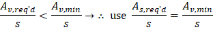
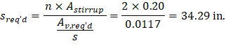
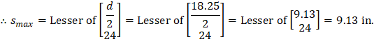
| ACI 318-14 (9.7.6.2.2) |
Since sreq'd > smax → use smax | |
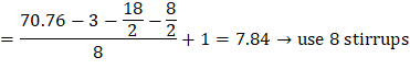
Select sprovided = 8 in. #4 stirrups with first stirrup located at distance 3 in. from the column face. | |
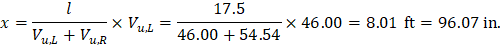
The distance where the shear is zero is calculated as follows: | |
| |
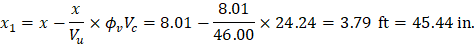
The distance from support beyond which minimum reinforcement is required is calculated as follows: | |
| |
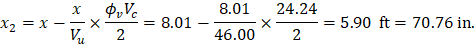
The distance at which no shear reinforcement is required is calculated as follows: | |
| |
| |


All the values in Table below are calculated based on the procedure outlined above.
Table 5 – Required Beam Reinforcement for Shear | |||||
Span Location | Av,min/s | Av,req’d/s | sreq’d | smax | Reinforcement Provided |
End Span | |||||
Exterior | 0.0117 | 0.0106 | 34.29 | 9.13 | 8 – #4 @ 8 in.* |
Interior | 0.0117 | 0.0210 | 19.04 | 9.13 | 10 – #4 @ 8.6 in. |
Interior Span | |||||
Interior | 0.0117 | 0.0158 | 25.30 | 9.13 | 9 – #4 @ 8.6 in. |
* Minimum transverse reinforcement governs | |||||
The unbalanced moment from the slab-beams at the supports of the equivalent frame are distributed to the actual columns above and below the slab-beam in proportion to the relative stiffness of the actual columns. Referring to Table 1, the unbalanced moment at joints 1 and 2 are:
Joint 1 = + 93.15 ft-kips
Joint 2 = -119.15 + 74.81 = -44.34 ft-kips
The stiffness and carry-over factors of the actual columns and the distribution of the unbalanced moments to the exterior and interior columns are shown in the following Figure.
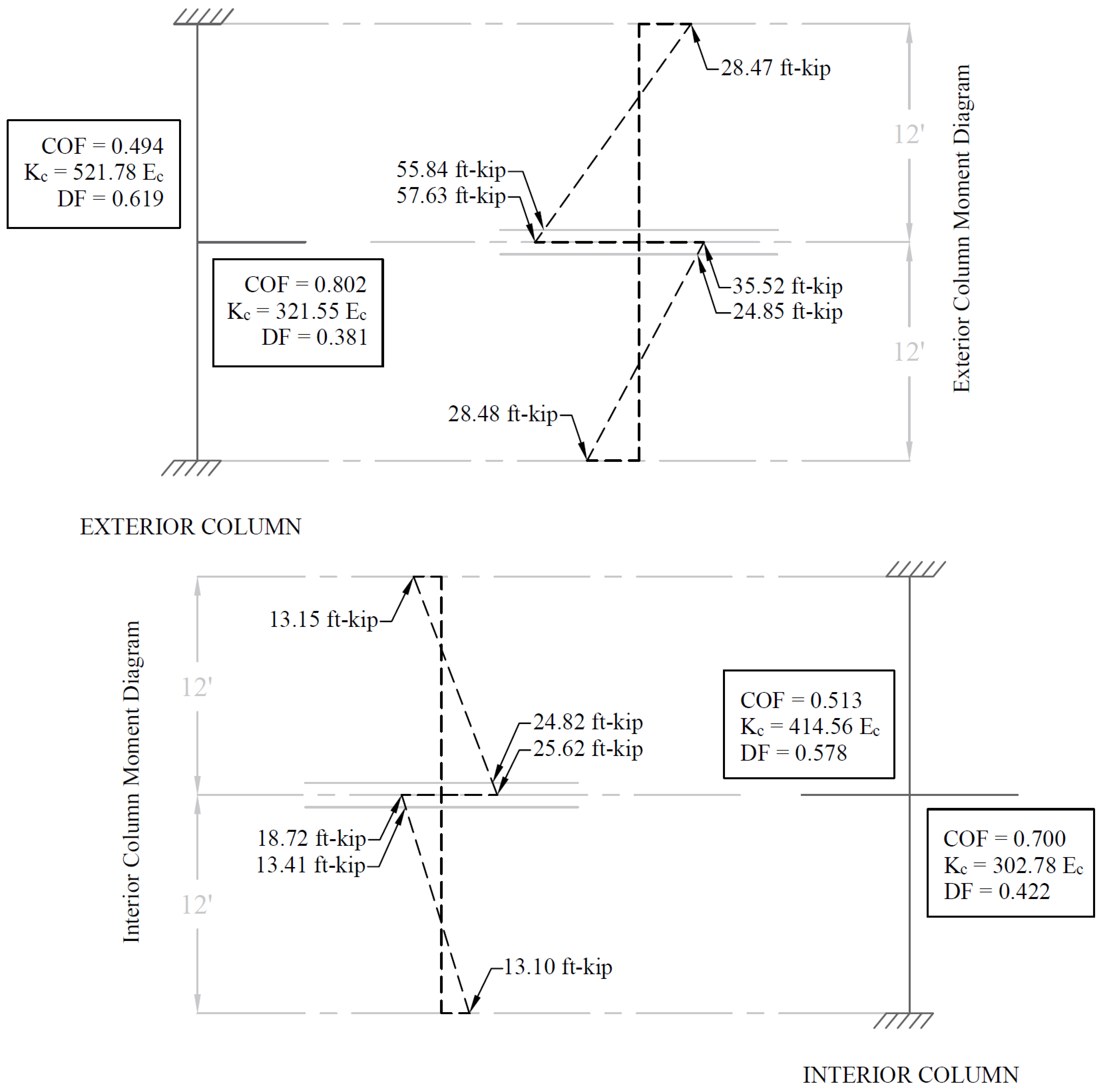
Figure 15 – Column Moments (Unbalanced Moments from Slab-Beam)
Design moment in exterior column = 55.84 ft-kips
Design moment in interior column = 24.82 ft-kips
The moments determined above are combined with the factored axial loads (for each story) and factored moments in the transverse direction for design of column sections. A detailed analysis to obtain the moment values at the face of interior, exterior, and corner columns from the unbalanced moment values can be found in the “Two-Way Flat Plate Concrete Floor System Analysis and Design (ACI 318-14)”