2. Flexural Analysis and Design
ACI 318 states that a slab system shall be designed by any procedure satisfying equilibrium and geometric compatibility, provided that strength and serviceability criteria are satisfied. Distinction of two-systems from one-way systems is given by ACI 318-14 (R8.10.2.3 & R8.3.1.2).
ACI 318 permits the use of Direct Design Method (DDM) and Equivalent Frame Method (EFM) for the gravity load analysis of orthogonal frames and is applicable to flat plates, flat slabs, and slabs with beams. The following sections outline the solution per EFM and spSlab software. For the solution per DDM, check the “Two-Way Flat Plate Concrete Floor System Analysis and Design (ACI 318-14)” example.
2.1. Equivalent Frame Method (EFM)
EFM is the most comprehensive and detailed procedure provided by the ACI 318 for the analysis and design of two-way slab systems where the structure is modeled by a series of equivalent frames (interior and exterior) on column lines taken longitudinally and transversely through the building.
The equivalent frame consists of three parts (for a detailed discussion of this method, refer to “Two-Way Flat Plate Concrete Floor System Analysis and Design (ACI 318-14)”:
1) Horizontal slab-beam strip
2) Columns or other vertical supporting members.
3) Elements of the structure (Torsional members) that provide moment transfer between the horizontal and vertical members.
2.1.1. Limitations for Use of Equivalent Frame Method
In EFM, live load shall be arranged in accordance with 6.4.3 which requires slab systems to be analyzed and designed for the most demanding set of forces established by investigating the effects of live load placed in various critical patterns.
ACI 318-14 (8.11.1.2 & 6.4.3)
Complete analysis must include representative interior and exterior equivalent frames in both the longitudinal and transverse directions of the floor.
ACI 318-14 (8.11.2.1)
Panels shall be rectangular, with a ratio of longer to shorter panel dimensions, measured center-to-center of supports, not to exceed 2.
ACI 318-14 (8.10.2.3)
2.1.2. Frame Members of Equivalent Frame
Determine moment distribution factors and fixed-end moments for the equivalent frame members. The moment distribution procedure will be used to analyze the equivalent frame. Stiffness factors k, carry over factors COF, and fixed-end moment factors FEM for the slab-beams and column members are determined using the design aids tables at Appendix 20A of PCA Notes on ACI 318-11. These calculations are shown below.
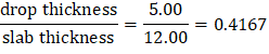
a) Flexural stiffness of slab-beams at both ends, Ksb
| |
Slab thickness = h = hMI = 12.00 in. and drop thickness = dMI – hMI = 17.00 – 12.00 = 5.00 in. | |
| |
For cF1 = cF2, stiffness factors, kNF = kFN = 5.541 | PCA Notes on ACI 318-11 (Table A2 & A3) |
Thus, | PCA Notes on ACI 318-11 (Table A2 & A3) |
Where, | |
ACI 318-14 (19.2.2.1.a) | |
Carry-over factor COF = 0.576 | PCA Notes on ACI 318-11 (Table A2 & A3) |
Fixed-end moment | PCA Notes on ACI 318-11 (Table A2 & A3) |
Uniform load fixed end moment coefficient, mNF1 = 0.0913
Fixed end moment coefficient for (b-a) = 0.2 when a = 0, mNF2 = 0.0162
Fixed end moment coefficient for (b-a) = 0.2 when a = 0.8, mNF3 = 0.0020
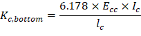
b) Flexural stiffness of column members at both ends, Kc
Referring to Table A7, Appendix 20A,
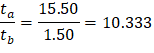
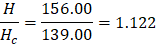
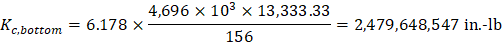
For the Bottom Column (Below):
ta = 3.00 / 2 + 14.00 = 15.50 in. | tb = 3.00 / 2 = 1.50 in. |
H = 13 ft = 156.00 in. | Hc = H - ta - tb = 156.00 – 15.50 – 1.50 = 139.00 in. |
Then, | |
|
|
Thus, kAB = 6.178 and CAB = 0.500 by interpolation.
| PCA Notes on ACI 318-11 (Table A7) |
| |
Where | |
| ACI 318-14 (19.2.2.1.a) |
lc = 13 ft = 156 in. |

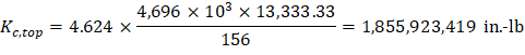
For the Top Column (Above):

Thus, kAB = 4.624 and CAB = 0.667 by interpolation.
PCA Notes on ACI 318-11 (Table A7)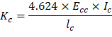
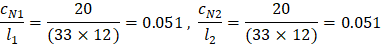
c) Torsional stiffness of torsional members, Kt.
ACI 318-14 (R.8.11.5) Where ACI 318-14 (Eq. 8.10.5.2b) c2 = 20 in., l2 = 33 ft = 396 in.
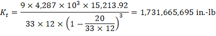
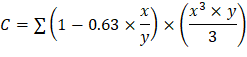
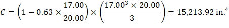
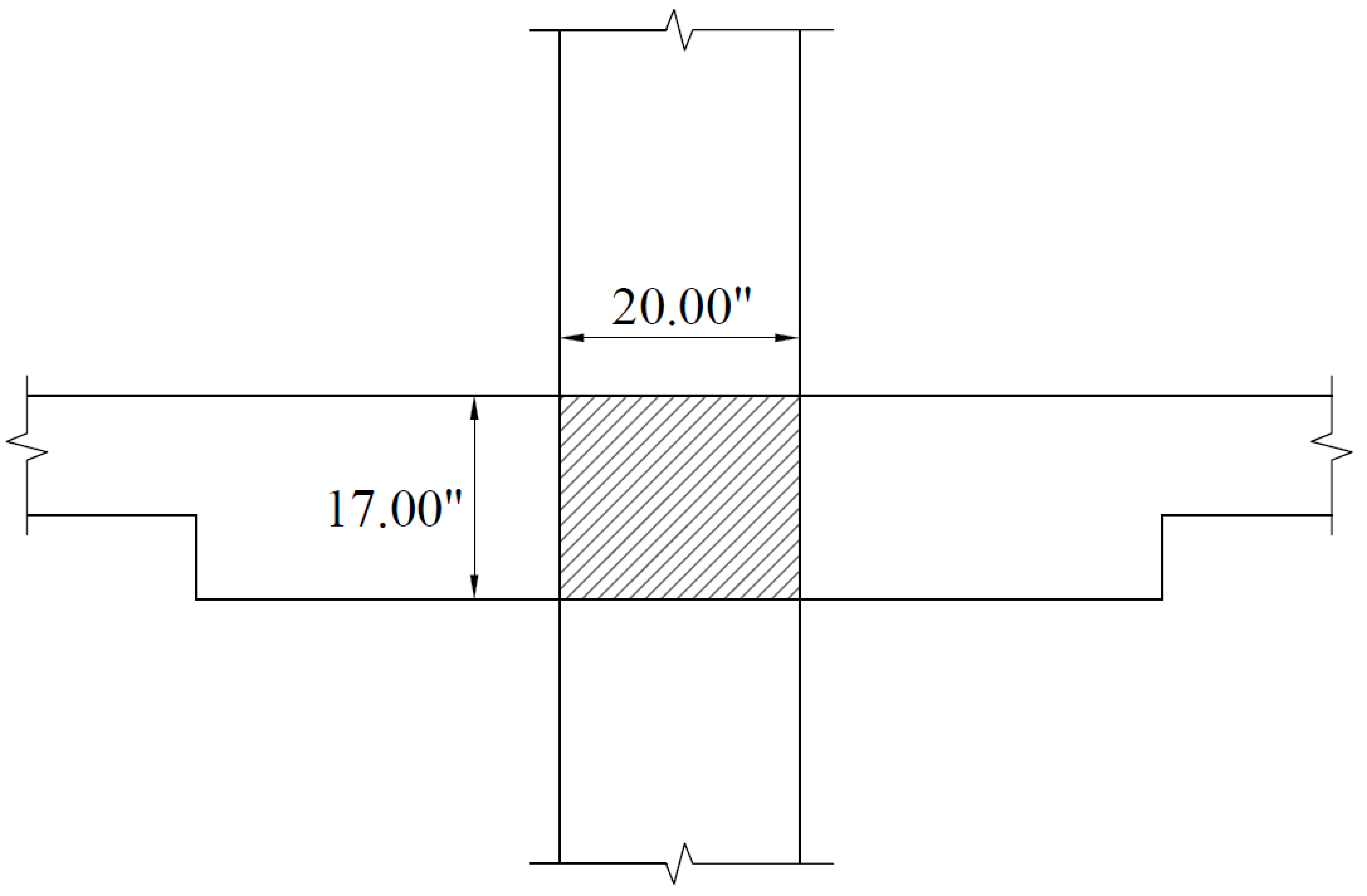
Figure 15 – Torsional Member
d) Equivalent column stiffness Kec.
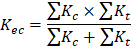

Where ΣKt is for two torsional members one on each side of the column, and ΣKc is for the upper and lower columns at the slab-beam joint of an intermediate floor.
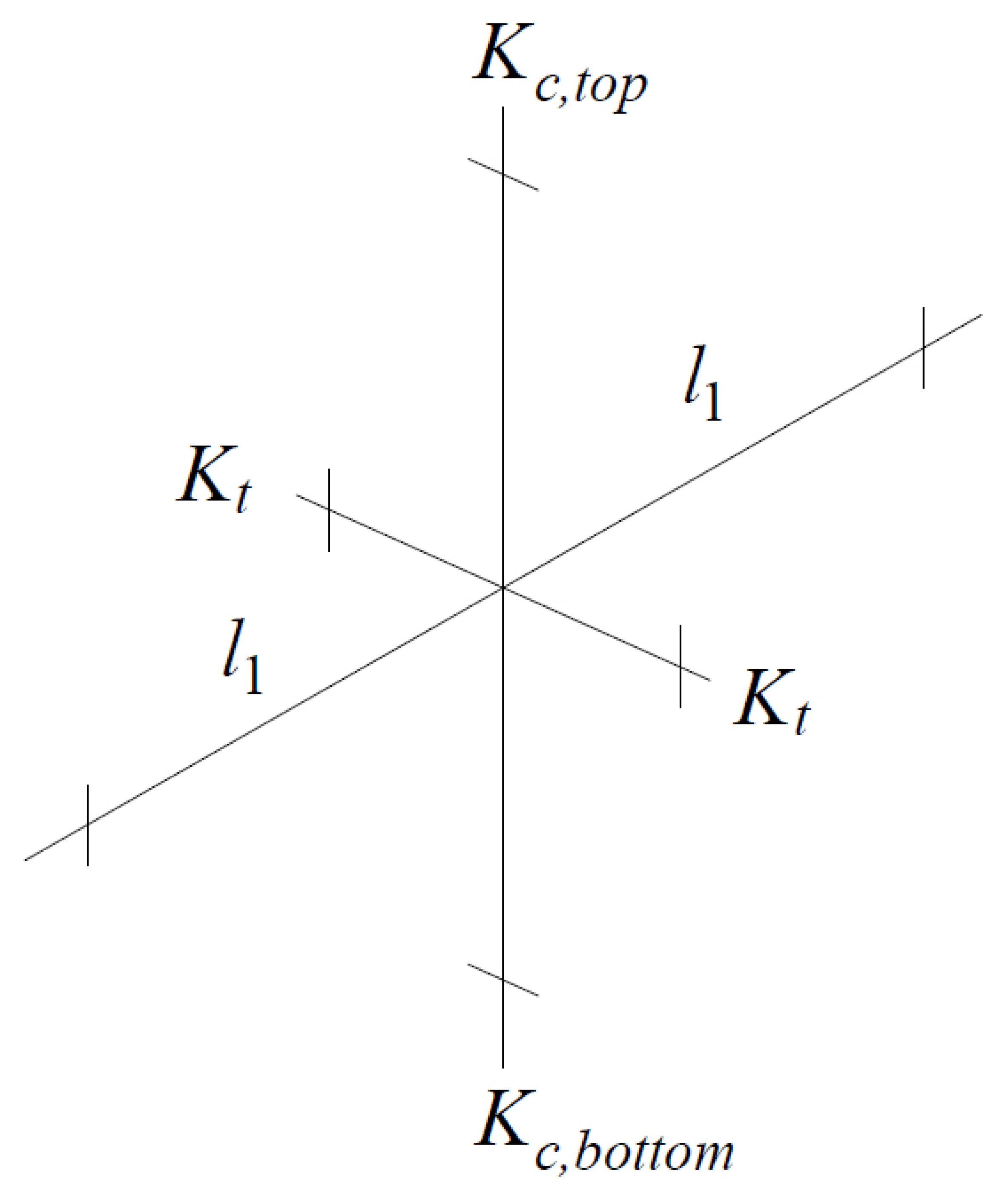
Figure 16 – Column and Edge of Slab
e) Slab-beam joint distribution factors, DF.
At exterior joint At interior joint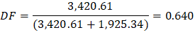
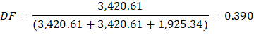
COF for slab-beam = 0.576
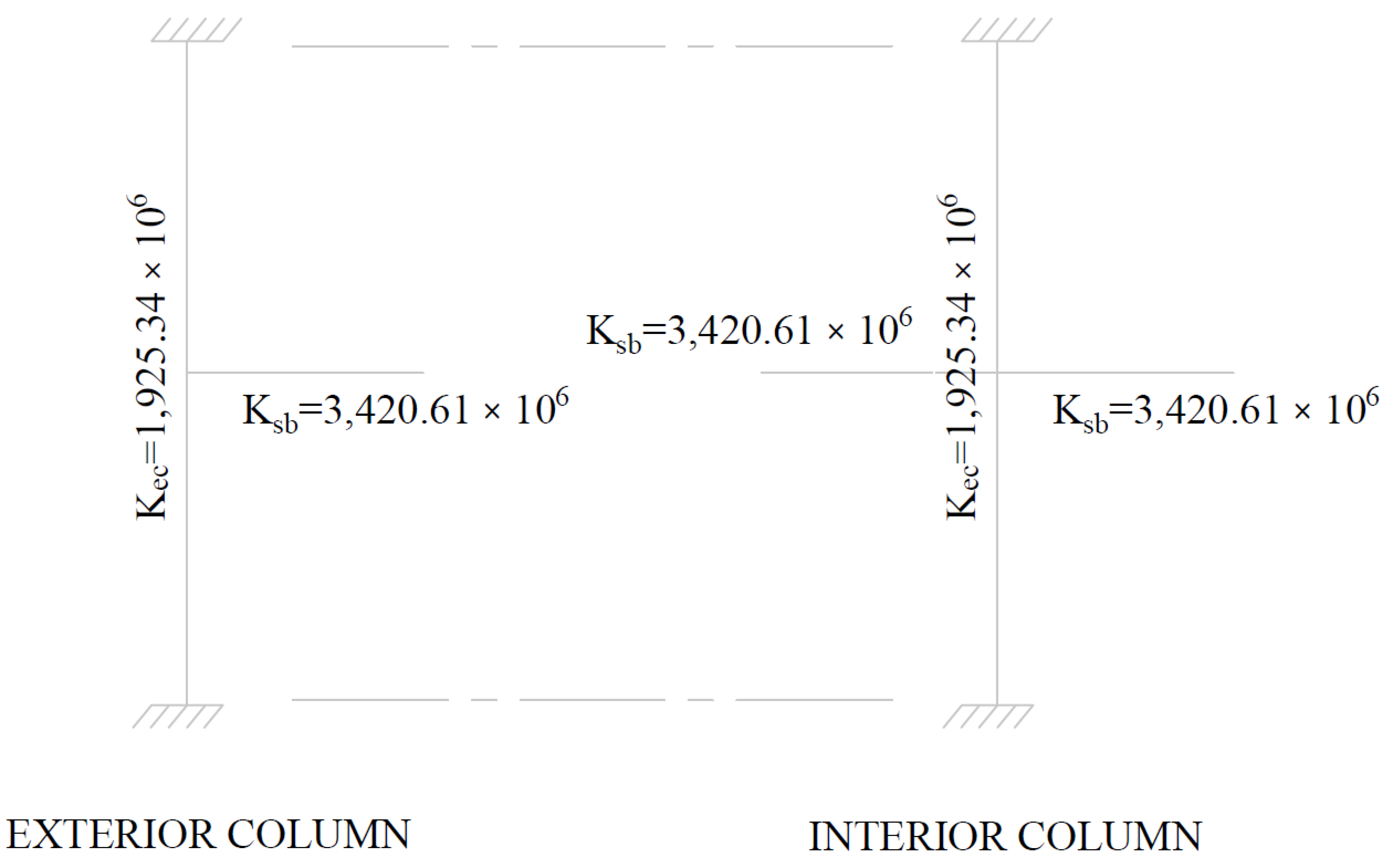
Figure 17 – Slab and Column Stiffness
2.1.3. Equivalent Frame Analysis
Determine negative and positive moments for the slab-beams using the moment distribution method. Since the unfactored live load does not exceed three-quarters of the unfactored dead load, design moments are assumed to occur at all critical sections with full factored live on all spans.
ACI 318-14 (6.4.3.2)
a) Factored load and Fixed-End Moments (FEM’s).
For slab:
Factored dead load, Factored live load, ACI 318-14 (5.3.1) Total factored load,
For drop panels:
Factored dead load, | ||
Factored live load, | ACI 318-14 (5.3.1) | |
Total factored load, |
Fixed-end moment | PCA Notes on ACI 318-11 (Table A2 & A3) |
| |
|

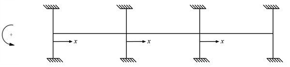
b) Moment distribution. Computations are shown in the Table 1 Counterclockwise rotational moments acting on the member ends are taken as positive.
Joint | 1 | 2 | 3 | 4 | ||
Member | 1-2 | 2-1 | 2-3 | 3-2 | 3-4 | 4-3 |
DF | 0.640 | 0.390 | 0.390 | 0.390 | 0.390 | 0.640 |
COF | 0.576 | 0.576 | 0.576 | 0.576 | 0.576 | 0.576 |
FEM | 1,147.66 | -1,147.66 | 1,147.66 | -1,147.66 | 1,147.66 | -1,147.66 |
Dist | -734.33 | 0 | 0 | 0 | 0 | 734.33 |
CO | 0 | -422.89 | 0 | 0 | 422.89 | 0 |
Dist | 0 | 165.01 | 165.01 | -165.01 | -165.01 | 0 |
CO | 95.03 | 0 | -95.03 | 95.03 | 0 | -95.03 |
Dist | -60.80 | 37.08 | 37.08 | -37.08 | -37.08 | 60.80 |
CO | 21.35 | -35.01 | -21.35 | 21.35 | 35.01 | -21.35 |
Dist | -13.66 | 21.99 | 21.99 | -21.99 | -21.99 | 13.66 |
CO | 12.67 | -7.87 | -12.67 | 12.67 | 7.87 | -12.67 |
Dist | -8.10 | 8.01 | 8.01 | -8.01 | -8.01 | 8.10 |
CO | 4.61 | -4.67 | -4.61 | 4.61 | 4.67 | -4.61 |
Dist | -2.95 | 3.62 | 3.62 | -3.62 | -3.62 | 2.95 |
CO | 2.09 | -1.70 | -2.09 | 2.09 | 1.70 | -2.09 |
Dist | -1.33 | 1.48 | 1.48 | -1.48 | -1.48 | 1.33 |
CO | 0.85 | -0.77 | -0.85 | 0.85 | 0.77 | -0.85 |
Dist | -0.54 | 0.63 | 0.63 | -0.63 | -0.63 | 0.54 |
CO | 0.36 | -0.31 | -0.36 | 0.36 | 0.31 | -0.36 |
Dist | -0.23 | 0.26 | 0.26 | -0.26 | -0.26 | 0.23 |
CO | 0.15 | -0.13 | -0.15 | 0.15 | 0.13 | -0.15 |
Dist | -0.10 | 0.11 | 0.11 | -0.11 | -0.11 | 0.10 |
CO | 0.06 | -0.06 | -0.06 | 0.06 | 0.06 | -0.06 |
Dist | -0.04 | 0.05 | 0.05 | -0.05 | -0.05 | 0.04 |
CO | 0.03 | -0.02 | -0.03 | 0.03 | 0.02 | -0.03 |
Dist | -0.02 | 0.02 | 0.02 | -0.02 | -0.02 | 0.02 |
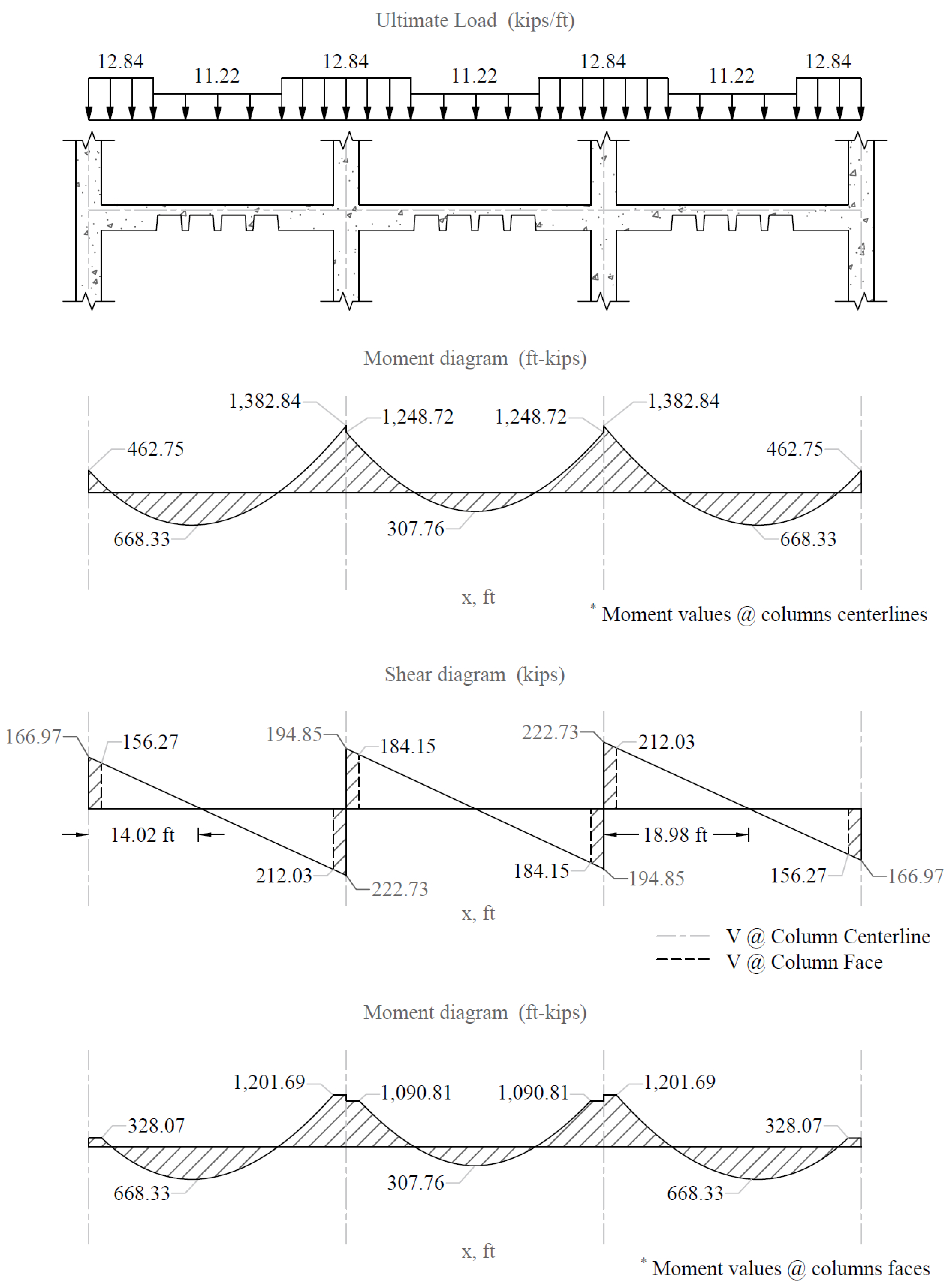
M-max | 462.75 | -1,382.84 | 1,248.72 | -1,248.72 | 1,382.84 | -462.75 |
V | 166.97 | -222.73 | 194.85 | -194.85 | 222.73 | -166.97 |
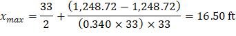
xmax | 14.02 | 16.50 | 18.98 | |||
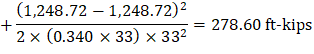
M+max | 668.33 | 307.76 | 668.33 | |||
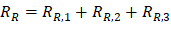
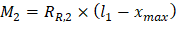
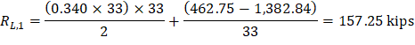
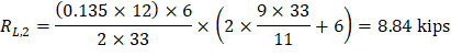
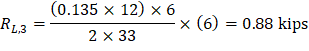
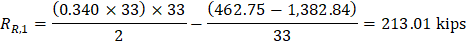
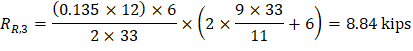
Maximum positive span moments are determined from the following equations:
|
|
|
|
|
|
|
|
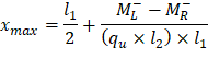
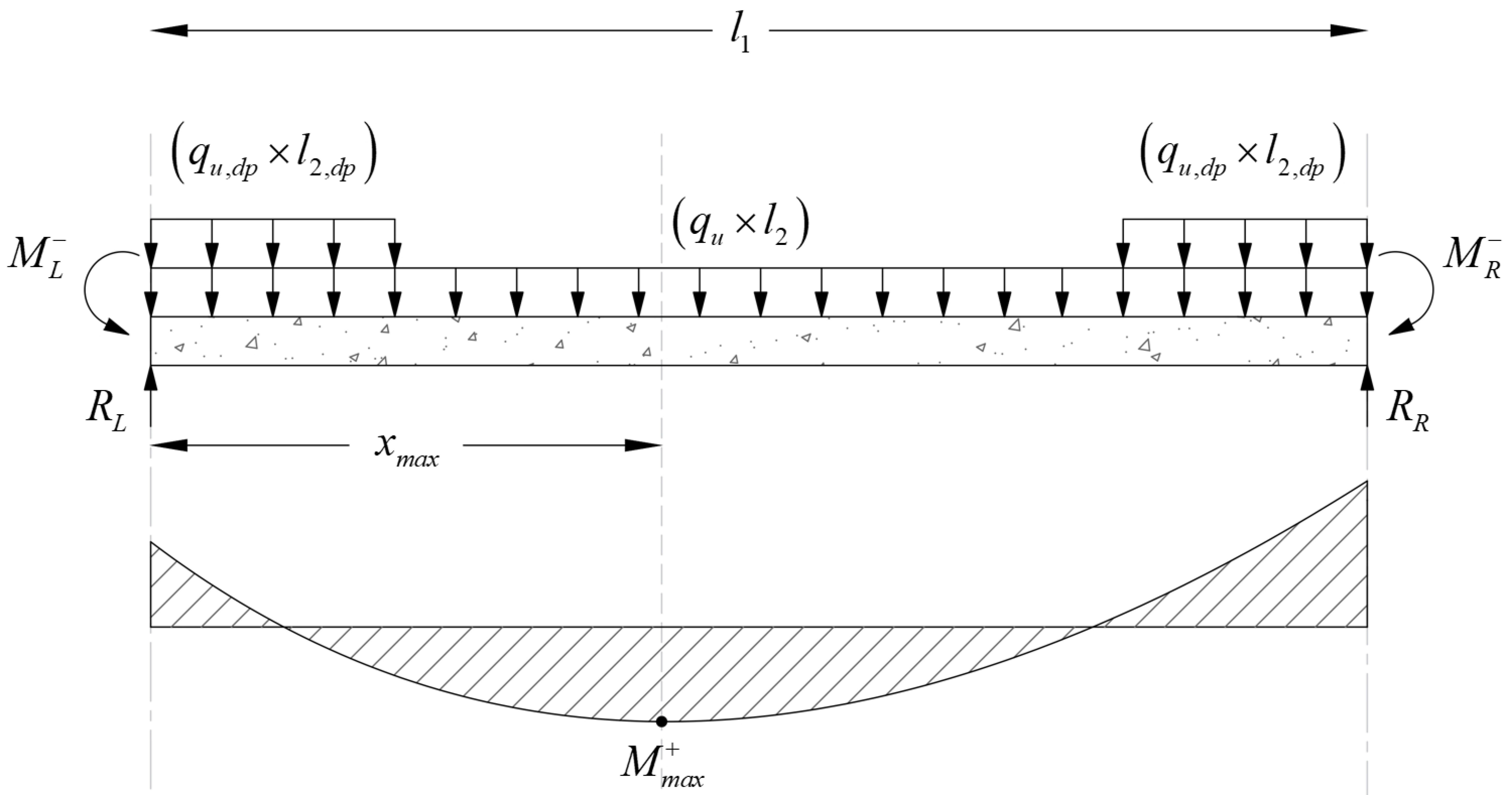
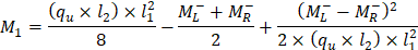
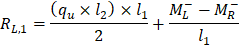
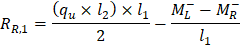
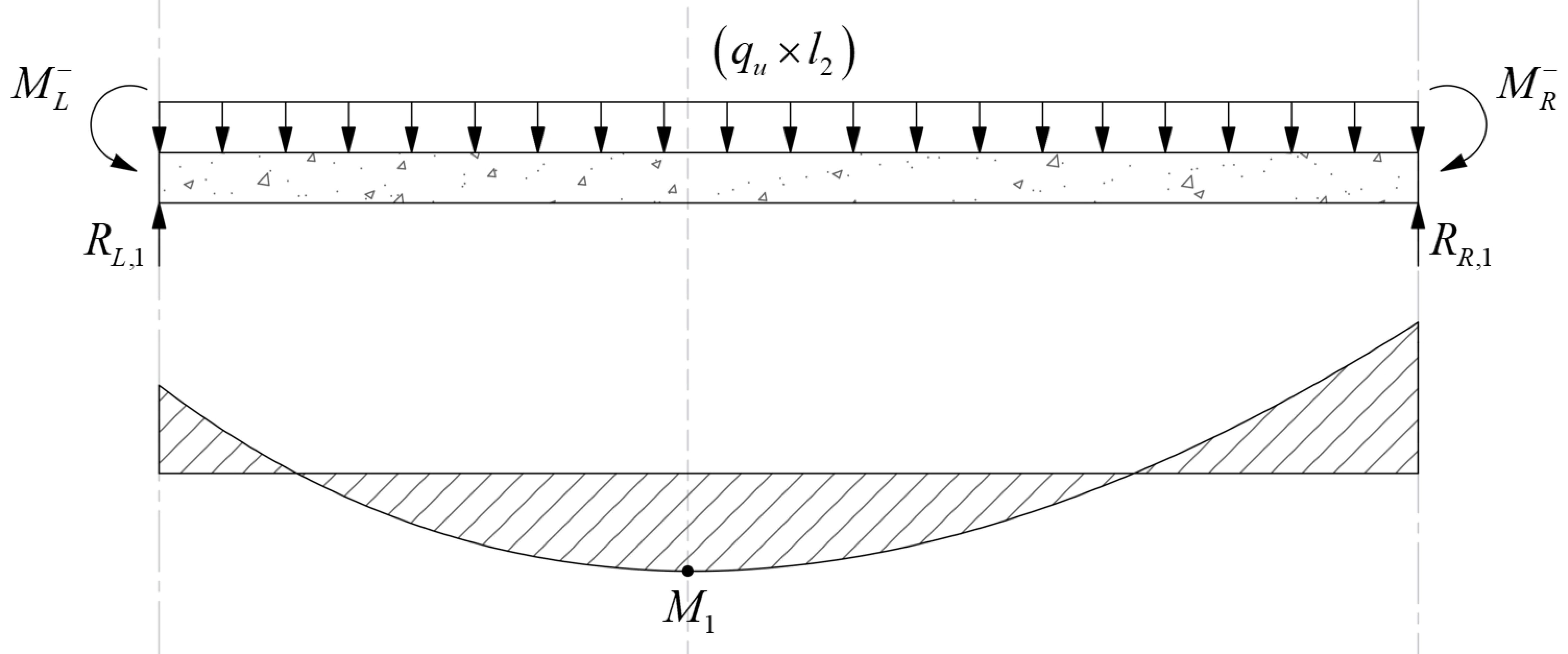
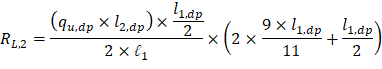
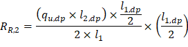
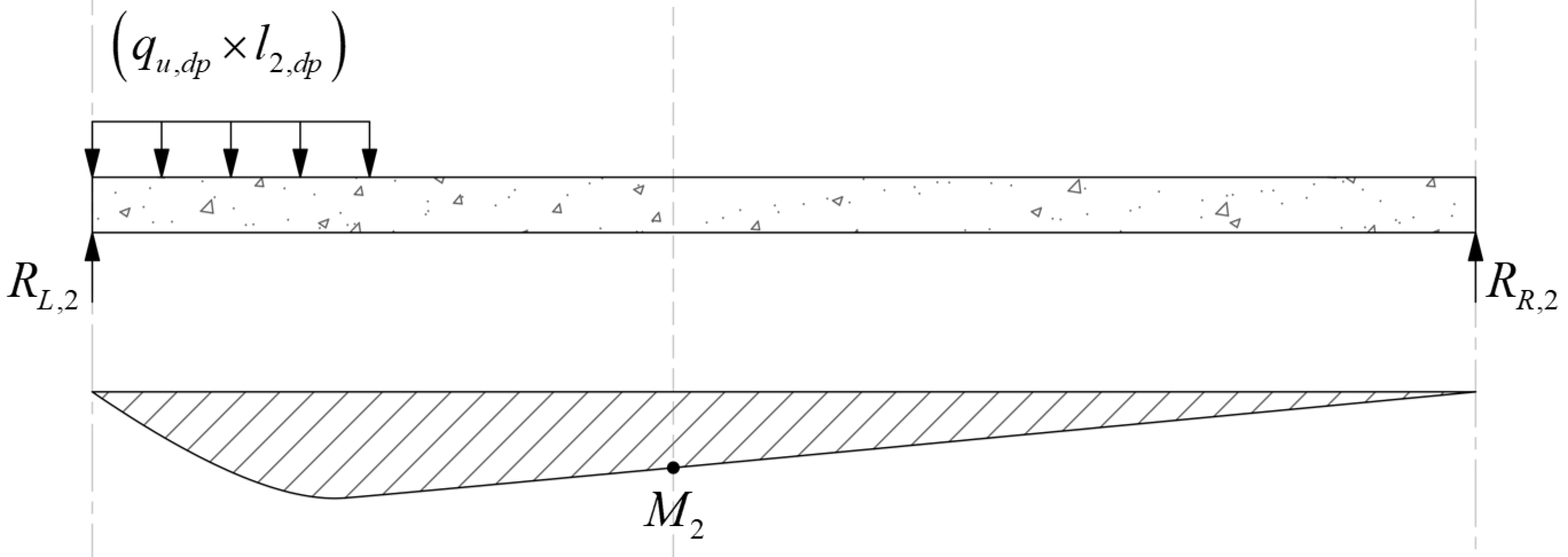
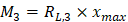
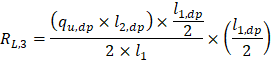


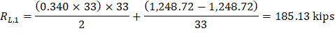
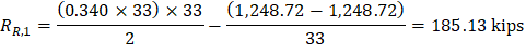
Maximum positive moment in spans 1-2 and 3-4:


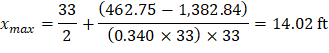
Where:
ML- = 462.75 ft-kips
MR- = 1,382.84 ft-kips
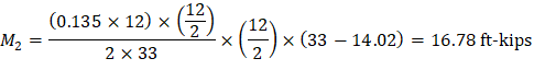
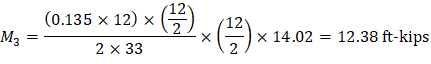
And:


Maximum positive moment in spans 2-3:


Where:
ML- = 1,248.72 ft-kips
MR- = 1,248.72 ft-kips
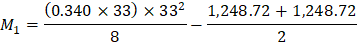

And:


2.1.4. Factored Moments Used for Design
Positive and negative factored moments for the slab system in the direction of analysis are plotted in Figure 18. The negative moments used for design are taken at the faces of supports (rectangle section or equivalent rectangle for circular or polygon sections) but not at distances greater than 0.175 × l1 from the centers of supports.
ACI 318-14 (8.11.6.1)
(use face of support location)
2.1.5. Factored Moments in Slab-Beam Strip
a) Check whether the moments calculated above can take advantage of the reduction permitted by ACI 318-14 (8.11.6.5):
If the slab system analyzed using EFM within the limitations of ACI 318-14 (8.10.2), it is permitted by the ACI code to reduce the calculated moments obtained from EFM in such proportion that the absolute sum of the positive and average negative design moments need not exceed the total static moment Mo given by Equation 8.10.3.2 in the ACI 318-14.
Check Applicability of Direct Design Method:
1) There is a minimum of three continuous spans in each direction. ACI 318-14 (8.10.2.1) 2) Successive span lengths are equal. ACI 318-14 (8.10.2.2) 3) Long-to-Short ratio is 33 / 33 = 1.00 < 2.00. ACI 318-14 (8.10.2.3) 4) Column are not offset. ACI 318-14 (8.10.2.4) 5) Loads are gravity and uniformly distributed with service live-to-dead ratio of 0.67 < 2.00 (Note: The self-weight of the drop panels is not uniformly distributed entirely along the span. However, the variation in load magnitude is small). ACI 318-14 (8.10.2.5 and 6) 6) Check relative stiffness for slab panel. ACI 318-14 (8.10.2.7) Slab system is without beams and this requirement is not applicable.
All limitation of ACI 318-14 (8.10.2) are satisfied and the provisions of ACI 318-14 (8.11.6.5) may be applied:
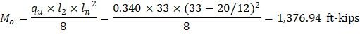
| ACI 318-14 (Eq. 8.10.3.2) |
End spans: | |
Interior span: |
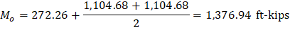
To illustrate proper procedure, the interior span factored moments may be reduced as follows:
Permissible reduction
Adjusted negative design moment = 1,248.72 × 0.885 = 1,104.68 ft-kips
Adjusted positive design moment = 307.76 × 0.885 = 272.26 ft-kips
ACI 318 allows the reduction of the moment values based on the previous procedure. Since the drop panels may cause gravity loads not to be uniform (Check limitation #5 and Figure 18), the moment values obtained from EFM will be used for comparison reasons.
b) Distribute factored moments to column and middle strips:
After the negative and positive moments have been determined for the slab-beam strip, the ACI code permits the distribution of the moments at critical sections to the column strips, beams (if any), and middle strips in accordance with the DDM.
ACI 318-14 (8.11.6.6)
Distribution of factored moments at critical sections is summarized in Table 2.
Slab-beam Strip | Column Strip | Middle Strip | ||||
Moment | Percent | Moment | Percent | Moment | ||
End Span | Exterior Negative | 328.07 | 100 | 328.07 | 0 | 0.00 |
Positive | 668.33 | 60 | 401.00 | 40 | 267.33 | |
Interior Negative | 1,201.69 | 75 | 901.27 | 25 | 300.42 | |
Interior Span | Negative | 1,090.81 | 75 | 818.10 | 25 | 272.70 |
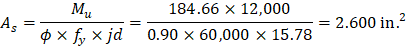
Positive | 307.76 | 60 | 184.66 | 40 | 123.10 | |
2.1.6. Flexural Reinforcement Requirements
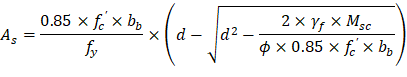
a) Determine flexural reinforcement required for strip moments
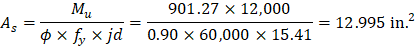
The flexural reinforcement calculation for the column strip of end span - interior negative location is provided below:
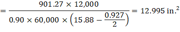
Mu = 901.27 ft-kips
Use d = 15.88 in. (slab with drop panel where h = 17 in.)
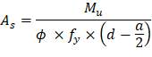
To determine the area of steel, assumptions have to be made whether the section is tension or compression controlled, and regarding the distance between the resultant compression and tension forces along the slab section (jd). In this example, tension-controlled section will be assumed so the reduction factor ϕ is equal to 0.90, and jd will be taken equal to 0.971× d. The assumptions will be verified once the area of steel in finalized.
Assume jd = 0.971 × d = 15.41 in.
Column strip width, | ||
Middle strip width, |
Recalculate ‘a’ for the actual As = 12.995 in.2
| |
| |
|

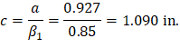

Therefore, the assumption that section is tension-controlled is valid.

Two values of thickness must be considered. The slab thickness in the column strip is 17.00 in. with the drop panel and 8.00 in. for the equivalent slab without the drop panel based on the system weight.
The weighted slab thickness:
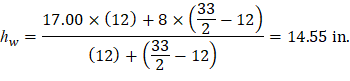
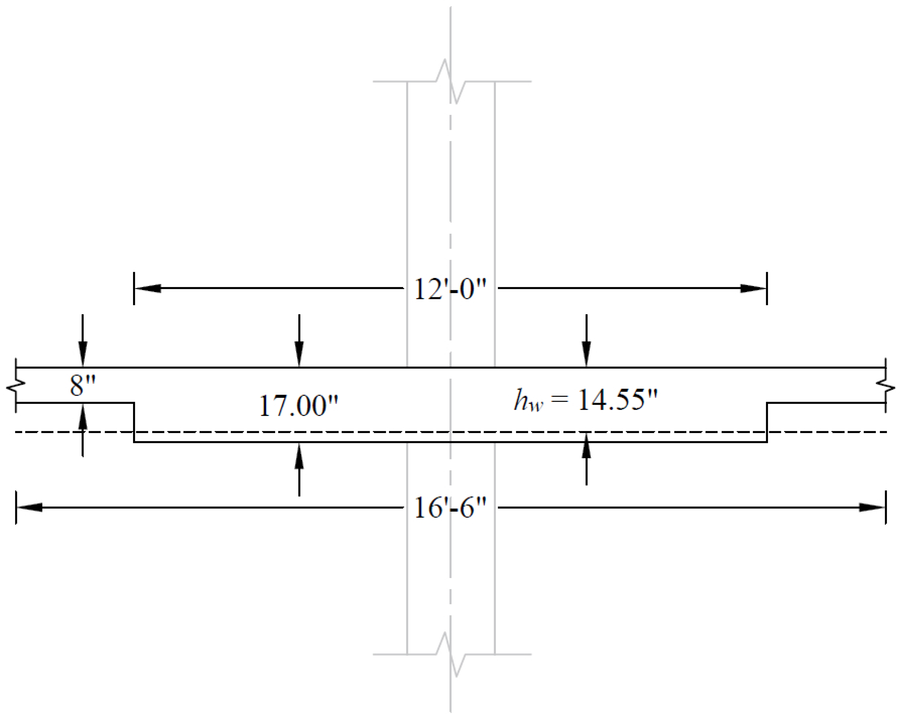
Figure 19 – The Weighted Slab Thickness
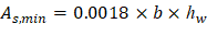
| ACI 318-14 (24.4.3.2) |
| |
| |
Provide 30 - #6 bars with As = 13.20 in.2 and |


The flexural reinforcement calculation for the column strip of interior span - positive location is provided below:
Mu = 184.66 ft-kips
Use d = 15.88 in. (slab with rib where h = 17 in.)
To determine the area of steel, assumptions have to be made whether the section is tension or compression controlled, and regarding the distance between the resultant compression and tension forces along the slab section (jd). In this example, tension-controlled section will be assumed so the reduction factor ϕ is equal to 0.90, and jd will be taken equal to 0.994× d. The assumptions will be verified once the area of steel in finalized.
Assume jd = 0.994 × d = 15.78 in.
Column strip width, | ||
Middle strip width, |
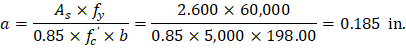
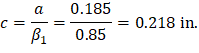
Recalculate ‘a’ for the actual As = 2.600 in.2
| |
| |
|

Therefore, the assumption that section is tension-controlled is valid.
| ACI 318-14 (24.4.3.2) |
| |
| |
Since column strip has 5 ribs → provide 10 – #6 bars (2 bars / rib): | |
|


Based on the procedure outlined above, values for all span locations are given in Table 3.
Table 3 - Required Slab Reinforcement for Flexure [Equivalent Frame Method (EFM)] Mu b d As,req As,min Reinforcement Provided As,Provided (in.2) End Span Column Strip Exterior Negative 328.07 198 15.88 4.641 5.184 14 - #6 * ** 6.16 Positive 401.00 198 15.81 5.709 2.851 10 - #7 (2 bars / rib) 6.00 Interior Negative 901.27 198 15.88 12.995 5.184 30 - #6 13.20 Middle Strip Exterior Negative 0.00 198 15.88 0 5.184 14 - #6 * ** 6.16 Positive 267.33 198 15.88 3.774 2.851 12 - #6 (2 bars / rib) 5.28 Interior Negative 300.42 198 15.88 4.246 5.184 14 - #6 * ** 6.16 Interior Span Column Strip Positive 184.66 198 15.88 2.600 2.851 10 - #6 * (2 bars / rib) 4.40 Middle Strip Positive 123.10 198 15.88 1.730 2.851 12 - #6 * (2 bars / rib) 5.28 ** Design governed by minimum reinforcement. ** Number of bars governed by maximum allowable spacing.
(ft-kips)
(in.)
(in.)
(in.2)
(in.2)
b) Calculate additional slab reinforcement at columns for moment transfer between slab and column by flexure
The factored slab moment resisted by the column (γf × Msc) shall be assumed to be transferred by flexure. Concentration of reinforcement over the column by closer spacing or additional reinforcement shall be used to resist this moment. The fraction of slab moment not calculated to be resisted by flexure shall be assumed to be resisted by eccentricity of shear.
ACI 318-14 (8.4.2.3)
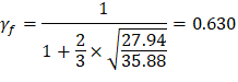
Portion of the unbalanced moment transferred by flexure is γf × Msc | ACI 318-14 (8.4.2.3.1) |
Where: | |
ACI 318-14 (8.4.2.3.2) |
• b1 | = | Dimension of the critical section bo measured in the direction of the span for which moments are determined in ACI 318, Chapter 8 (see Figure 20). | |
• b2 | = | Dimension of the critical section bo measured in the direction perpendicular to b1 in ACI 318, Chapter 8 (see Figure 20). | |
• bb | = | Effective slab width = c2 + 3 × h | ACI 318-14 (8.4.2.3.3) |
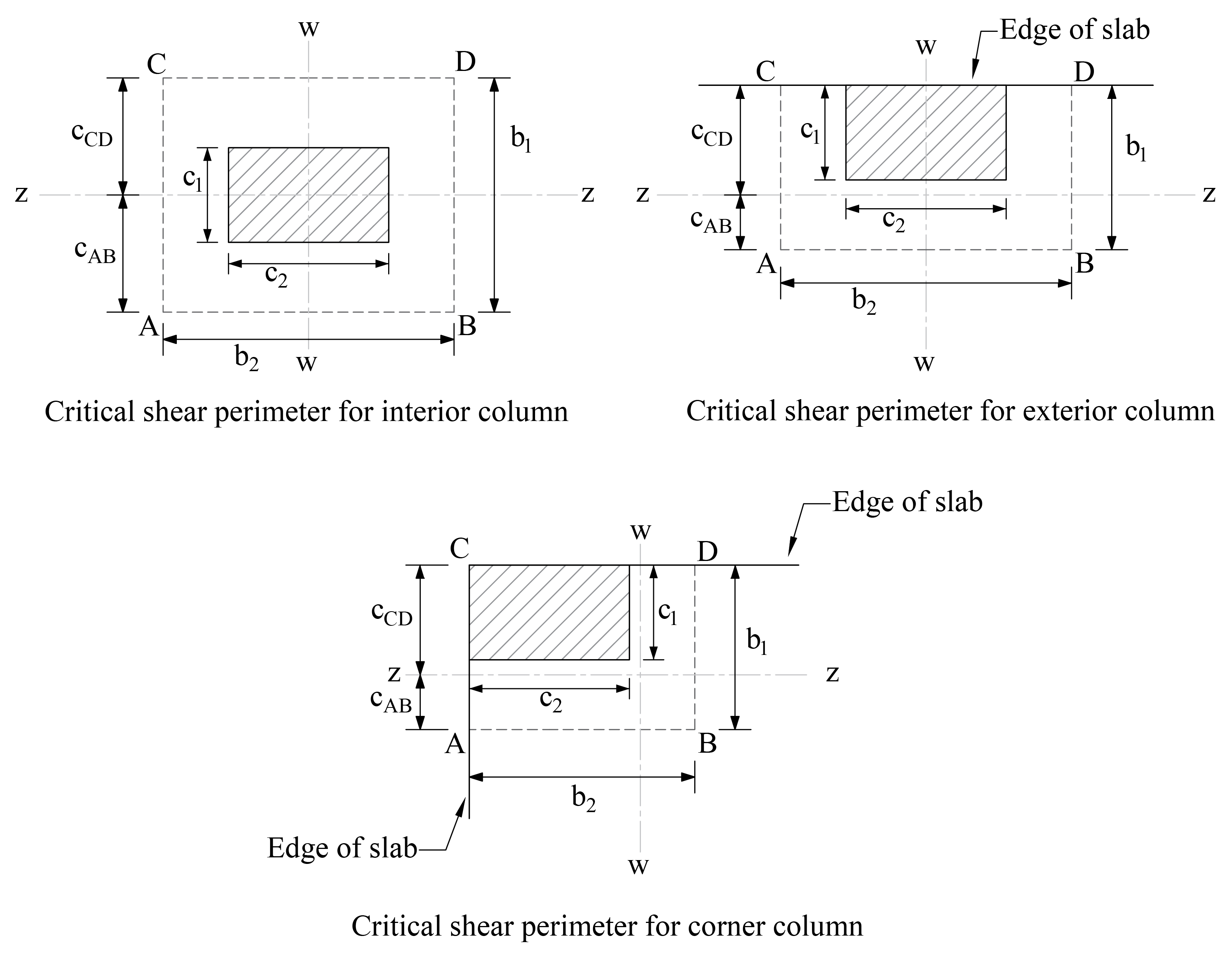
Figure 20 – Critical Shear Perimeters for Columns
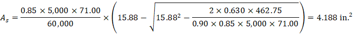
Mu = 462.75 ft-kips | As(prov) = 6.16 in.2 |
|
|
|
|
| |
| |
However, the area of steel provided to resist the flexural moment within the effective slab width bb: | |
| |
Then, the required additional reinforcement at exterior column for moment transfer between slab and column: | |
| |
Provide 5- #6 additional bars with As = 2.20 in.2 | |


Based on the procedure outlined above, values for all supports are given in Table 4.
Table 4 - Additional Slab Reinforcement required for moment transfer between slab and column (EFM) | |||||||||
Msc* (ft-kips) | γf | γf Msc (ft-kips) | Effective slab width, bb (in.) | d (in.) | As req’d within | As prov. For flexure | Add’l Reinf. | ||
End Span | |||||||||
Column Strip | Exterior Negative | 462.75 | 0.630 | 291.35 | 71.00 | 15.88 | 4.188 | 2.209 | 5-#6 |
Interior Negative | 134.12 | 0.600 | 80.47 | 71.00 | 15.88 | 2.029 | 4.733 | - | |
* Msc is taken at the centerline of the support in Equivalent Frame Method solution. | |||||||||
2.1.7. Factored Moments in Columns
The unbalanced moment from the slab-beams at the supports of the equivalent frame are distributed to the support columns above and below the slab-beam in proportion to the relative stiffness of the support columns. Referring to Figure 18, the unbalanced moment at the exterior and interior joints are:
Exterior Joint = + 462.75 ft-kips
Joint 2 = - 1,382.84 + 1,248.72 = -134.12 ft-kips
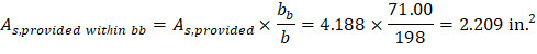
The stiffness and carry-over factors of the actual columns and the distribution of the unbalanced slab moments (Msc) to the exterior and interior columns are shown in Figure 21.
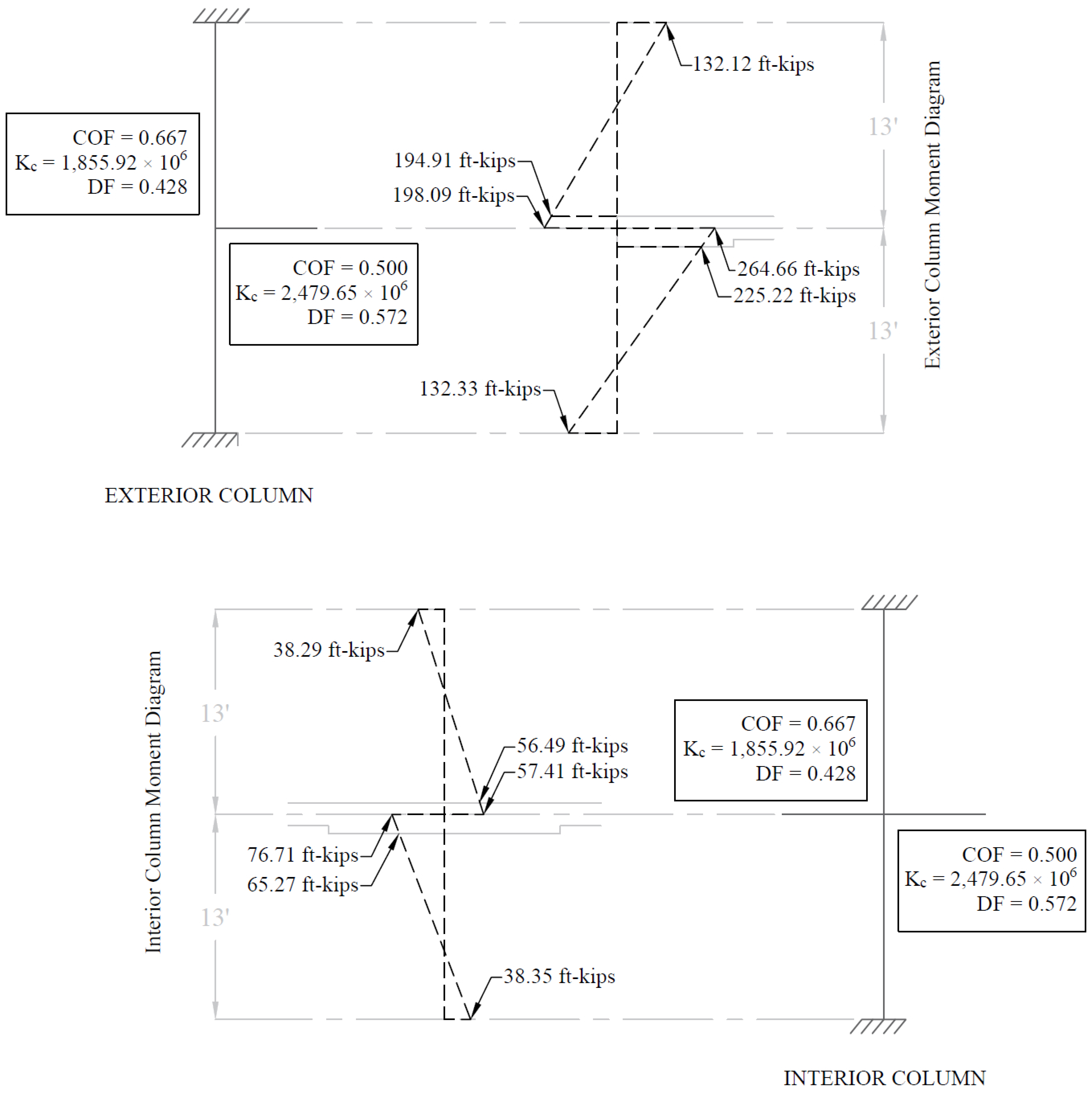
Figure 21 – Column Moments (Unbalanced Moments from Slab-Beam)
For Top column (Above): For Bottom column (Below): Mcol,Exterior = 194.91 ft-kips Mcol,Exterior = 225.22 ft-kips Mcol,Interior = 56.49 ft-kips Mcol,Interior = 65.27 ft-kips
The moments determined above are combined with the factored axial loads (for each story) and factored moments in the transverse direction for design of column sections. The moment values at the face of interior, exterior, and corner columns from the unbalanced moment values are shown in the Table 5.
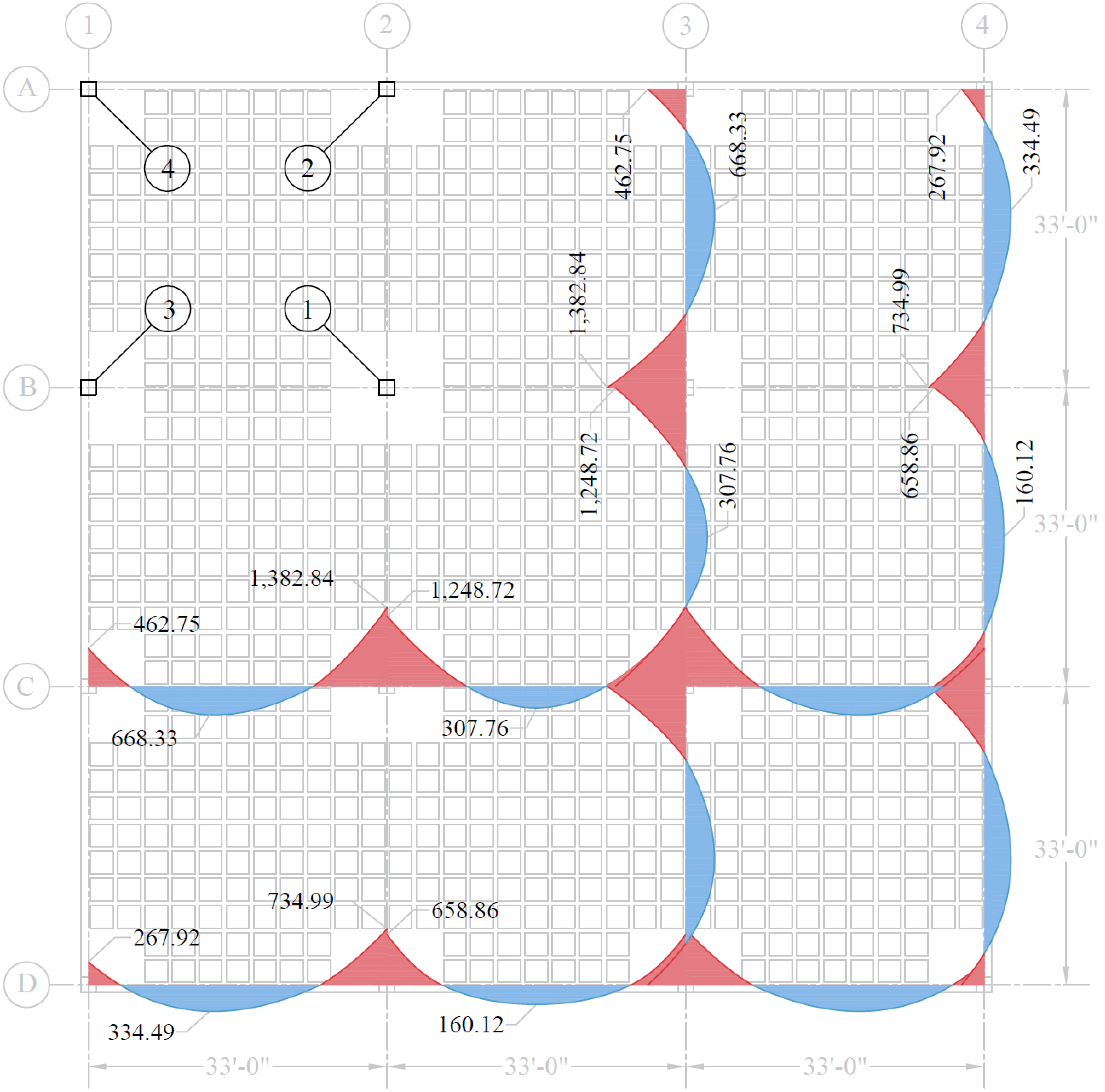
Figure 22 – Moment Diagrams (kips-ft)
Column Location | |||
Interior | Exterior | Corner | |
Mux | 65.27 | 225.22 | 225.22 |
Muy | 65.27 | 65.27 | 225.22 |