2.1. Factored Load and Reactions
Girder Self-Weight: | ||
Dead Load: | ||
Live Load: | ||
Factored Load: | ACI 318-14 (Eq. 5.3.1b) | |
(at point C) | ||
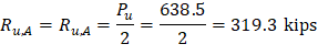
Reactions: |
|
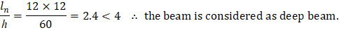
The beam is considered deep if | ACI 318-14 (Eq. 9.9.1.1) | |
| ||
2.3. Maximum Shear Capacity of the Cross Section
ACI 318-14 (9.9.1.1) | ||
O.K. | ||
Several strut-and-tie models can be selected. The following model is being selected in order to be consistent with the reference. Alternative truss or STMs are discussed later in this document.
Assume that the nodes coincide with the centerline of the column and supports, and are located 5 in. from the upper or lower edge of the beam as shown in the following figure. This strut-and-tie model consists of two struts (A-C and B-C), one tie (A-B), and three nodes (A, B, and C). In addition, columns at A and B act as struts representing reactions. The vertical strut located in the upper column at the top of Node C represents the applied load.

Figure 8 - Preliminary Truss Model Layout
Length of diagonal struts: | |||
Length of the horizontal tie: | |||
The force in diagonal struts: | |||
The force in horizontal tie: | |||
The angle between the diagonal struts and horizontal tie: | |||
| O.K. | ACI 318-14 (23.2.7) | |

2.5. Effective Concrete Strength for the Struts
The effective concrete strength for the struts in this STM is calculated assuming that reinforcement is provided per to resist splitting forces. | ACI 318-14 (23.5.1) |
For the “bottle-shaped” struts A-C and B-C: | |
| ACI 318-14 (Eq. 23.4.3) |
Where: | |
βs = 0.75 | ACI 318-14 (Table 23.4.3(b)) |
This effective compressive strength cannot exceed the strength of the nodes at both ends of the strut. | ACI 318-14 (23.4.1) |
The vertical struts in columns A, B, and C can be assumed to have uniform cross-sectional area throughout their length. | |
| ACI 318-14 (Eq. 23.4.3) |
Where: | |
βs = 1.0 for prismatic struts | ACI 318-14 (Table 23.4.3(a)) |


2.6. Effective Concrete Strength for the Nodal Zones
Nodal Zone C is bounded by three struts. Thus, this is a C-C-C nodal zone where: | |
βn = 1.0 | ACI 318-14 (Table 23.9.2(a)) |
| ACI 318-14 (Eq. 23.9.2) |
Nodal Zones A and B are bounded by two struts and a tie. Thus, this is a C-C-T nodal zone where: | |
βn = 0.80 | ACI 318-14 (Table 23.9.2(b)) |
| ACI 318-14 (Eq. 23.9.2) |


2.7. Strength and Truss Geometry Checks for the STM Nodal Zones
Node C: | |
Assume that a hydrostatic nodal zone is formed at Node C. This means that the faces of the nodal zone are perpendicular to the axis of the respective struts, and that the stresses are identical on all faces. | |
To satisfy the strength criteria for all three struts and the node, the minimum nodal face dimension is determined based on the least strength value: | |
Thus, governed by the bottle-shaped diagonal struts. The same strength value will be used for Nodes A and B as well. | |
The strength checks for all components of the strut and tie model are based on | |
| ACI 318-14 (23.3.1) |
Where ϕ = 0.75 | ACI 318-14 (Table 21.2.1(g)) |
The length of the horizontal face of Nodal Zone C is calculated as: | |
Notice that the horizontal face of Nodal Zone C is less than the column width (20 in.). | |
The length of the other faces, perpendicular to the diagonal struts, can be obtained from proportionality: | |
The center of the nodal zone is at 4.0 in. from the top of the beam (as shown in the following figure), which is very close to the assumed 5 in. | |
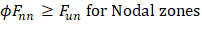

Figure 9 - Geometry of Node C
Node A and B: |
The same strength value used for node C will be used for Nodes A and B as well. |
fce = 2,550 psi |
The length of the vertical face of Nodal Zone A and B is calculated as: |
The center of the tie is located 13.4/2 = 6.7 in. from the bottom of the beam. |
This is reasonably close to the 5 in. originally assumed, so no further iteration is warranted. |
The length of the horizontal face of Nodal Zone A and B: |
The following figure shows the geometry of Nodes A based on the calculations shown above (note that the geometry of Node B is identical to Node A). |

Figure 10 - Geometry of Node C
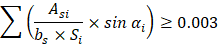
2.8. Vertical and Horizontal Reinforcement to Resist Splitting of STM Diagonal Struts
For f′c not greater than 6,000 psi, the requirement of ACI 318-14 (23.5.1) shall be permitted to be satisfied by the axis of the strut being crossed by layers of reinforcement that satisfy ACI 318-14 (Eq. 23.5.3). | |
f′c = 4,000 psi ≤ 6,000 psi O.K. | ACI 318-14 (23.5.3) |
The angle between the vertical ties and the struts (α2 is calculated in section 2.4): | |
ACI 318-14 (R23.5.1) | |

Figure 11 - Reinforcement Crossing a Strut (ACI 318-14)
For vertical reinforcement, try two overlapping #4 stirrups @ 11 in. o.c. to accommodate the longitudinal tie reinforcement designed in the next section. | |
For horizontal reinforcement, try #5 horizontal bars @ 11 in. o.c. on each side face. | |
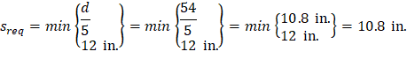
The 11 in. spacing is calculated as follows: | |
| ACI 318-14 (9.9.4.3) |
Based on the selected reinforcement: | |
| ACI 318-14 (23.5.3) |
O.K.
Both directions of shear reinforcement have to satisfy deep beams requirements for this transfer girder as shown below:
ACI 318-14 (Eq. 9.9.3.1(a)) |
O.K.
ACI 318-14 (Eq. 9.9.3.1(b)) |
O.K.
2.9. Horizontal Reinforcement for Tie Connecting Nodes A and B
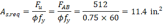 à Select 16 #8 (As = 12.64 in.2)
These bars must be properly anchored. The anchorage length (lanc) is to be measured from the point where the tie exits the extended nodal zone as shown in the following figure:

Figure 12 - Development of Tie Reinforcement Within the Extended Nodal Zone
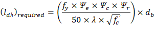
Required development length for straight bars in tension can be estimated using the following equation:
N.G. | ACI 318-14 (R25.4.2) | |
Use #8 bars with a standard 90º hook: | ||
| ACI 318-14 (25.4.3.1(a)) | |
O.K. | ||
Type of standard hook | Bar size | Minimum inside bend diameter, in. | Straight extension lext, in. | Type of standard hook | |
90-degree hook | No. 3 through No. 5 | 4db | Greater of 6db and 3 in. |
| |
No. 6 through No. 8 | 6db | 12db | |||

Figure 13 - Standard Hook Geometry for 90º Hook (Table 25.3.2 ACI 318-14)
The following are notes related to the development length of the horizontal reinforcement for the tie: | |
1) The 90o hooks will be enclosed within the column reinforcement that extends in the transfer girder. | |
2) By providing adequate cover and transverse confinement, the development length of the standard hook could be reduced by modifiers. | ACI 318-14 (25.4.3.1(a)) |
3) Less congested reinforcement schemes can be devised with the use of head bars, reinforcing steel welded to bearing plates, or with the use of prestressing steel. | ACI 318-14 (25.4.4) |

Figure 14 - Detail of STM Tie Reinforcement
The discrepancy in the vertical location of the nodes results in a negligible (about 1.5 percent) difference in the truss forces. Thus, another iteration is not warranted.
There are several alternative strut-and-tie models that could have been devised for this problem. An alternative truss layout/STM is illustrated in the following figure. It has the advantage that the force in the bottom chord varies between nodes, instead of being constant between supports. Further, the truss posts carry truss forces, instead of providing vertical reinforcement just for crack control.
ACI 318-14 (23.5.3)
Finally, the diagonals are steeper, therefore the diagonal compression and the bottom chord forces are reduced. The optimum idealized truss/STM is one that requires the least amount of reinforcement.

Figure 15 - Alternative Strut-and-Tie Model