6. Pure Bending
This corresponds to the case where the nominal axial load capacity, Pn, is equal to zero. The following show the general iterative procedure to calculate the moment capacity of the irregular wall section at this control point, all the calculated values are shown in the next Table.
6.1. c, a, and strains in the reinforcement
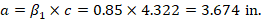
Try c = 4.322 in.
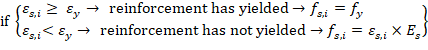
Where c is the distance from the fiber of maximum compressive strain to the neutral axis. ACI 318-19 (22.2.2.4.2)
 ACI 318-19 (22.2.2.4.1)
Where:
 ACI 318-19 (Table 22.2.2.4.3)
 ACI 318-19 (22.2.2.1)

 ACI 318-19 (Table 21.2.2)
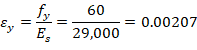
The maximum tensile strain calculated above is significantly higher than the yield strain and indicates the section is very lightly reinforced. Increasing the steel area will result in lower maximum strain and increase the moment capacity.
6.2. Forces in the concrete and steel
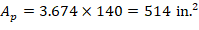
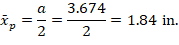
Since a = 3.674 in. < h1 = 14 in., the area and centroid of the concrete equivalent block can be found as follows:
 ACI 318-19 (22.2.2.4.1)
If the reinforcement layer is located within the depth of the equivalent rectangular stress block (a), it is necessary to subtract 0.85fc’ from fs,i before computing Fs,i since the area of the reinforcement in this layer has been included in the area used to compute Cc.
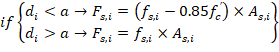
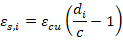
The force developed in the reinforcement layer (Fs,i) is considered as compression force (Cs,i) if the effective depth of this steel layer (di) is less than c (the distance from the fiber of maximum compressive strain to the neutral axis), otherwise it is considered as tension force (Ts,i).
6.3. ϕPn and ϕMn
Using values from the next Table:
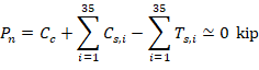
The assumption that c = 4.322 in. is correct.
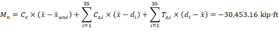

Table 8 - Axial and Moment Capacity for the Sixth Control Point
|
Layer
| As/bar, in2
| # of bars, in
| d, in
| εs, in./in.
| fs,i, kip
| Cs,i,kip
| Ts,i, kip
| Mn,i, kip-ft
|
1
| 0.79
| 12
| 2.5
| -0.00126
| 36.7
| -315.5
| 0.0
| -4,146.1
|
2
| 0.79
| 12
| 11.5
| 0.00498
| 60.0
| 0.0
| 568.8
| 7,049.3
|
3
| 0.31
| 2
| 20.0
| 0.01088
| 60.0
| 0.0
| 37.2
| 434.7
|
4
| 0.31
| 2
| 32.0
| 0.01921
| 60.0
| 0.0
| 37.2
| 397.5
|
5
| 0.31
| 2
| 44.0
| 0.02754
| 60.0
| 0.0
| 37.2
| 360.3
|
6
| 0.31
| 2
| 56.0
| 0.03587
| 60.0
| 0.0
| 37.2
| 323.1
|
7
| 0.31
| 2
| 68.0
| 0.0442
| 60.0
| 0.0
| 37.2
| 285.9
|
8
| 0.31
| 2
| 80.0
| 0.05253
| 60.0
| 0.0
| 37.2
| 248.7
|
9
| 0.31
| 2
| 92.0
| 0.06086
| 60.0
| 0.0
| 37.2
| 211.5
|
10
| 0.31
| 2
| 104.0
| 0.06919
| 60.0
| 0.0
| 37.2
| 174.3
|
11
| 0.31
| 2
| 116.0
| 0.07752
| 60.0
| 0.0
| 37.2
| 137.1
|
12
| 0.31
| 2
| 128.0
| 0.08585
| 60.0
| 0.0
| 37.2
| 99.9
|
13
| 0.31
| 2
| 140.0
| 0.09418
| 60.0
| 0.0
| 37.2
| 62.7
|
14
| 0.31
| 2
| 152.0
| 0.10251
| 60.0
| 0.0
| 37.2
| 25.5
|
15
| 0.31
| 2
| 164.0
| 0.11084
| 60.0
| 0.0
| 37.2
| -11.7
|
16
| 0.31
| 2
| 176.0
| 0.11917
| 60.0
| 0.0
| 37.2
| -48.9
|
17
| 0.31
| 2
| 188.0
| 0.1275
| 60.0
| 0.0
| 37.2
| -86.1
|
18
| 0.31
| 2
| 200.0
| 0.13582
| 60.0
| 0.0
| 37.2
| -123.3
|
19
| 0.31
| 2
| 212.0
| 0.14415
| 60.0
| 0.0
| 37.2
| -160.5
|
20
| 0.31
| 2
| 224.0
| 0.15248
| 60.0
| 0.0
| 37.2
| -197.7
|
21
| 0.31
| 2
| 236.0
| 0.16081
| 60.0
| 0.0
| 37.2
| -234.9
|
22
| 0.31
| 2
| 248.0
| 0.16914
| 60.0
| 0.0
| 37.2
| -272.1
|
23
| 0.31
| 2
| 260.0
| 0.17747
| 60.0
| 0.0
| 37.2
| -309.3
|
24
| 0.31
| 2
| 272.0
| 0.1858
| 60.0
| 0.0
| 37.2
| -346.5
|
25
| 0.31
| 2
| 284.0
| 0.19413
| 60.0
| 0.0
| 37.2
| -383.7
|
26
| 0.31
| 2
| 296.0
| 0.20246
| 60.0
| 0.0
| 37.2
| -420.9
|
27
| 0.31
| 2
| 308.0
| 0.21079
| 60.0
| 0.0
| 37.2
| -458.1
|
28
| 0.31
| 2
| 320.0
| 0.21912
| 60.0
| 0.0
| 37.2
| -495.3
|
29
| 0.31
| 2
| 332.0
| 0.22745
| 60.0
| 0.0
| 37.2
| -532.5
|
30
| 0.31
| 2
| 344.0
| 0.23578
| 60.0
| 0.0
| 37.2
| -569.7
|
31
| 0.31
| 2
| 356.0
| 0.24411
| 60.0
| 0.0
| 37.2
| -606.9
|
32
| 0.31
| 2
| 368.0
| 0.25244
| 60.0
| 0.0
| 37.2
| -644.1
|
33
| 0.79
| 3
| 376.5
| 0.25834
| 60.0
| 0.0
| 142.2
| -2,562.9
|
34
| 0.79
| 2
| 386.0
| 0.26493
| 60.0
| 0.0
| 94.8
| -1,783.7
|
35
| 0.79
| 3
| 395.5
| 0.27153
| 60.0
| 0.0
| 142.2
| -2,788.1
|
Concrete
| ---
| x̅p =
| 1.84
| ---
| ---
| -1,748.7
| 0.0
| -23,079.9
|
|
|
|
|
| Pn, kip
| 0.0
| Mn, kip-ft
| -30,453
|