Control Points (Moment Rotation about the Positive Y-Axis)
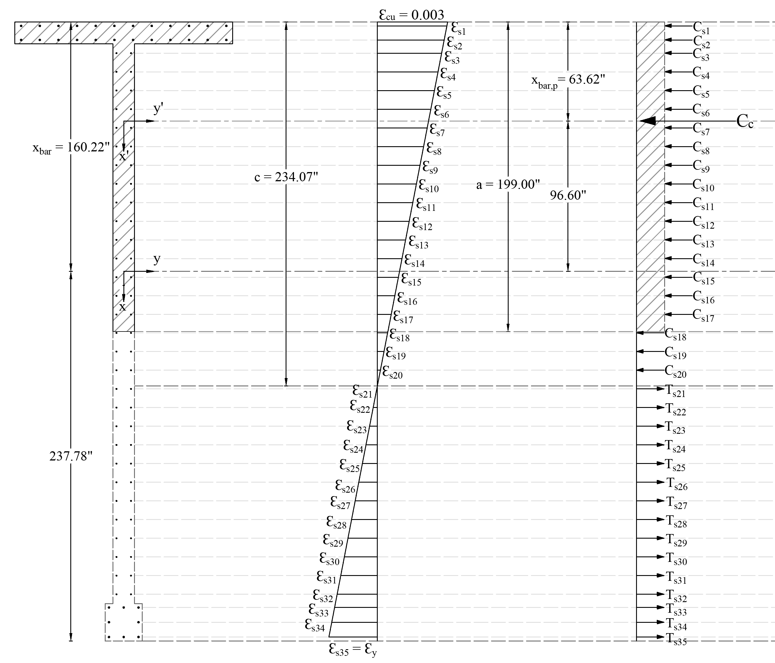
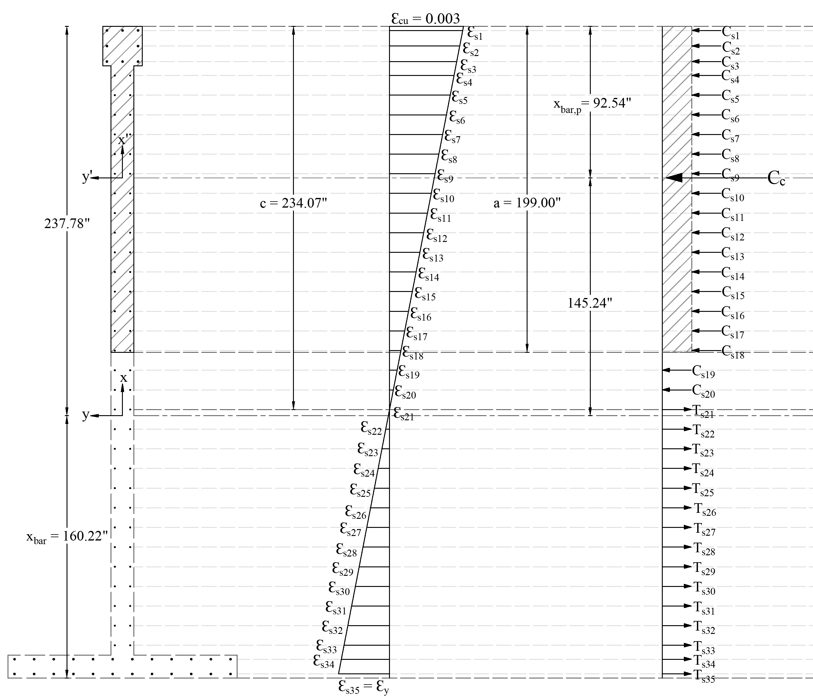
Since the wall section is not symmetrical (irregular) about the y-axis, the rotation of moment about the negative or positive y-axis results in different values for the control points (except for the maximum compression and maximum tension control points, these two points are the same for both cases). The following table shows the control points (when the moment is applied about the positive y-axis) obtained using the same procedure described above for the case when the moment is applied about the negative y-axis. The following two figures show the differences in the strain and force distribution for both cases for the same control point.
Figure 7 - Strains and Forces Distribution (fs = fy) (Moment about Negative Y-Axis)
Figure 8 - Strains and Forces Distribution (fs = fy) (Moment about Positive Y-Axis)

