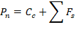
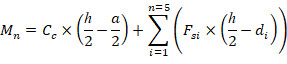
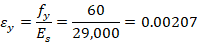
3. Bar Stress Near Tension Face Equal to 0.5 fy, (fs = 0.5 fy)

07 Bar Stresss Near Tension Face Equal to 0.5fy

Figure 5 - Strains, Forces, and Moment Arms (fs = 0.5 fy)

For Concrete:


    ACI 318-19 (Table 21.2.2)

    ACI 318-19 (22.2.2.1)


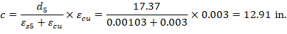
Where c is the distance from the fiber of maximum compressive strain to the neutral axis.    ACI 318-19 (22.2.2.4.2)

    ACI 318-19 (22.2.2.4.1)

Where:

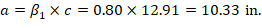
a = Depth of equivalent rectangular stress block

    ACI 318-19 (Table 22.2.2.4.3)

(Compression)    ACI 318-19 (22.2.2.4.1)

Where:


08 Section

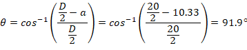
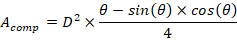
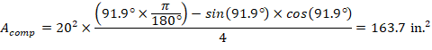
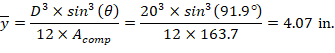
Figure 6 - Cracked Column Section Properties (fs = 0.5 fy)

For Reinforcement:


The area of the reinforcement in this layer is not included in the area (ab) used to compute Cc. As a result, it is NOT necessary to subtract 0.85fc from fs5 before computing Fs5:

(Tension)


The area of the reinforcement in this layer is not included in the area (ab) used to compute Cc. As a result, it is NOT necessary to subtract 0.85fc from fs4 before computing Fs4:

(Tension)

The same procedure shown above can be repeated to calculate the forces in the remaining reinforcement layers, results are summarized in the following table:

Table 3 - Strains and internal force resultants (fs = 0.5 fy)

Layer

d, in

ε, in./in.

fs, psi

Fs, kip

Cc, kip

Moment arm (r), in.

Moment, kip-ft

Concrete

---

0.00300

---

---

695.63

4.07

235.73

1

2.64

0.00239

60000

70.80*

---

7.37

43.46

2

4.79

0.00189

54712

128.17*

---

5.21

55.62

3

10.00

0.00068

19623

39.05*

---

0.00

0.00

4

15.21

-0.00053

-15465

-39.28

---

-5.21

17.05

5

17.37

-0.00103

-30000

-38.1

---

-7.37

23.38

Axial Force and Bending Moment

Pn, kip

856.27

Mn, kip-ft

375.24

ϕPn, kip

642.20

ϕMn, kip-ft

281.43

* The area of the reinforcement in this layer has been included in the area (ab) used to compute Cc. As a result, 0.85fc is subtracted from fs in the computation of Fs.


Where:


(+) = Compression

(-) = Tension


(+) = Counter Clockwise

(-) = Clockwise