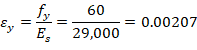
4. Bar Stress Near Tension Face Equal to fy, (fs = fy)
Figure 7 - Strains, Forces, and Moment Arms (fs = fy)
This strain distribution is called the balanced failure case and the compression-controlled strain limit. It marks the change from compression failures originating by crushing of the compression surface of the section, to tension failures initiated by yield of longitudinal reinforcement. It also marks the start of the transition zone for ϕ for columns in which ϕ increases from 0.75 for spiral columns (or 0.65 for tied columns) up to 0.90.


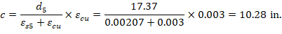
Where c is the distance from the fiber of maximum compressive strain to the neutral axis. ACI 318-19 (22.2.2.4.2)
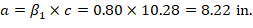
a = Depth of equivalent rectangular stress block

 (Compression) ACI 318-19 (22.2.2.4.1)
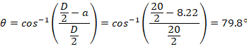
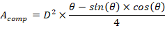
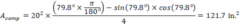
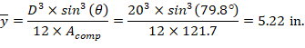

Figure 8 - Cracked Column Section Properties (fs = fy)

The area of the reinforcement in this layer is not included in the area (ab) used to compute Cc. As a result, it is NOT necessary to subtract 0.85fc’ from fs5 before computing Fs5:


The area of the reinforcement in this layer is not included in the area (ab) used to compute Cc. As a result, it is NOT necessary to subtract 0.85fc’ from fs4 before computing Fs4:

The same procedure shown above can be repeated to calculate the forces in the remaining reinforcement layers, results are summarized in the following table:
* The area of the reinforcement in this layer has been included in the area (ab) used to compute Cc. As a result, 0.85fc’ is subtracted from fs in the computation of Fs.