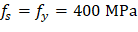
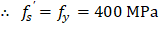
4. Bar Stress Near Tension Face of Member Equal to fy, (fs = - fy)
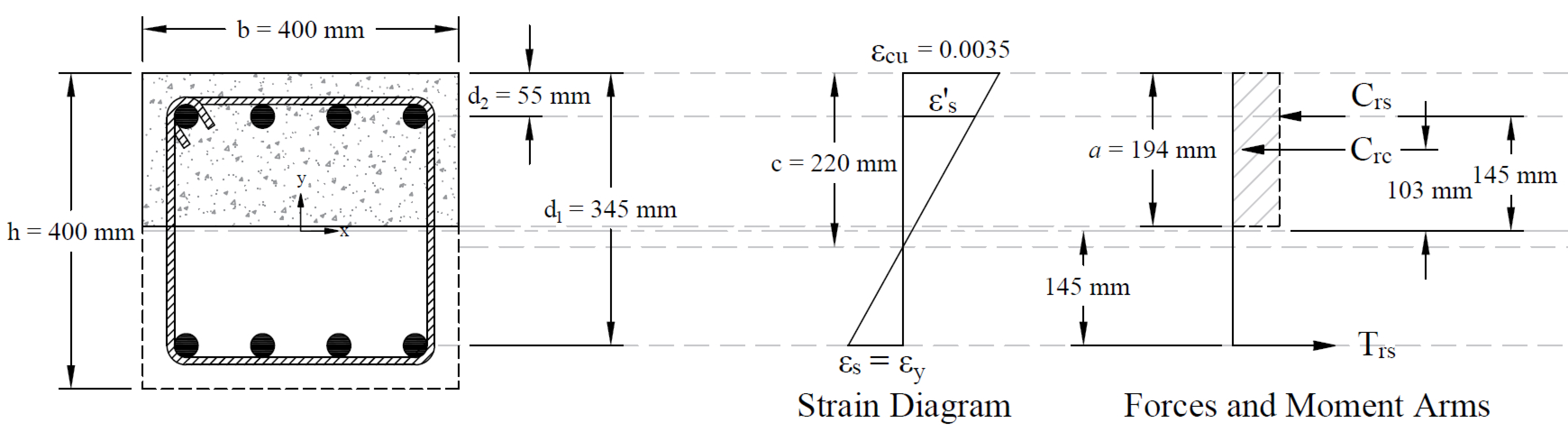
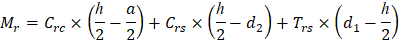
Figure 5 - Strains, Forces, and Moment Arms (fs = - fy)
This strain distribution is called the balanced failure case and the compression-controlled strain limit. It marks the change from compression failures originating by crushing of the compression surface of the section, to tension failures initiated by yield of longitudinal reinforcement.
4.1. c, a, and strains in the reinforcement
| |
| |
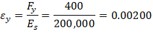
| CSA A23.3-19 (8.4.2) |
| CSA A23.3-19 (8.4.3(a)) |
| CSA A23.3-19 (10.1.3) |
| |
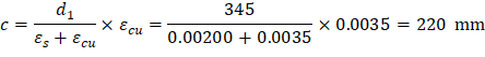
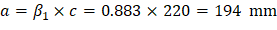
Where c is depth of the neutral axis measured from the compression edge of the column section. | CSA A23.3-19 (3.2) |
| CSA A23.3-19 (10.1.7) |
Where: | |
a = Depth of equivalent rectangular stress block | CSA A23.3-19 (3.2) |
| CSA A23.3-19 (Equation 10.2) |
| |


4.2. Forces in the concrete and steel
| CSA A23.3-19 (10.1.7) |
| |
| |
| |
| |
The area of the reinforcement in this layer has been included in the area (ab) used to compute Crc. As a result, it is necessary to subtract α1ϕcfc’ from ϕsfs’ before computing Crs: | |
| |


| |
| |
|