The analysis of the reinforced concrete section performed by spColumn conforms to the provisions of the Strength Design Method and Unified Design Provisions with all conditions of strength satisfying the applicable conditions of equilibrium and strain compatibility.
In the calculation shown above a P-M interaction diagram was generated with moments about the X-Axis (Uniaxial bending). Since the reinforcement in the section is not symmetrical, a different P-M interaction diagram is needed for the other orthogonal direction about the Y-Axis (See the following Figure for the case where fs = fy).
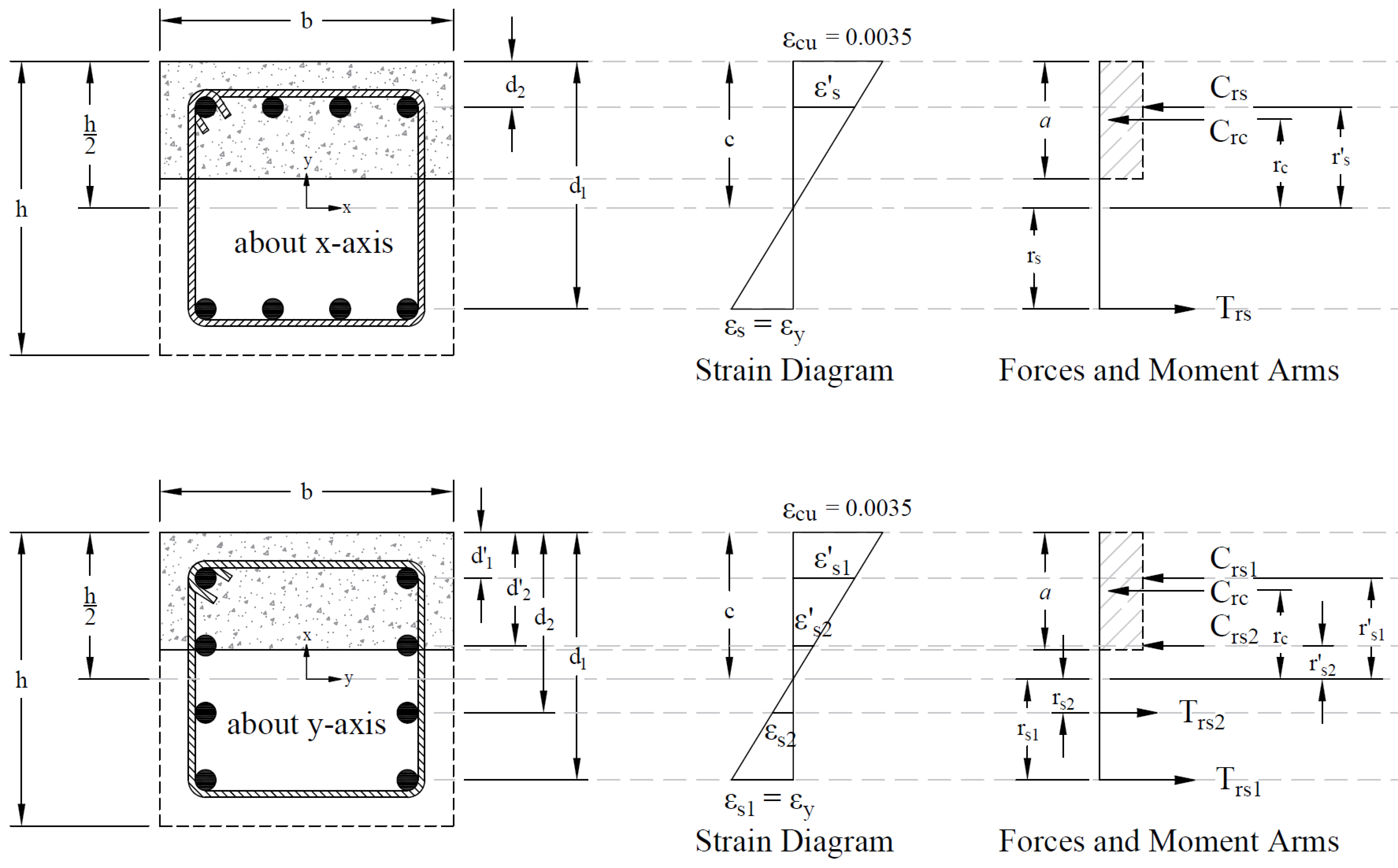
Figure 11 - Strains, Forces, and Moment Arms (fs = - fy Moments About x- and y-axis)
When running about the Y-Axis, we have 2 bars in 4 layers instead of 4 bars in just 2 layers (about X-Axis) resulting in a completely different interaction diagram as shown in the following Figure. Further differences in the interaction diagram in both directions can result if the column cross section geometry is irregular.
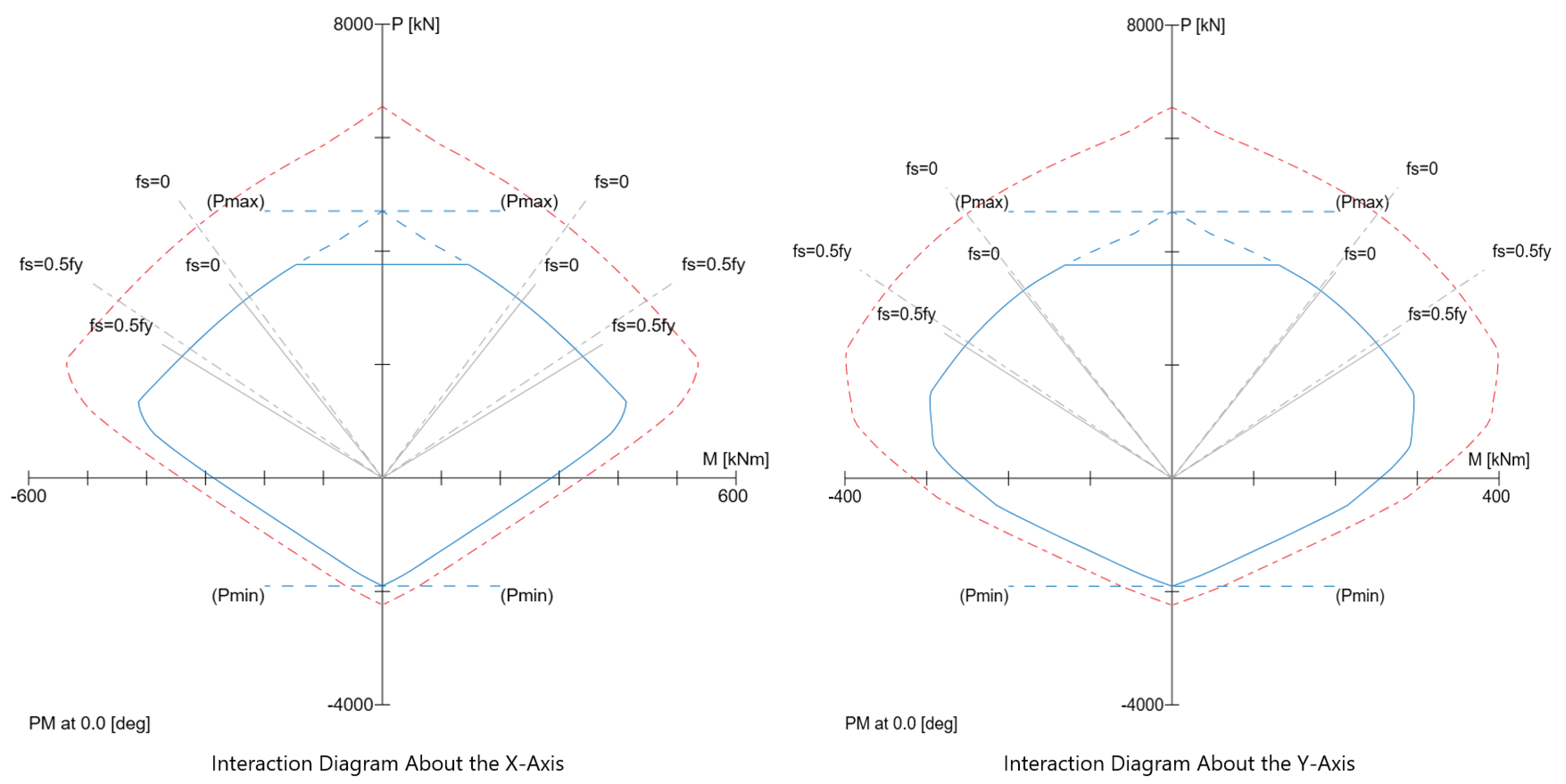
Figure 12 - Comparison of Column Interaction Diagrams about X-Axis and Y-Axis (spColumn)
In most building design calculations, such as the examples shown for flat plate or flat slab concrete floor systems, all building columns are subjected to Mx and My due to lateral forces and unbalanced moments from both directions of analysis. This requires an evaluation of the column P-M interaction diagram in two directions simultaneously (biaxial bending).
StructurePoint’s spColumn program can also evaluate column sections in biaxial mode to produce the results shown in the following Figure for the column section in this example.
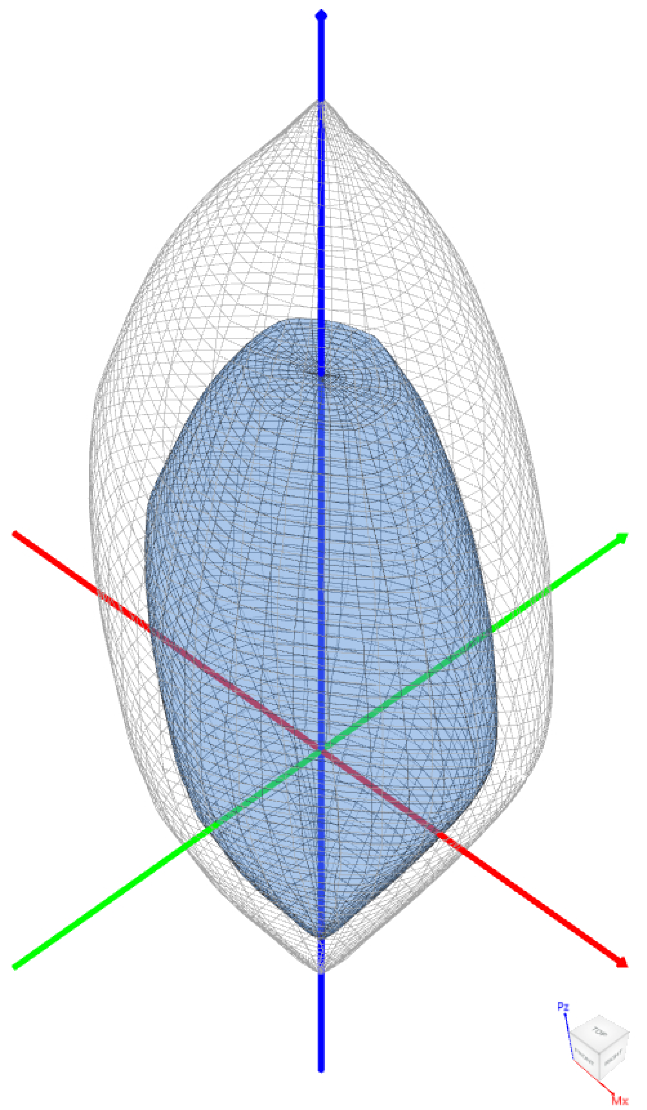
Figure 13 - Nominal & Design 3D Failure Surfaces (Biaxial) (spColumn)
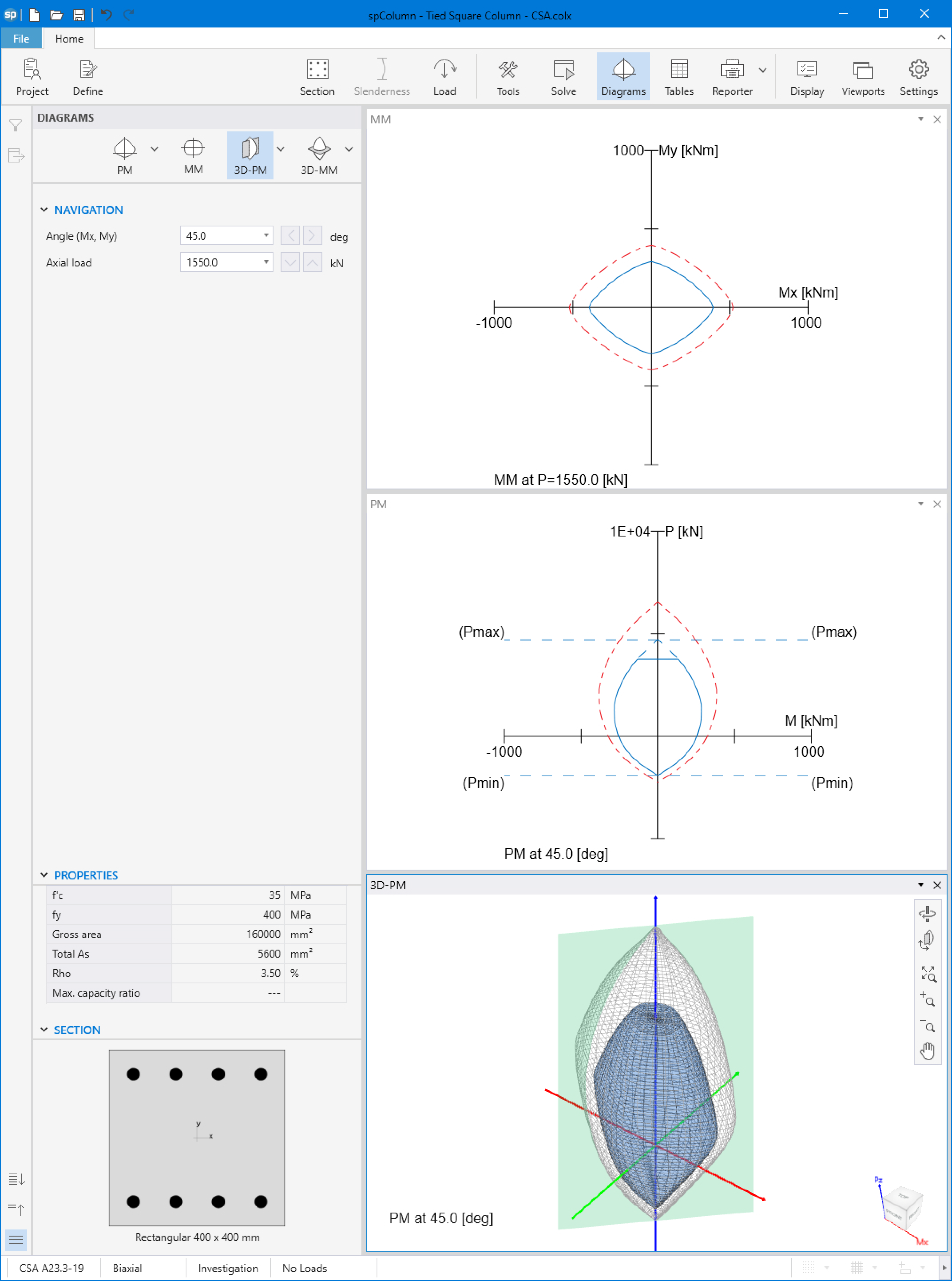
Figure 14 - Tied Column Interaction Diagram and 3D failure Surface Viewer (spColumn)
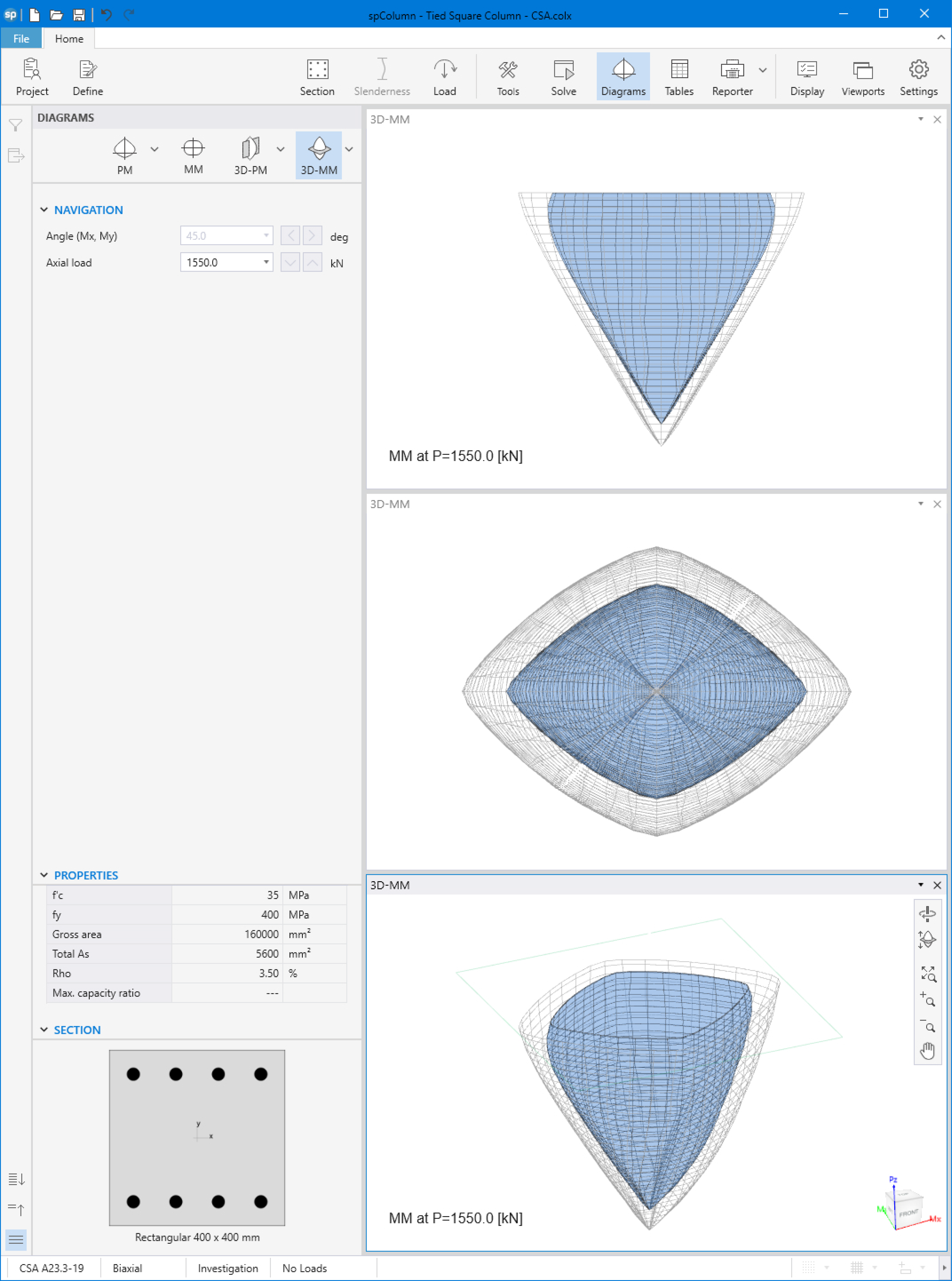
Figure 15 - Tied Column 3D Failure Surface with a Horizontal Plane Cut at P = 1,550.0 kN (spColumn)
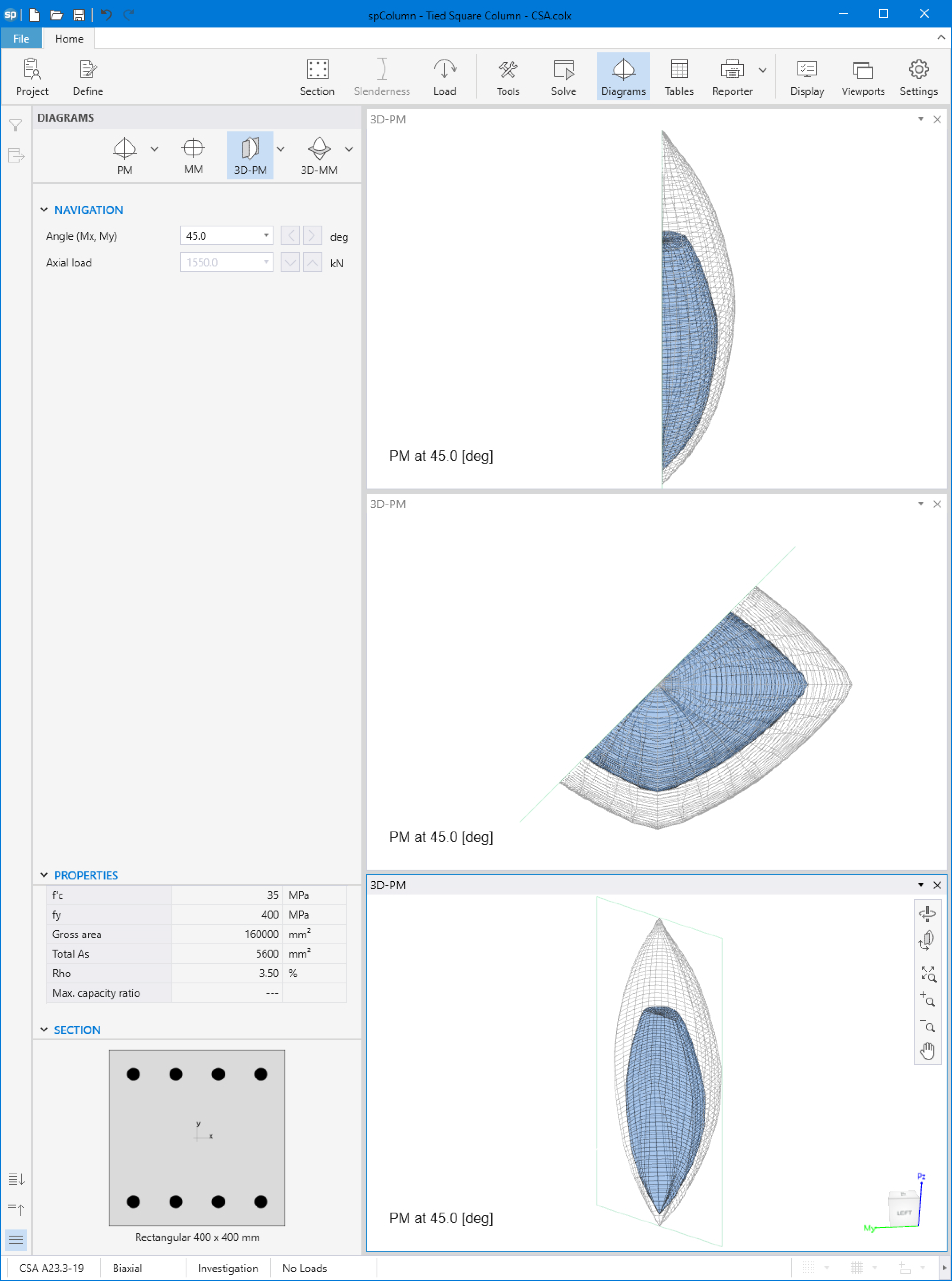
Figure 16 - Tied Column 3D Failure Surface with a Vertical Plane Cut at 45º (spColumn)