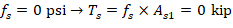
2. Bar Stress Near Tension Face Equal to Zero, (εs = fs = 0)
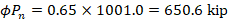
Figure 3 - Strains, Forces, and Moment Arms (εt = fs = 0)
Strain εs is zero in the extreme layer of tension steel. This case is considered when calculating an interaction diagram because it marks the change from compression lap splices being allowed on all longitudinal bars, to the more severe requirement of tensile lap splices. ACI 318-19 (10.7.5.2.1 and 2)
2.1. c, a, and strains in the reinforcement
Where c is the distance from the fiber of maximum compressive strain to the neutral axis. ACI 318-19 (22.2.2.4.2)
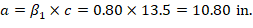
a = Depth of equivalent rectangular stress block


2.2. Forces in the concrete and steel


The area of the reinforcement in this layer has been included in the area (ab) used to compute Cc. As a result, it is necessary to subtract 0.85fc’ from fs’ before computing Cs: