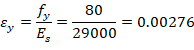
4. Bar Stress Near Tension Face Equal to fy, (fs = fy)
Figure 5 - Strains, Forces, and Moment Arms (fs = fy)
This strain distribution is called the balanced failure case and the compression-controlled strain limit. It marks the change from compression failures originating by crushing of the compression surface of the section, to tension failures initiated by yield of longitudinal reinforcement. It also marks the start of the transition zone for ϕ for columns in which ϕ increases from 0.65 (or 0.75 for spiral columns) up to 0.90.
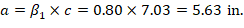
4.1. c, a, and strains in the reinforcement


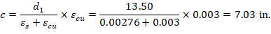
Where c is the distance from the fiber of maximum compressive strain to the neutral axis. ACI 318-19 (22.2.2.4.2)


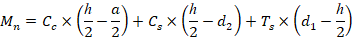
4.2. Forces in the concrete and steel

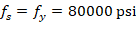


The area of the reinforcement in this layer has been included in the area (ab) used to compute Cc. As a result, it is necessary to subtract 0.85fc’ from fs’ before computing Cs: