2. Tilt-Up Wall Structural Analysis
2.1. Loads and Load Combinations
Roof dead load (PDLroof) | = 2.5 kip |
Roof live load (PLLroof) | = 2.0 kip |
Floor dead load (PDLfloor) | = 17.6 kip |
Floor live load (PLLfloor) | = 10.0 kip |
Wind load | = 27.2 psf (out-of-plane) |
= 0.00 psf (in-plane) |
The tributary width for loads can be taken as the width of the strip plus one-half the width of adjacent openings.
Joists loads at each floor level including the roof are divided between the individual strips assuming an equivalent simply supported beams with the supports at the centerline of each strip.
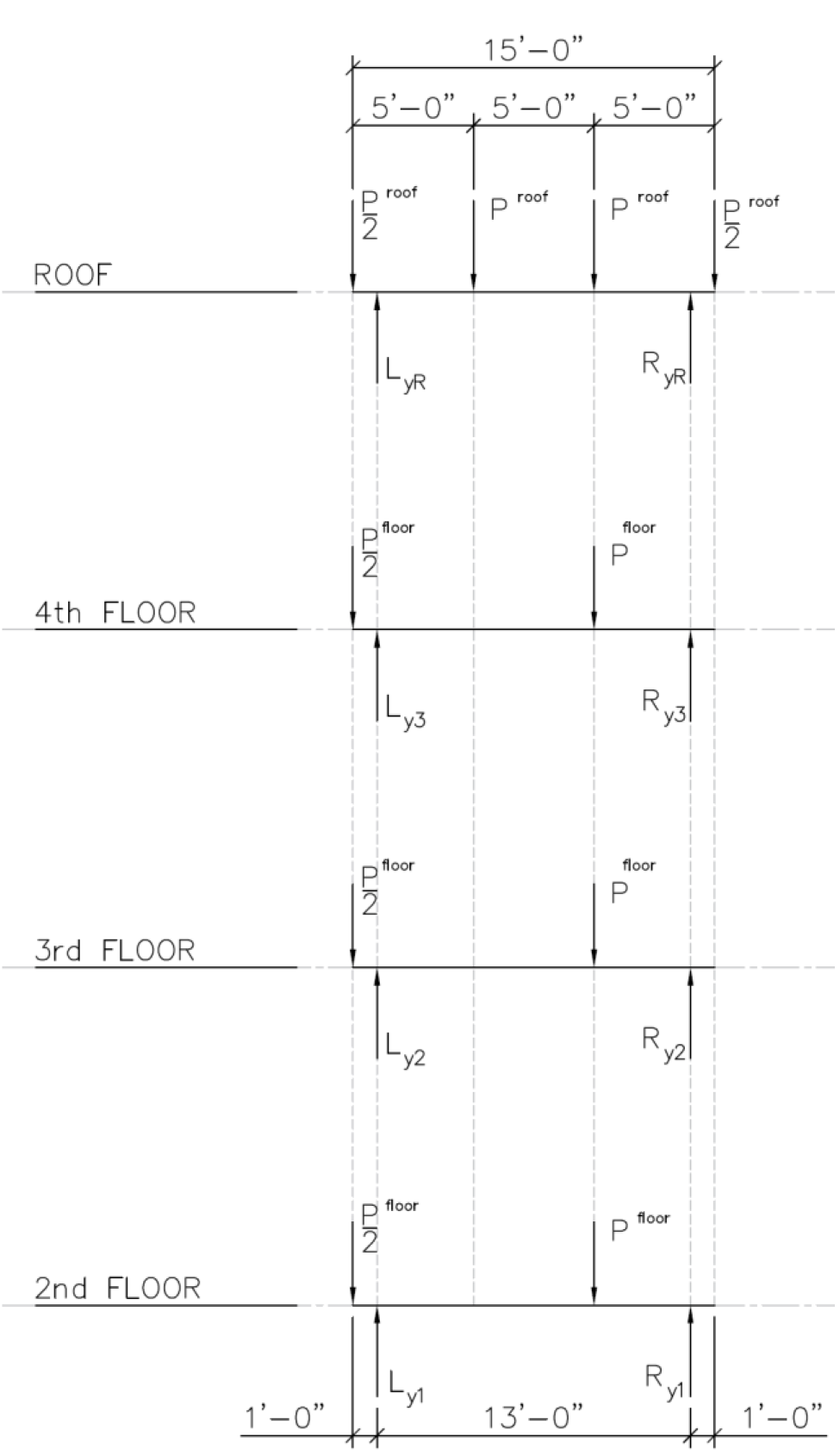
Figure 3 - Tilt-Up Design Strips Tributary Widths - Dead & Live Loads
Table 1 - Joists Loads at Each Floor Level | ||||
Floor Level | Left Strip (Ly) | Right Strip (Ry) | ||
PDL, kip | PLL, kip | PDL, kip | PLL, kip | |
First | 14.89 | 8.46 | 11.51 | 6.54 |
Second | 14.89 | 8.46 | 11.51 | 6.54 |
Third | 14.89 | 8.46 | 11.51 | 6.54 |
Roof | 3.75 | 3.00 | 3.75 | 3.00 |
For maximum positive 1st order moment section (43 ft):

For maximum negative 1st order moment section (17 ft):
Self-weight is calculated at the critical sections based on the 1st order moment diagram shown in the next section.
The load combination considered for structural analysis and design is 1.2D + 0.5Lr + 1.0L + 1.0W.
2.2. Wall First Order Structural Analysis
Using the loads and load combination calculated in the previous section, the moment diagram of 1st order moment can be obtained as shown in the following figure using the method illustrated later in this example.
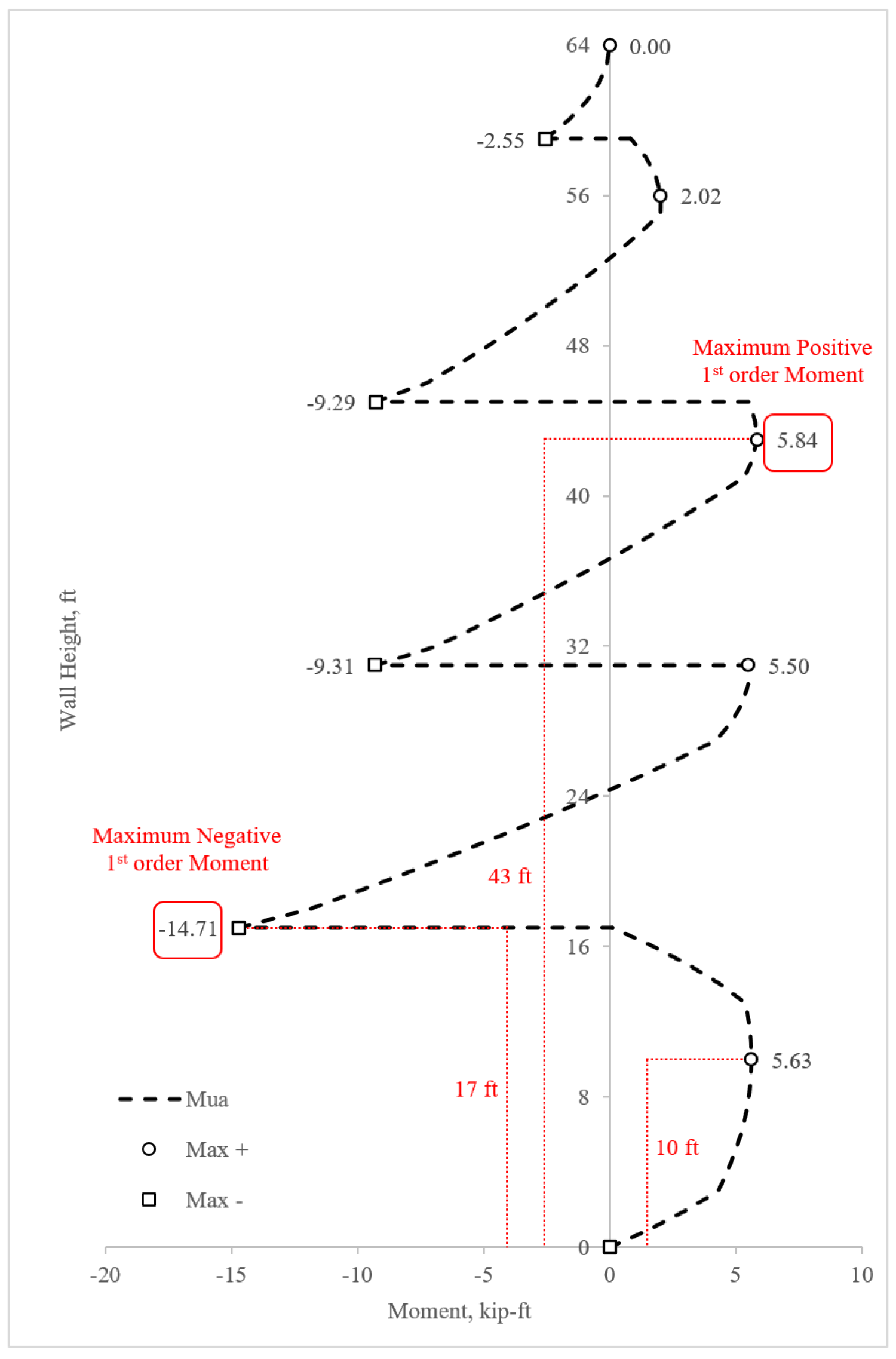
Figure 4 - 1st Order Moment Diagram for Left Strip
2.3. Wall Second Order Structural Analysis
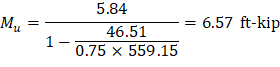
For maximum positive 1st order moment section (43 ft): The maximum factored wall forces including moment magnification due to second order (P-Δ) effects can be calculated as follows: Calculate the effective area of longitudinal reinforcement in a slender wall for obtaining an approximate cracked moment of inertia. ACI 318-14 (R11.8.3.1) The following calculation are performed with the effective area of steel in lieu of the actual area of steel. ACI 318-14 (R21.2.2) ACI 318-14 (Table 21.2.2) ACI 318-14 (11.8.3.1(c)) ACI 318-14 (19.2.2.1(b)) ACI 318-14 (11.8.3.1) ACI 318-14 (11.8.3.1(c)) ACI 318-14 (Eq. 11.8.3.1(d)) Where Mua is the maximum factored moment along the wall due to lateral and eccentric vertical loads, not including PΔ (second order) effects. This value can be seen in the previous figure. ACI 318-14 (11.8.3.1)
2.4. Tension-controlled verification
ACI 318-14 (11.8.1.1(b)) Therefore, section is tension controlled ACI 318-14 (Table 21.2.2)