4.1. Required and Provided Reinforcement
For this beam, the moment at the fixed end governs the design as shown in the previous Figure.
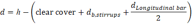
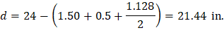
Use #9 bars with 1.5 in. concrete clear cover per ACI 318-14 (Table 20.6.1.3.1). The distance from extreme compression fiber to the centroid of longitudinal tension reinforcement, d, is calculated below:
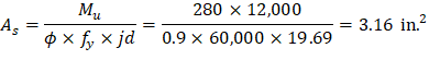
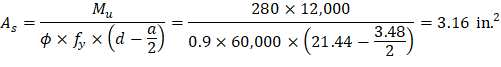
To determine the area of steel, assumptions have to be made whether the section is tension or compression controlled, and regarding the distance between the resultant compression and tension forces along the beam section (jd). In this example, tension-controlled section will be assumed so the reduction factor ϕ is equal to 0.9, and jd will be taken equal to 0.919d. The assumptions will be verified once the area of steel is finalized.


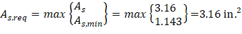
The required reinforcement at initial trial is calculated as follows:
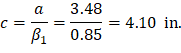
Recalculate ‘a’ for the actual As = 3.16 in.2:
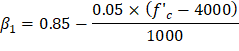
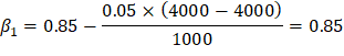
Where:
| ACI 318-14 (Table 22.2.2.4.3) |
| |
|

Therefore, the assumption that section is tension-controlled is valid.
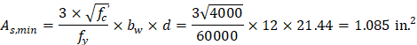
The minimum reinforcement shall not be less than
| ACI 318-14 (9.6.1.2(a)) |
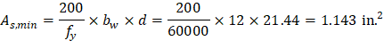
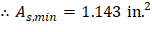
And not less than
| ACI 318-14 (9.6.1.2(b)) |
 3
3
Provide 4 – #9 bars:

4.2. Spacing of Longitudinal Reinforcement
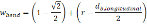
| spBeam Manual (Eq. 2-96) |
Where r is the inside radius of bend for stirrup = 4 × stirrup radius = 4 × 0.50/2 = 1 in. | |
| spBeam Manual (Figure 2.21) |
| |
|
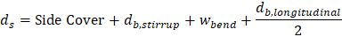
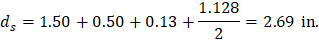
Where:
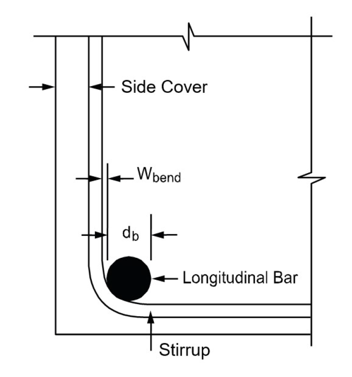
Figure 4 – Width Due to Stirrup Bend (spBeam Manual – Figure 2.21)
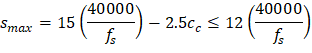
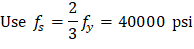
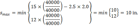
The maximum allowed spacing (smax):
| ACI 318-14 (Table 24.3.2) |
cc = the least distance from surface of reinforcement to the tension face = 2.0 in. | |
| ACI 318-14 (24.3.2.1) |
|
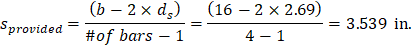
The minimum allowed spacing (smin):
| CRSI 2002 (Figure 12-9) |
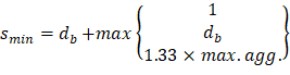
Where the maximum aggregate size is ¾”
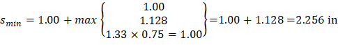
smin = 2.256 in. < sprovided = 3.539 in. < smax = 10.000 in.
Therefore, 4 - #9 bars are o.k.