4. Cantilever Retaining Wall Analysis and Design - spWall Software
spWall is a program for the analysis and design of reinforced concrete shear walls, tilt-up walls, precast walls, retaining walls, tank walls and Insulate Concrete Form (ICF) walls. It uses a graphical interface that enables the user to easily generate complex wall models. Graphical user interface is provided for:
• Wall geometry (including any number of openings and stiffeners)
• Material properties including cracking coefficients
• Wall loads (point, line, and area),
• Support conditions (including translational and rotational spring supports)
spWall uses the Finite Element Method for the structural modeling, analysis, and design of slender and non-slender reinforced concrete walls subject to static loading conditions. The wall is idealized as a mesh of rectangular plate elements and straight line stiffener elements. Walls of irregular geometry are idealized to conform to geometry with rectangular boundaries. Plate and stiffener properties can vary from one element to another but are assumed by the program to be uniform within each element.
Six degrees of freedom exist at each node: three translations and three rotations relating to the three Cartesian axes. An external load can exist in the direction of each of the degrees of freedom. Sufficient number of nodal degrees of freedom should be restrained in order to achieve stability of the model. The program assembles the global stiffness matrix and load vectors for the finite element model. Then, it solves the equilibrium equations to obtain deflections and rotations at each node. Finally, the program calculates the internal forces and internal moments in each element. At the user’s option, the program can perform second order analysis. In this case, the program takes into account the effect of in-plane forces on the out-of-plane deflection with any number of openings and stiffeners.
In spWall, the required flexural reinforcement is computed based on the selected design standard (ACI 318-14 is used in this case study), and the user can specify one or two layers of wall reinforcement. In stiffeners and boundary elements, spWall calculates the required shear and torsion steel reinforcement. Wall concrete strength (in-plane and out-of-plane) is calculated for the applied loads and compared with the code permissible shear capacity.
For illustration purposes, the following figures provide a sample of the input modules and results obtained from an spWall model created for the cantilever retaining wall in this design example.
4.1. Cantilever Retaining Wall Model Input

Figure 4 - spWall Interface

Figure 5 - Assigning Soil Loads for Cantilever Retaining Wall (spWall)

Figure 6 - Solve and Mesh Options (spWall)
4.2. Cantilever Retaining Wall Results Contours

Figure 7 - Factored Axial Force Contour (spWall)
_v2.svg)
Figure 8 - Lateral Displacement Contour (Out-of-Plane) (spWall)
4.3. Cantilever Retaining Wall Cross-Sectional Forces

Figure 9 - Axial Load Diagram (spWall)

Figure 10 - Out-of-Plane Shear Diagram (spWall)

Figure 11 - Bending Moment Diagram (spWall)

Figure 12 - Required Vertical Reinforcement (spWall)
(Note: Minimum reinforcement value shown is based on the top wall stem thickness of 8” while the hand calculations show the minimum required at the wall stem base with 16” thickness)
4.4. Cantilever Retaining Wall Maximum Displacement
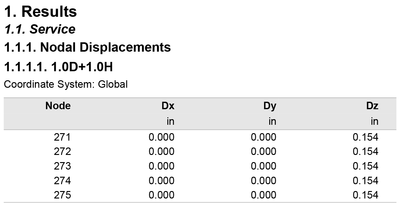
Figure 13 - Displacement at Critical Sections (Service Combinations) (spWall)
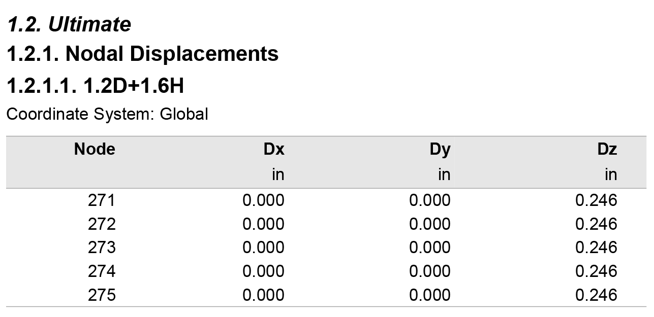
Figure 14 - Displacement at Critical Sections (Ultimate Combinations) (spWall)
4.5. Cantilever Retaining Wall Cross-Sectional Forces at Stem Base

Figure 15 - Wall Cross-Sectional Forces (spWall)
4.6. Cantilever Retaining Wall Reinforcement
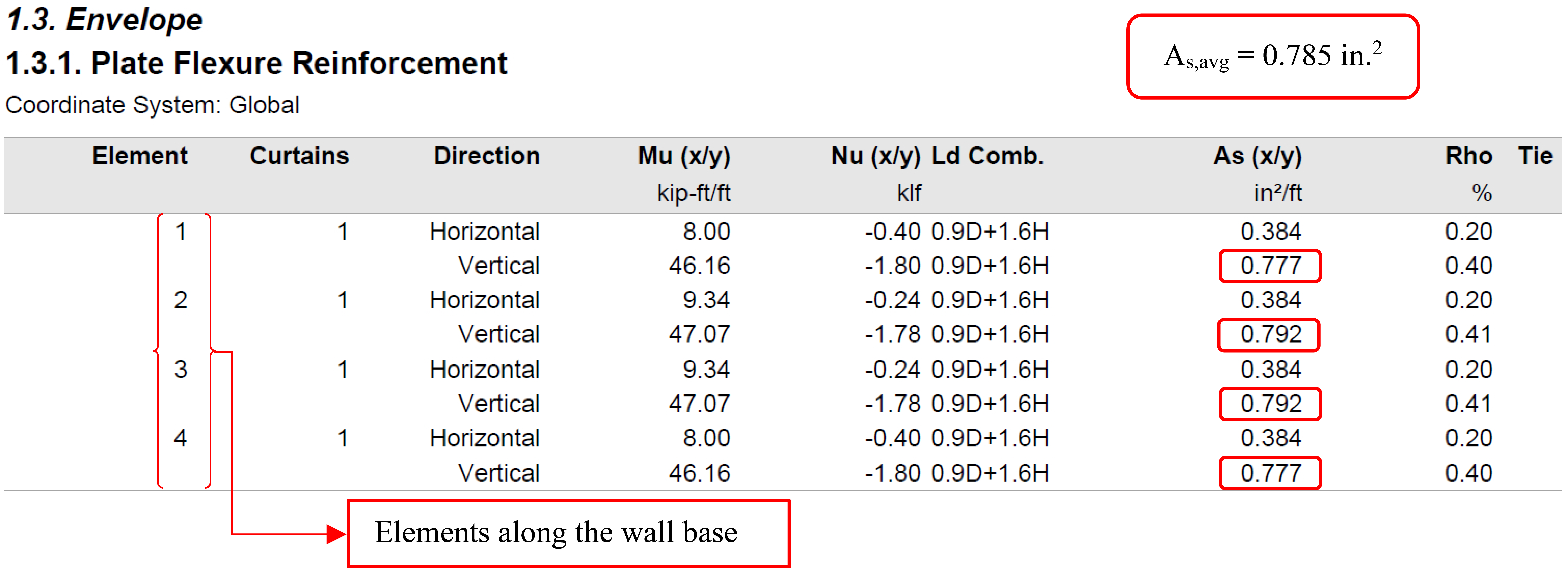
Figure 16 - Required Vertical Reinforcement (spWall)