5. Moment Magnification along Length of Compression Member
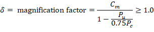
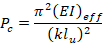
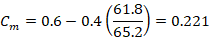
In sway frames, second-order effects shall be considered along the length of columns. It shall be permitted to account for these effects using ACI 318-19 (6.6.4.5) (Nonsway frame procedure), where Cm is calculated using M1 and M2 from ACI 318-19 (6.6.4.6.1) as follows: ACI 318-19 (6.6.4.6.4)

M2 = the second-order factored moment.
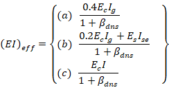
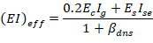
There are three options for calculating the effective flexural stiffness of slender concrete columns (EI)eff. The second equation provides accurate representation of the reinforcement in the section and will be used in this example and is also used by the solver in spColumn.
Further comparison of the available options is provided in “Effective Flexural Stiffness for Critical Buckling Load of Concrete Columns” technical note.
5.1. Gravity Load Combination #2 (Gravity Loads Only)
 ACI 318-19 (Table 6.6.3.1.1(a))

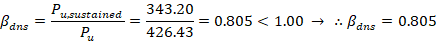
βdns is the ratio of maximum factored sustained axial load to maximum factored axial load associated with the same load combination. ACI 318-19 (6.6.4.4.4)


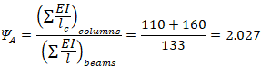
 (Calculated previously) ACI 318-19 (Figure R6.2.5.1)
 (Column essentially fixed at base) ACI 318-19 (Figure R6.2.5.1)
Using Figure R6.2.5.1(a) from ACI 318-19 à k = 0.656 as shown in the figure below for the exterior column.
Figure 5 - Effective Length Factor (k) Calculations for Exterior Columns (Nonsway)
With 8-#6 reinforcement equally distributed on all sides Ise = 111.5 in.4 (Ref. uses approximate value of 150 in.4 in lieu of exact value calculated by spColumn).


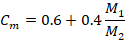


Since the column is bent in double curvature, M1/M2 is positive. ACI 318-19 (6.6.4.5.3)
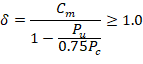
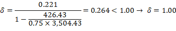

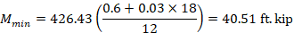
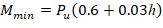
Where Pu = 426.4 kip, and h = the section dimension in the direction being considered = 18 in.


Mc1 and Mc2 will be considered separately to ensure proper comparison of resulting magnified moments against negative and positive moment capacities of unsymmetrical sections as can be seen in the following figure.
Figure 6 - Column Interaction Diagram for Unsymmetrical Section
5.2. Lateral Load Combination #6 (Gravity Plus Wind Loads)
 ACI 318-19 (Table 6.6.3.1.1(a))

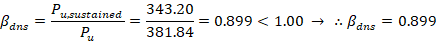
βdns is the ratio of maximum factored sustained axial load to maximum factored axial load associated with the same load combination. ACI 318-19 (6.6.4.4.4)

 (Calculated previously) ACI 318-19 (Figure R6.2.5.1)
 (Column essentially fixed at base) ACI 318-19 (Figure R6.2.5.1)
Using Figure R6.2.5.1(a) from ACI 318-19 à k = 0.656
With 8-#6 reinforcement equally distributed on all sides Ise = 111.5 in.4 (Ref. uses approximate value of 150 in.4 in lieu of exact value calculated by spColumn).


Since the column is bent in double curvature, M1/M2 is positive. ACI 318-19 (6.6.4.5.3)


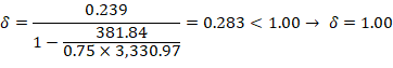
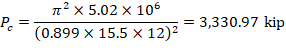
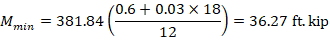
Where Pu = 381.8 kip, and h = the section dimension in the direction being considered = 18 in.


Mc1 and Mc2 are considered separately to ensure proper comparison of resulting magnified moments against negative and positive moment capacities of unsymmetrical sections.
A summary of the moment magnification factors and magnified moments for the exterior column for all load combinations using both equation options ACI 318-19 (6.6.4.6.2(a)) and (6.6.4.6.2(b)) to calculate δs is provided in the table below for illustration and comparison purposes.
For column design ACI 318 requires the second-order moment to first-order moment ratios should not exceed 1.40. If this value is exceeded, the column design needs to be revised. ACI 318-19 (6.2.5.3)
* Cutoff value of Mmin is applied to M1(1st) and M2(1st) in order to avoid unduly large ratios in cases where M1(1st) and M2(1st) moments are smaller than Mmin.