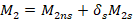
4. Moment Magnification at Ends of Compression Member
A detailed calculation for load combination 4 (gravity plus wind) is shown below to illustrate the procedure. Table 3 summarizes the magnified moment computations for the exterior columns.
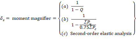
ACI 318-19 (6.6.4.6.2(b)) will be used for comparison purposes with results obtained from spColumn model. However, (a) and (c) can also be used to calculate the moment magnifier.
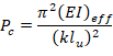
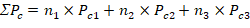
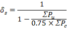
∑Pu is the summation of all the factored vertical loads in the first story, and ∑Pc is the summation of the critical buckling load for all sway-resisting columns in the first story.
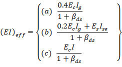
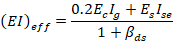
There are three options for calculating the effective flexural stiffness of slender concrete columns (EI)eff. The second equation provides accurate representation of the reinforcement in the section and will be used in this example and is also used by the solver in spColumn.
Further comparison of the available options is provided in “Effective Flexural Stiffness for Critical Buckling Load of Concrete Columns” technical note.
 ACI 318-19 (Table 6.6.3.1.1(a))

βds is the ratio of maximum factored sustained shear within a story to the maximum factored shear in that story associated with the same load combination. The maximum factored sustained shear in this example is equal to zero leading to βds = 0. ACI 318-19 (6.6.3.1.1)
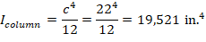
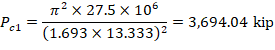
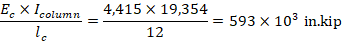
For exterior columns with one beam framing into them in the direction of analysis (12 columns):
With 8-#8 reinforcement equally distributed on all sides and 22 in. x 22 in. column section à Ise = 352.6 in.4.

k = 1.693 (calculated previously).
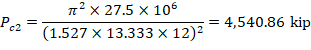
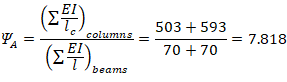
For exterior columns with two beams framing into them in the direction of analysis (4 columns):
 (Column essentially fixed at base) ACI 318-19 (Figure R6.2.5.1)
Using Figure R6.2.5.1 from ACI 318-19 à k = 1.527 as shown in the figure below for the exterior columns with two beams framing into them in the directions of analysis.
Figure 3 - Effective Length Factor (k) Calculations for Exterior Columns with Two Beams Framing into them in the Direction of Analysis
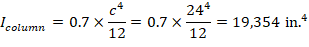
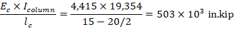
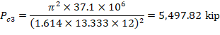
For interior columns (8 columns):
 ACI 318-19 (Table 6.6.3.1.1(a))

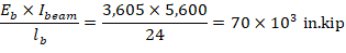
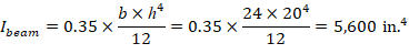
For beams framing into the columns:

 ACI 318-19 (Table 6.6.3.1.1(a))
 (Column essentially fixed at base) ACI 318-19 (Figure R6.2.5.1)
Using Figure R6.2.5.1 from ACI 318-19 à k = 1.614 as shown in the figure below for the interior columns.
Figure 4 - Effective Length Factor (k) Calculations for Interior Columns
With 8-#8 reinforcement equally distributed on all sides and 24 in. x 24 in. column section à Ise = 439.1 in.4.


A summary of the moment magnification factors and magnified moments for the exterior column for all load combinations using both equation options ACI 318-19 (6.6.4.4.4(a)) and (6.6.4.4.4(b)) to calculate (EI)eff is provided in the table below for illustration and comparison purposes. Note: The designation of M1 and M2 is made based on the second-order (magnified) moments and not based on the first-order (unmagnified) moments.