To model a single layer of reinforcing, cover distance for top and bottom reinforcement should be input such that they are at the same plane per each of the x and y directions. The reinforcement location is measured to the centerline of reinforcement. For a 6 in. thick slab on grade and assuming No. 4 bars with 2 in. clear cover at the top, the reinforcement location for single layer reinforcement is entered for top layer and bottom layer such that both are at the same horizontal plane. (i.e. 2.25 in. from top of the slab and 3.75 in. from bottom of the slab for a 6 in. thick slab).
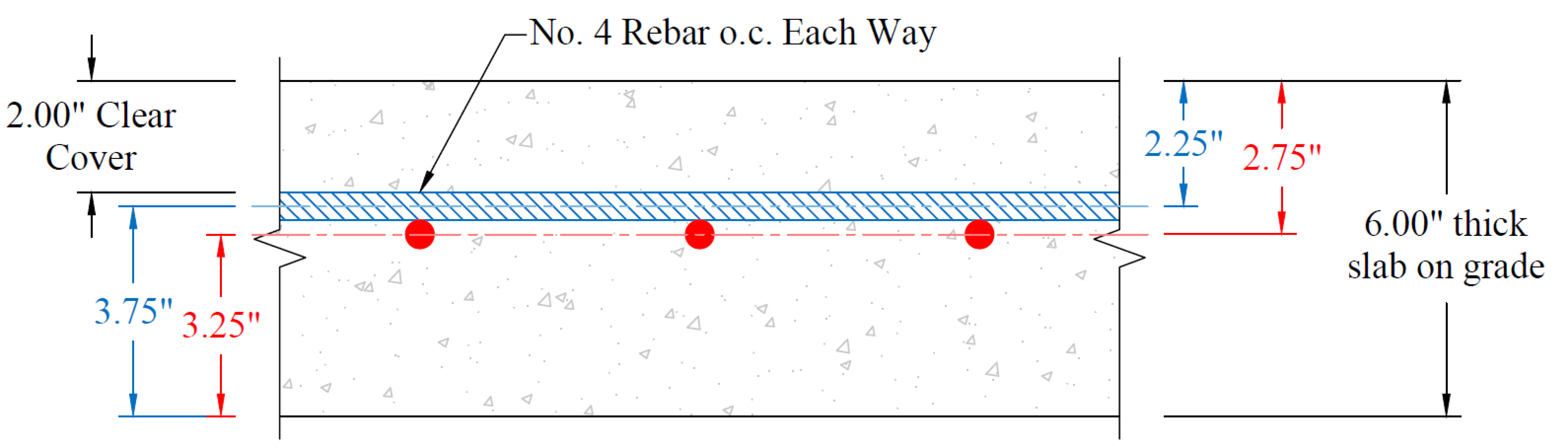
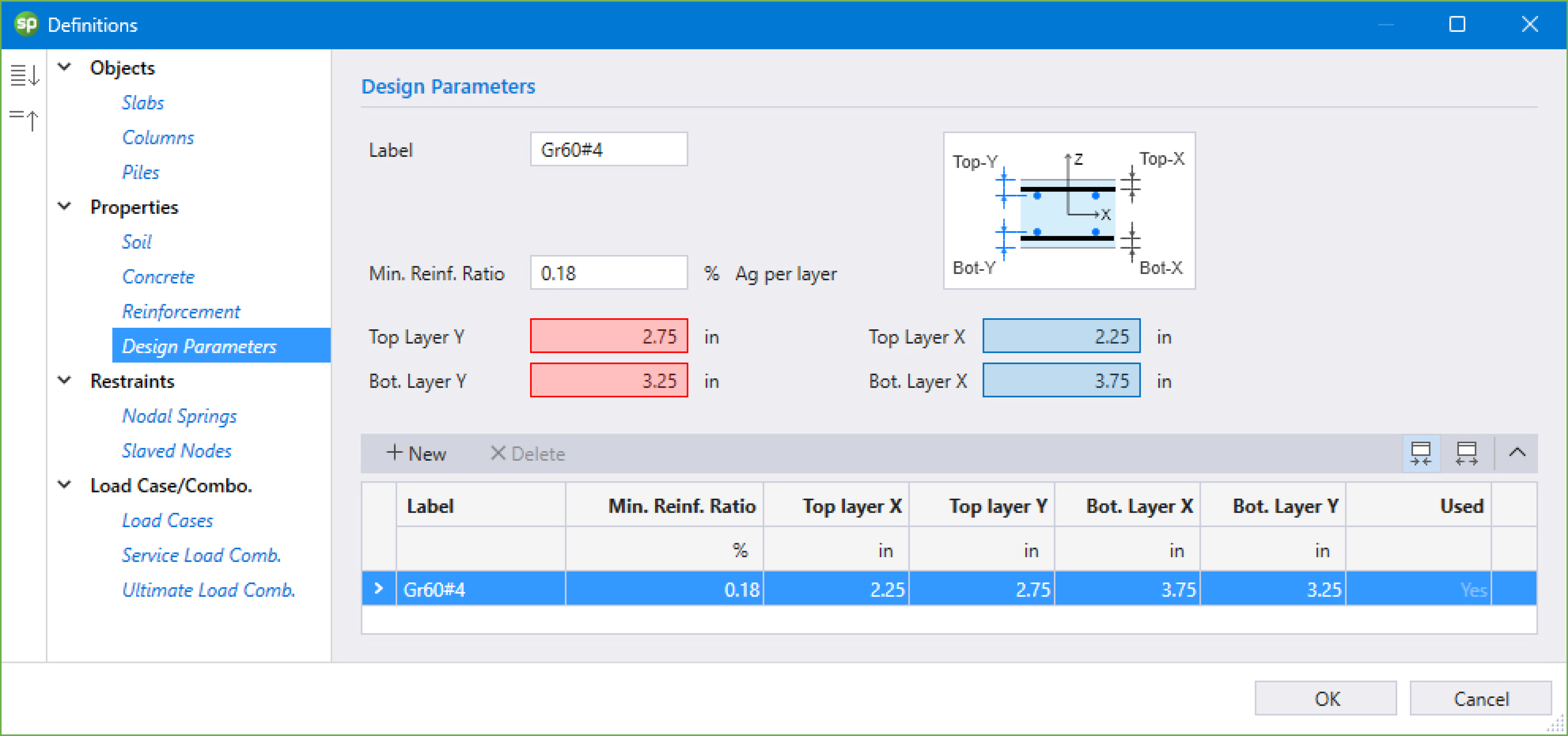
Figure 2 - Design Parameters Input
The reinforcement location input should be adjusted depending on bar sizes. For example, if No. 6 bars are to be utilized, reinforcement locations will be as follows:
Top Layer – X-Dir. = 2.00 + 0.75/2 = 2.375 in. | Top Layer – Y-Dir. = 2.375 + 0.75 = 3.125 in |
Bottom Layer – X-Dir. = 6.00 + 2.375 = 3.625 in. | Bottom Layer – X-Dir. = 6.00 + 3.125 = 2.875 in. |
The top reinforcement layer input is used by the Program to calculate the reinforcement area required per unit length to resist tension at the top of the slab. Similarly, the bottom reinforcement layer input is used by the Program to calculate the reinforcement area required per unit length to resist tension at the bottom of the slab. Since both of these layers are in the same horizontal plane, the envelope value of the top and bottom reinforcement is to be selected as governing reinforcement in each direction. To meet code minimum reinforcement ratio (% of Ag per layer) input is entered as 0.18% of gross concrete area as opposed to 0.09% for models with two layers of reinforcement.
When Welded-Wire-Fabric (WWF) reinforcement is used, the Design Parameter Input for W9.5 wire is shown below as an example:
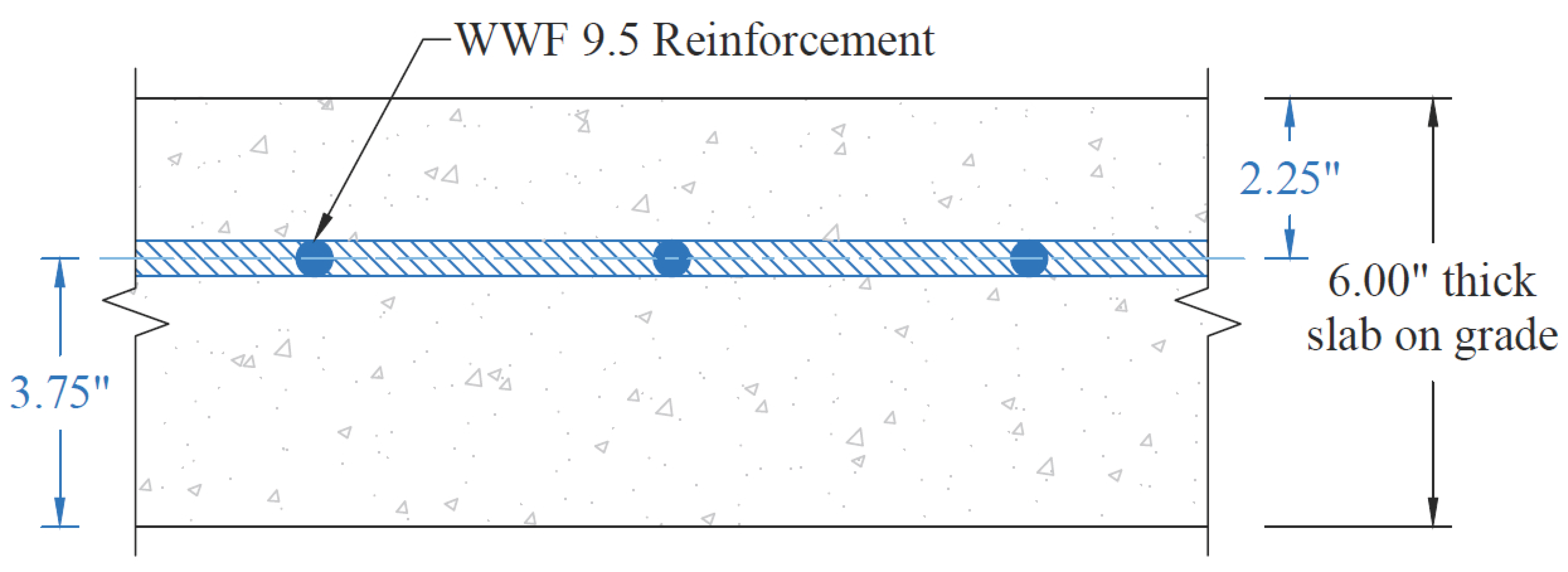
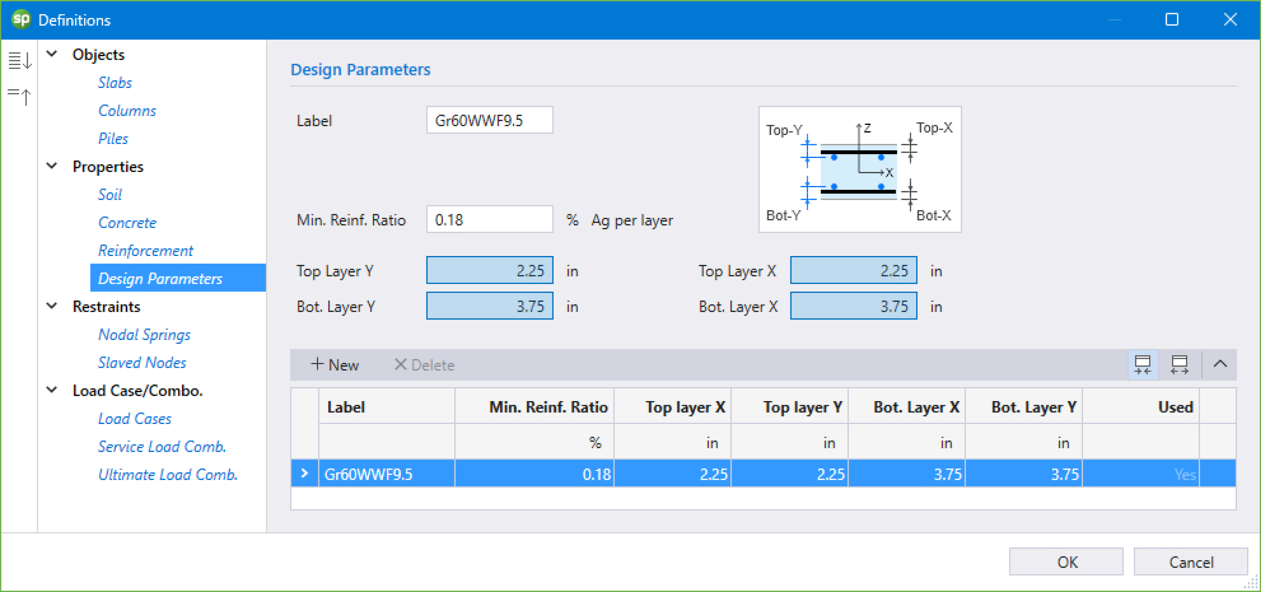
Figure 3 - Design Parameters Input - Welded-Wire Fabric (WWF)