3. Design of Interior, Edge, and Corner Columns
This section includes the design of interior, edge, and corner columns using spColumn software. The preliminary dimensions for these columns were calculated previously in section one. The reduction of live load per ASCE 7-10 will be ignored in this example. However, the detailed procedure to calculate the reduced live loads is explained in the “One-Way Wide Module Joist Concrete Floor Design” Design Example.
3.1. Determination of Factored Loads
Assume 4 story building
Interior Column (Column #1):
Tributary area for interior column is ATributary = (18 × 14) = 252 ft2
• Pu | = | 4 × qu × ATributary = 4 × 0.193 × 252 = 194.54 kips |
• Mu,x | = | 3.66 ft-kips (see the previous Table) |
• Mu,y | = | 2.27 ft-kips (see the previous Table) |
Edge (Exterior) Column (Column #2):
Tributary area for interior column is
• Pu | = | 4 × qu × ATributary = 4 × 0.193 × 126 = 97.27 kips |
• Mu,x | = | 22.15 ft-kips (see the previous Table) |
• Mu,y | = | 1.23 ft-kips (see the previous Table) |
Edge (Exterior) Column (Column #3):
Tributary area for interior column is
• Pu | = | 4 × qu × ATributary = 4 × 0.193 × 126 = 97.27 kips |
• Mu,x | = | 2.05 ft-kips (see the previous Table) |
• Mu,y | = | 12.26 ft-kips (see the previous Table) |
Corner Column (Column #4):
Tributary area for interior column is 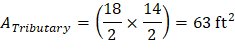
• Pu | = | 4 × qu × ATributary = 4 × 0.193 × 63 = 48.64 kips |
• Mu,x | = | 12.47 ft-kips (see the previous Table) |
• Mu,y | = | 6.78 ft-kips (see the previous Table) |
3.2. Column Capacity Diagram (Axial-Moment Interaction Diagram)


