Shear strength of the slab in the vicinity of columns/supports includes an evaluation of one-way shear (beam action) and two-way shear (punching) in accordance with ACI 318 Chapter 22.
4.1. One-Way (Beam Action) Shear Strength
| ACI 318-14 (22.5) |
One-way shear is critical at a distance d from the face of the column as shown in Figure 3. Figures 21 and Figure 22 show the factored shear forces (Vu) at the critical sections around each column and each drop panel, respectively. In members without shear reinforcement, the design shear capacity of the section equals to the design shear capacity of the concrete:
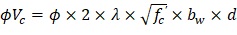
| ACI 318-14 (Eq. 22.5.1.1) |
Where: | |
| ACI 318-14 (Eq. 22.5.5.1) |
Note: The calculations below follow one of two possible approaches for checking one-way shear. Refer to the conclusions section for a comparison with the other approach.
4.1.1. At Distance d from the Supporting Column
Where λ = 1 for normal weight concrete Because ϕVc ≥ Vu at all the critical sections, the slab has adequate one-way shear strength.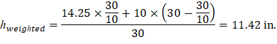
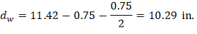
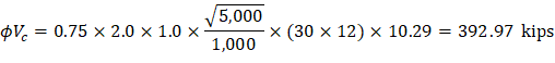
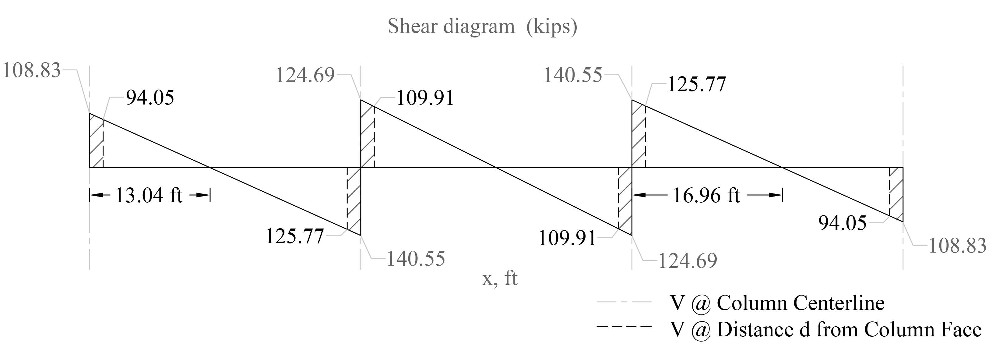
Figure 21 - One-way Shear at Critical Sections (at Distance d from the Face of the Supporting Column)
4.1.2. At the Face of the Drop Panel
h = 10 in. | |
| |
Where λ = 1 for normal weight concrete | |
| |
Because ϕVc ≥ Vu at all the critical sections, the slab has adequate one-way shear strength. |
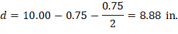
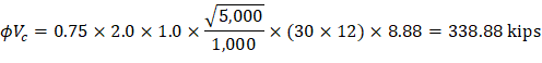
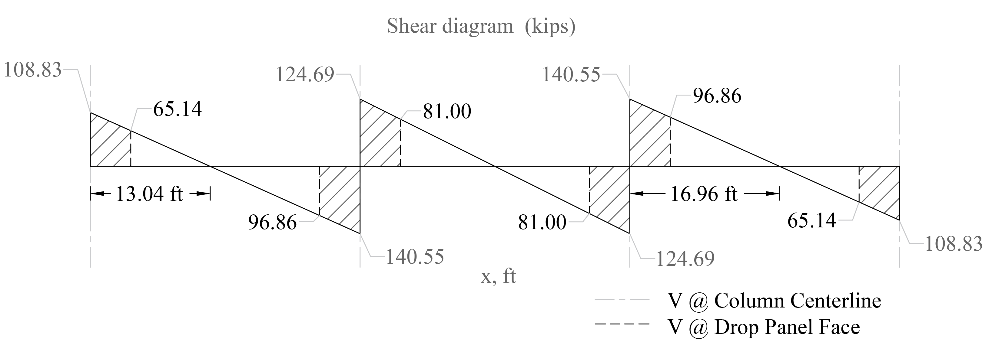
Figure 22 - One-Way Shear at Critical Sections (at the Face of the Drop Panel)
4.2. Two-Way (Punching) Shear Strength
ACI 318-14 (22.6)
4.2.1. Around the Columns Faces
Two-way shear is critical on a rectangular section located at d/2 away from the face of the column as shown in Figure 18.
a) Exterior column:
The factored shear force (Vu) in the critical section is computed as the reaction at the centroid of the critical section minus the self-weight and any superimposed surface dead and live load acting within the critical section (d/2 away from column face).

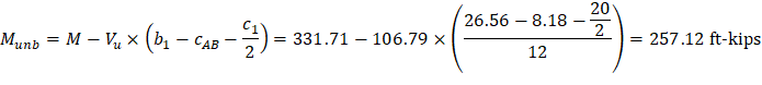
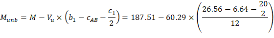
The factored unbalanced moment used for shear transfer, Munb, is computed as the sum of the joint moments to the left and right. Moment of the vertical reaction with respect to the centroid of the critical section is also taken into account.
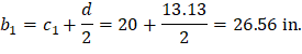
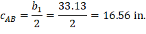
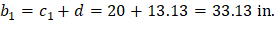
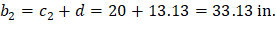
For the exterior column in Figure 18 the location of the centroidal axis z-z is:

Where:
|
| |
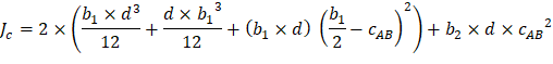
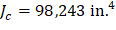
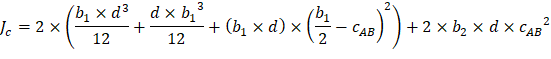
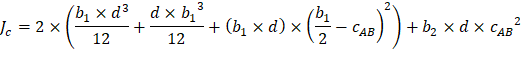
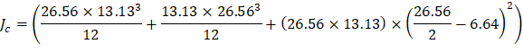
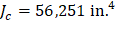
The polar moment Jc of the shear perimeter is: | ||
| ||
| ||
| ||
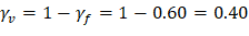
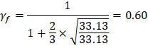
| ACI 318-14 (Eq. 8.4.4.2.2) | |
Where: | ||
| ACI 318-14 (8.4.2.3.2) | |
| ||
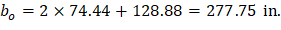
The length of the critical perimeter for the exterior column: | ||
| ||
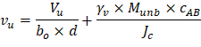
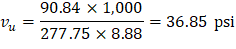
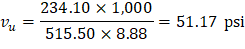
The two-way shear stress (vu) can then be calculated as: | ||
| ACI 318-14 (R.8.4.4.2.3) | |
| ||
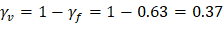
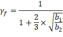
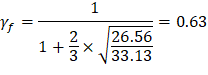
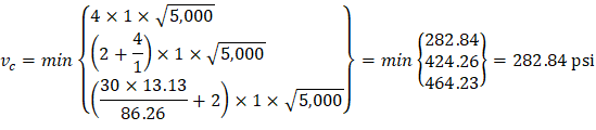
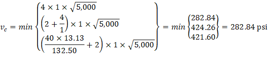
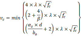
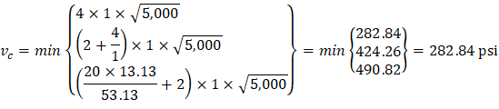
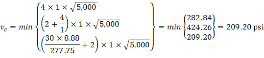
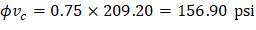
| ACI 318-14 (Table 22.6.5.2) | |
| ||
| ||
Because ϕvc ≥ vu at the critical section, the slab has adequate two-way shear strength at this joint. | ||


b) Interior column:


For the interior column in Figure 18, the location of the centroidal axis z-z is:
Where:
|
| |
The polar moment Jc of the shear perimeter is: | ||
| ||
| ||
| ||
| ACI 318-14 (Eq. 8.4.4.2.2) | |
Where: | ||
| ACI 318-14 (8.4.2.3.2) | |
| ||
The length of the critical perimeter for the interior column: | ||
| ||
The two-way shear stress (vu) can then be calculated as: | ||
| ACI 318-14 (R.8.4.4.2.3) | |
| ||
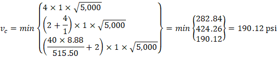
| ACI 318-14 (Table 22.6.5.2) | |
| ||
| ||
Because ϕvc ≥ vu at the critical section, the slab has adequate two-way shear strength at this joint. | ||


c) Corner column:
In this example, interior equivalent frame strip was selected where it only have exterior and interior supports (no corner supports are included in this strip). However, the two-way shear strength of corner supports usually governs. Thus, the two-way shear strength for the corner column in this example will be checked for educational purposes. Same procedure is used to find the reaction and factored unbalanced moment used for shear transfer at the centroid of the critical section for the corner support for the exterior equivalent frame strip.

For the corner column in Figure 18, the location of the centroidal axis z-z is:

Where:
|
| |
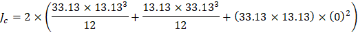
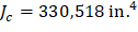
The polar moment Jc of the shear perimeter is: | ||
| ||
| ||
| ||
| ACI 318-14 (Eq. 8.4.4.2.2) | |
Where: | ||
| ACI 318-14 (8.4.2.3.2) | |
| ||
The length of the critical perimeter for the exterior column: | ||
| ||
The two-way shear stress (vu) can then be calculated as: | ||
| ACI 318-14 (R.8.4.4.2.3) | |
| ||
| ACI 318-14 (Table 22.6.5.2) | |
| ||
| ||
Because ϕvc ≥ vu at the critical section, the slab has adequate two-way shear strength at this joint. | ||


Two-way shear is critical on a rectangular section located at d/2 away from the face of the drop panel.
Note: The two-way shear stress calculations around drop panels do not have the term for unbalanced moment since drop panels are a thickened portion of the slab and are not considered as a support.
a) Exterior drop panel:
| ||
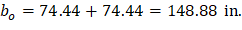
The length of the critical perimeter for the exterior drop panel: | ||
| ||
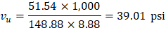
The two-way shear stress (vu) can then be calculated as: | ||
| ACI 318-14 (R.8.4.4.2.3) | |
| ||
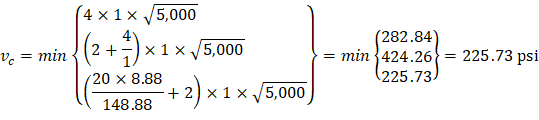
| ACI 318-14 (Table 22.6.5.2) | |
| ||
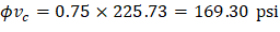
| ||
Because ϕvc ≥ vu at the critical section, the slab has adequate two-way shear strength around this drop panel. | ||


b) Interior drop panel:
| ||
The length of the critical perimeter for the interior drop panel: | ||
| ||
The two-way shear stress (vu) can then be calculated as: | ||
| ACI 318-14 (R.8.4.4.2.3) | |
| ||
| ACI 318-14 (Table 22.6.5.2) | |
| ||
| ||
Because ϕvc ≥ vu at the critical section, the slab has adequate two-way shear strength around this drop panel. | ||


c) Corner drop panel:
| ||
The length of the critical perimeter for the corner drop panel: | ||
| ||
The two-way shear stress (vu) can then be calculated as: | ||
| ACI 318-14 (R.8.4.4.2.3) | |
| ||
| ACI 318-14 (Table 22.6.5.2) | |
| ||
| ||
Because ϕvc ≥ vu at the critical section, the slab has adequate two-way shear strength around this drop panel. | ||