2.1. Introduction
spSlab and spBeam are advanced software tools used worldwide for the modeling, analysis, and design of reinforced concrete floor slab and beam systems. They are designed to handle two-way and one-way slab systems, including flat plates, flat slabs, slabs on beams, slab bands, two-way waffle slabs, one-way solid slabs, one-way ribbed slabs, rectangular beams, and flanged beams. Equipped with the American (ACI 318) and Canadian (CSA A23.3) concrete codes, spSlab and spBeam provide robust solutions for analyzing and designing conventional concrete floor systems under various loading conditions. The programs leverage sophisticated methods, such as the Equivalent Frame Method and the Matrix Stiffness Method, to perform analyses that comply with code provisions while offering flexibility in modeling and adaptability to diverse design and investigation scenarios. Their comprehensive approach includes rigorous geometry and code checks to ensure accurate and code-compliant design outcomes. Additionally, the programs flag potential issues, such as inadequate reinforcement, excessive deflections, or geometry conflicts, requiring further attention or adjustment. As industry-leading tools, spSlab and spBeam simplify complex design challenges, enabling engineers to confidently address the most demanding structural scenarios encountered in reinforced concrete buildings and structures.
2.1.1. Slab Systems
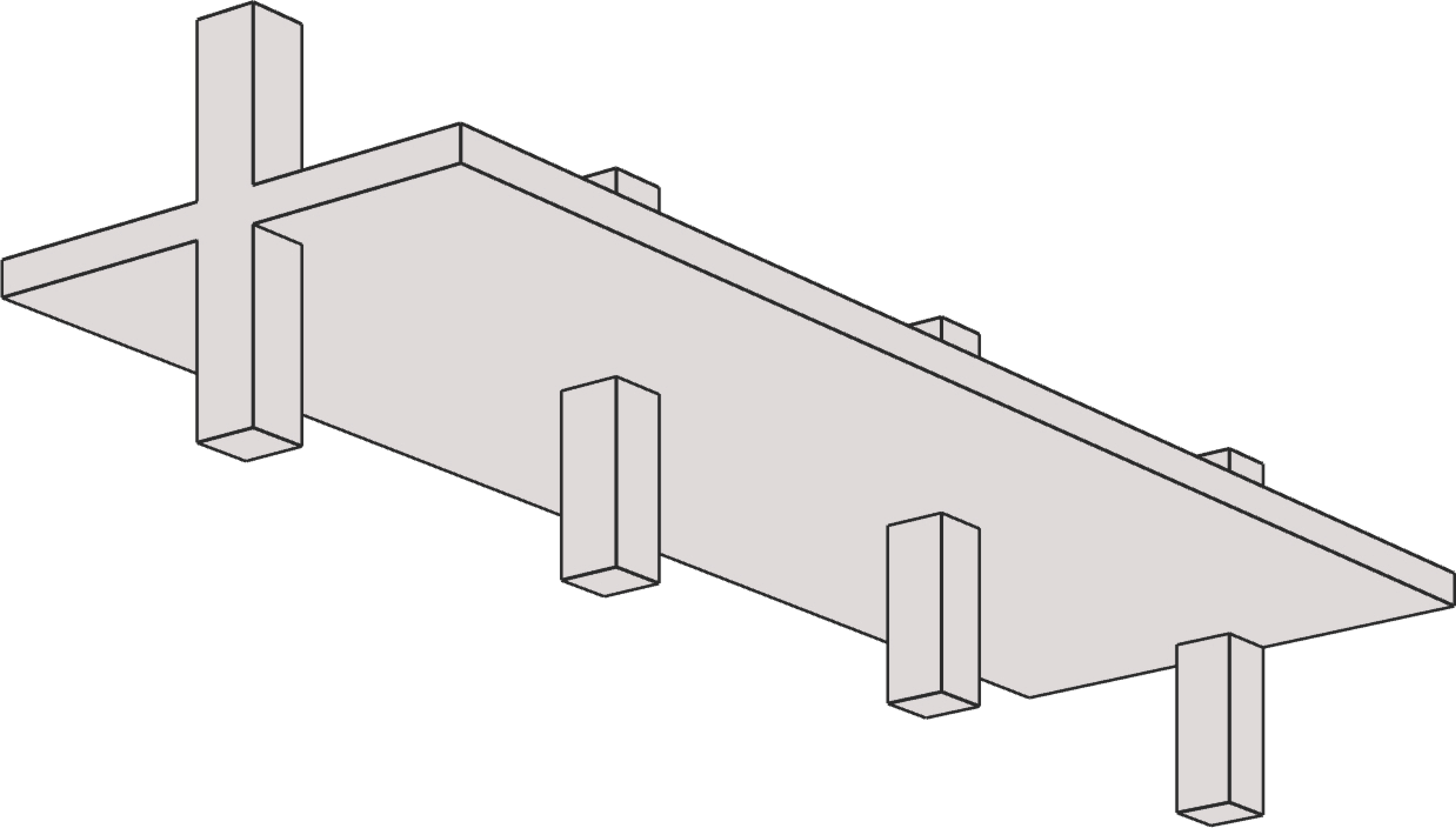
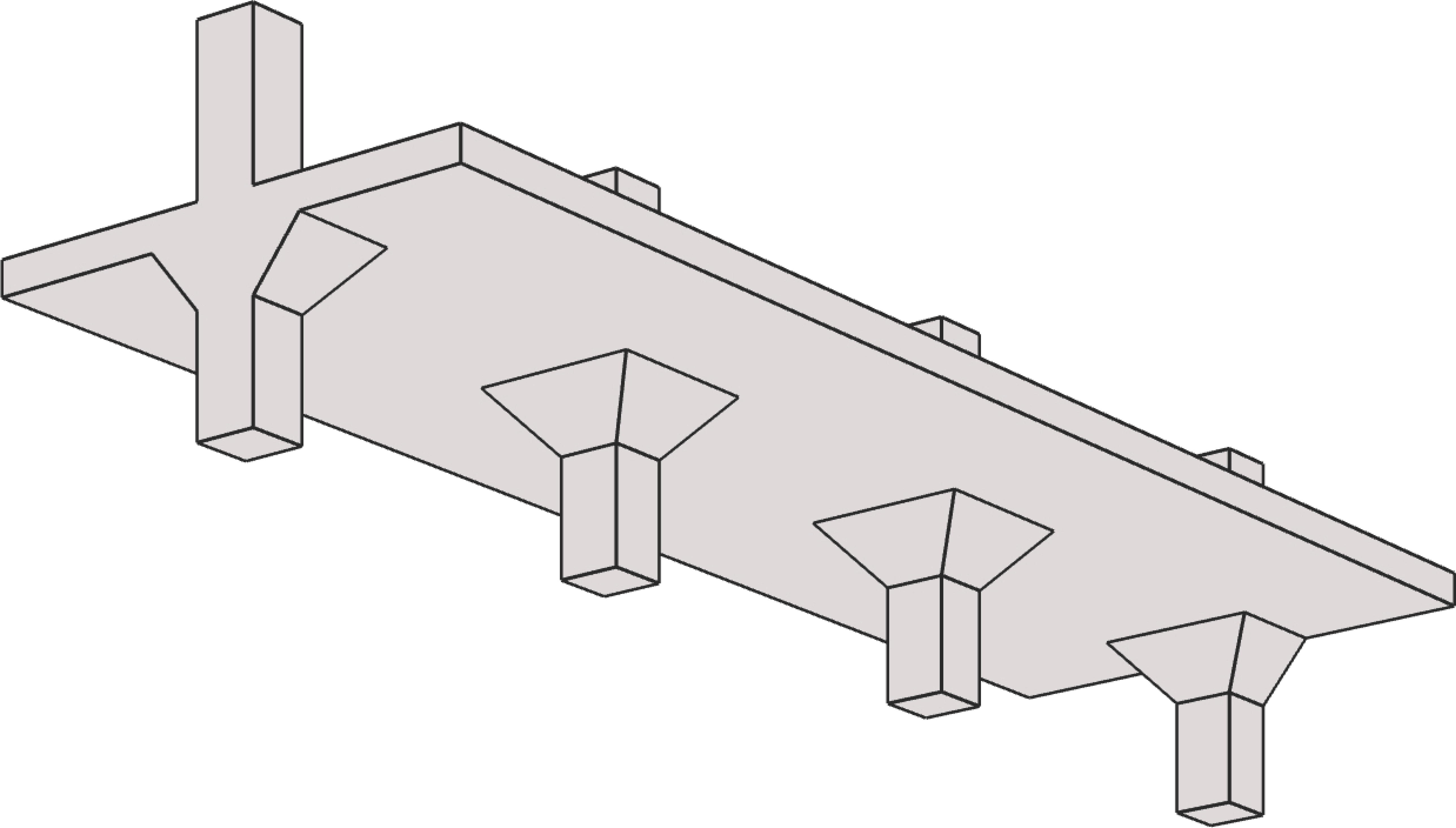
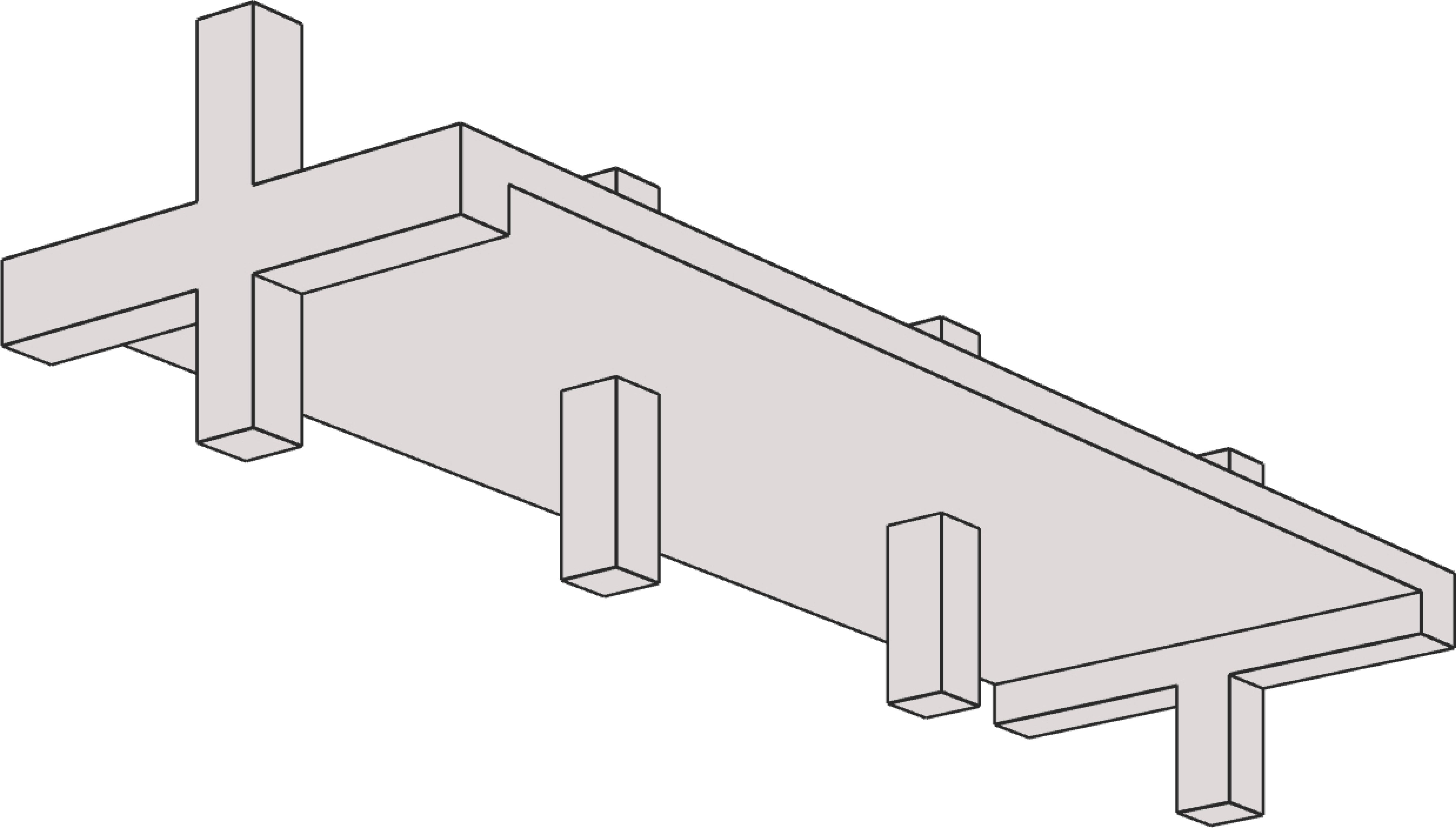
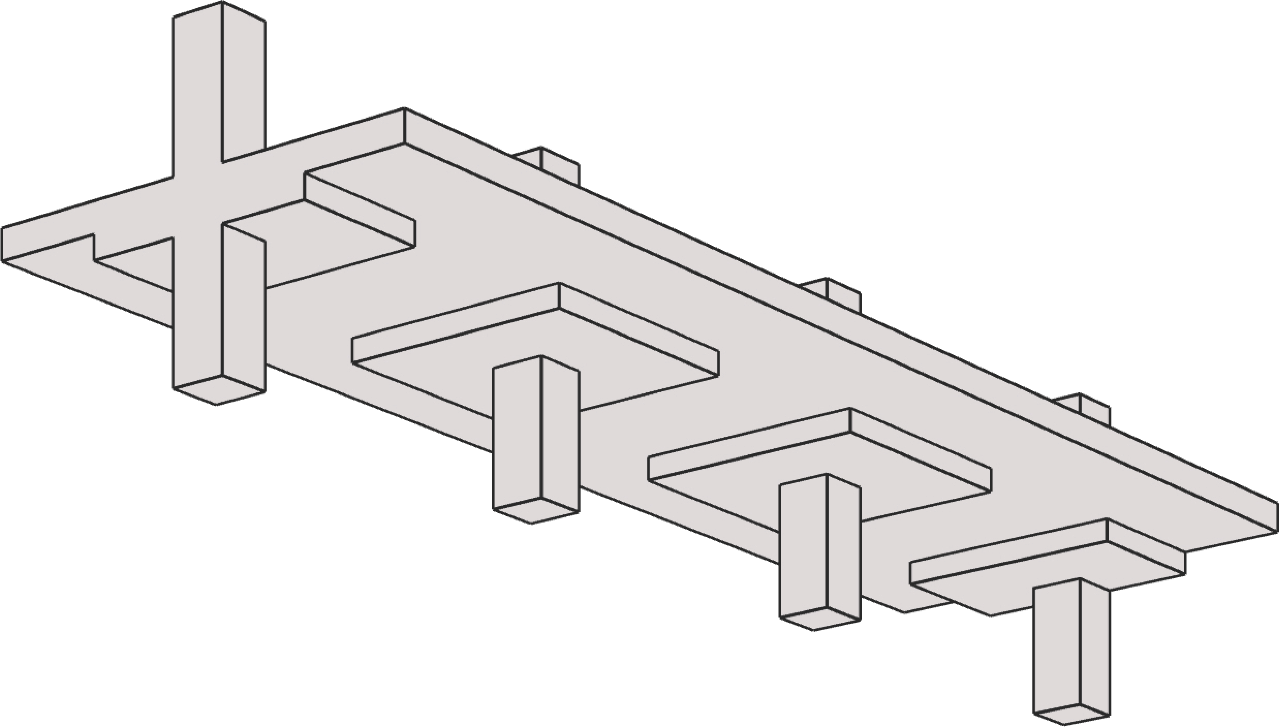
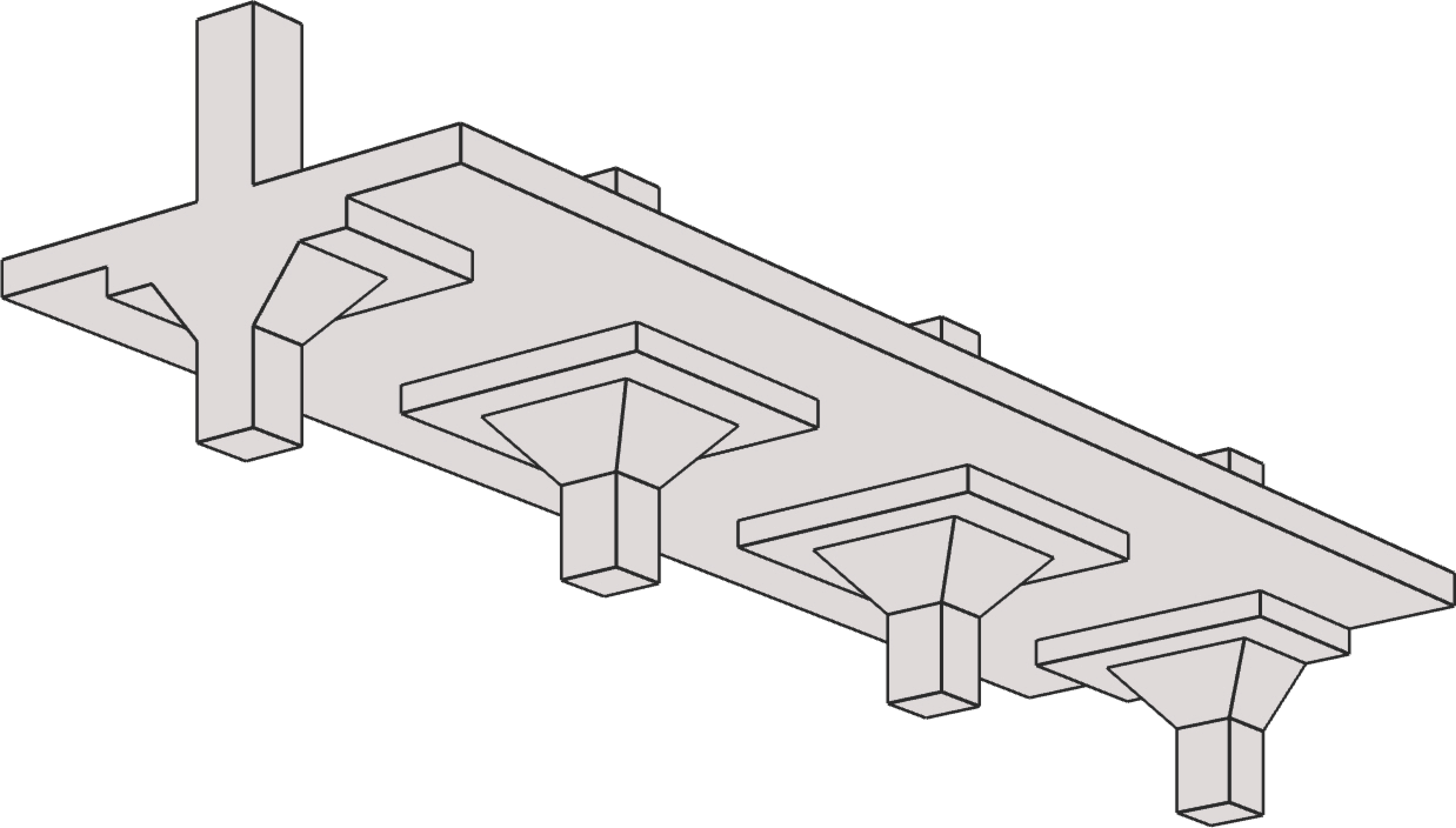
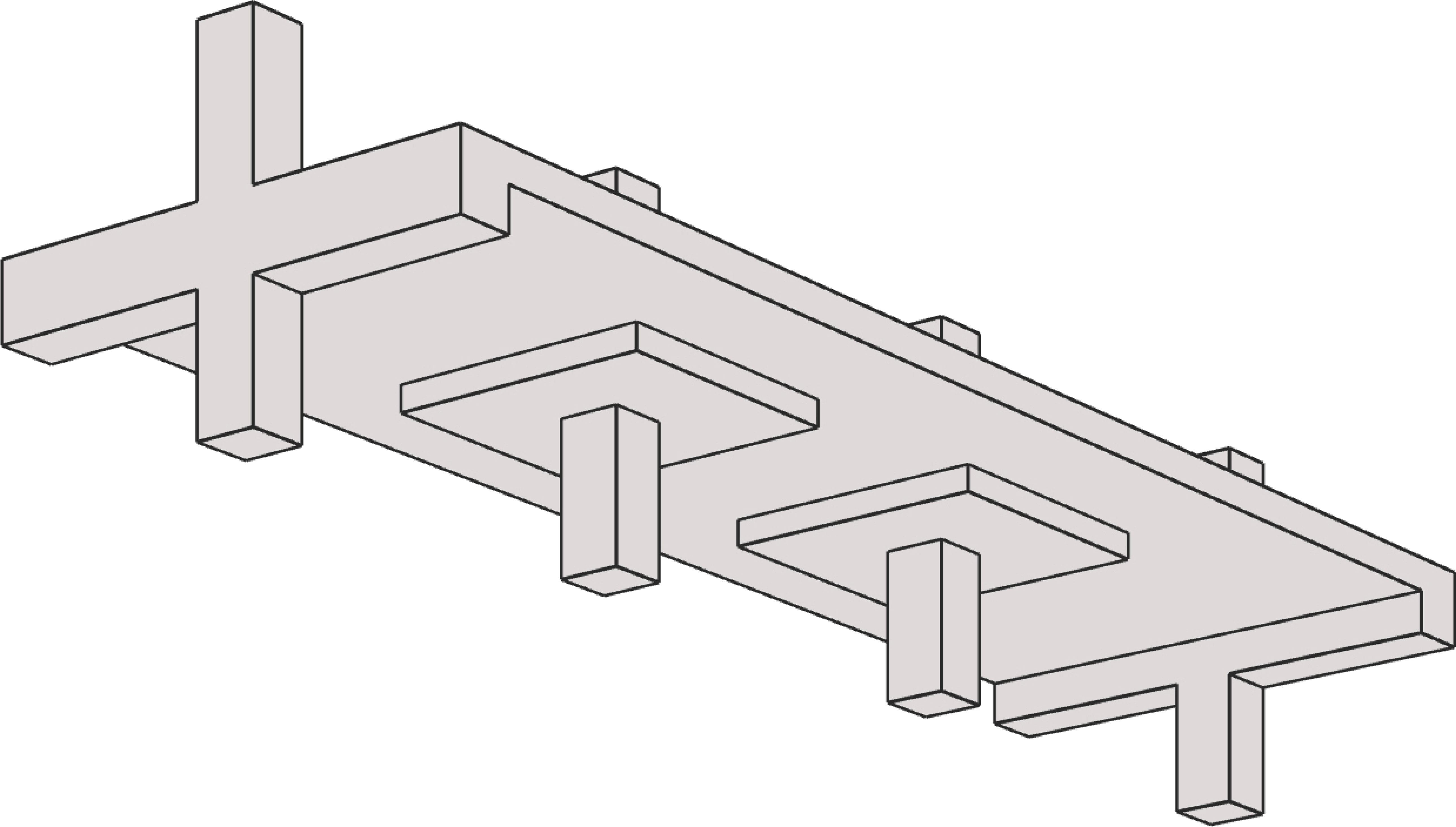
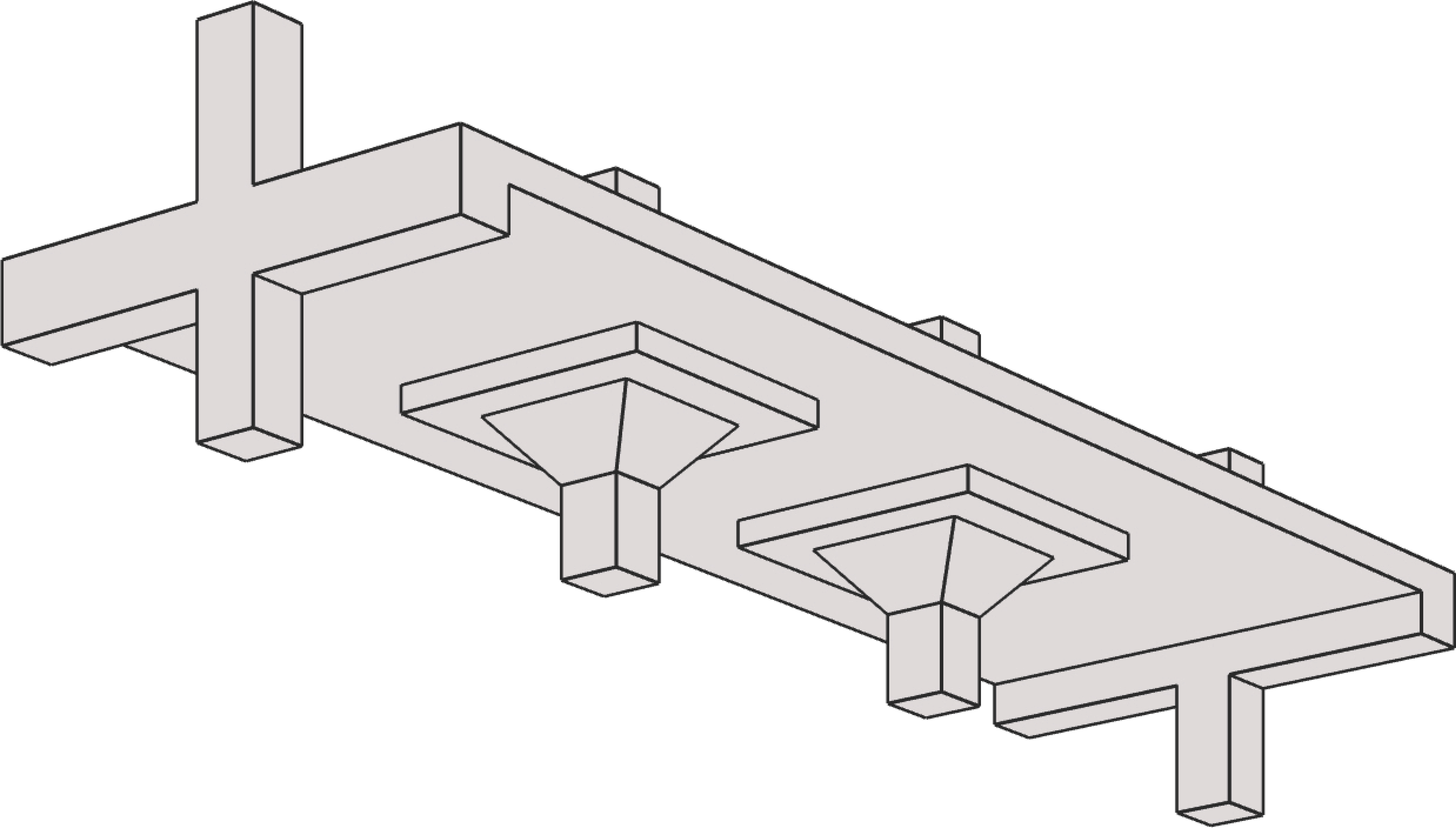
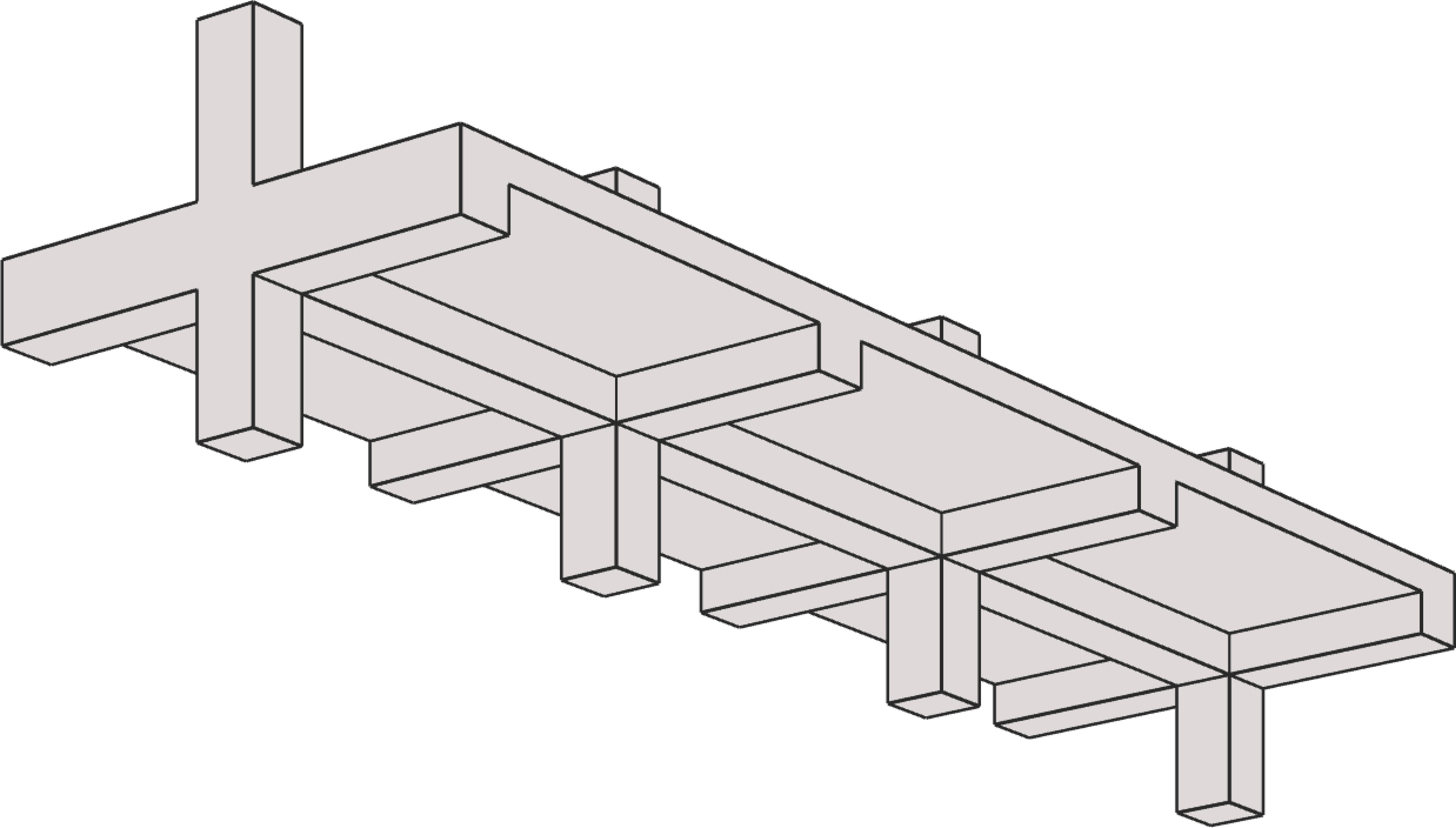
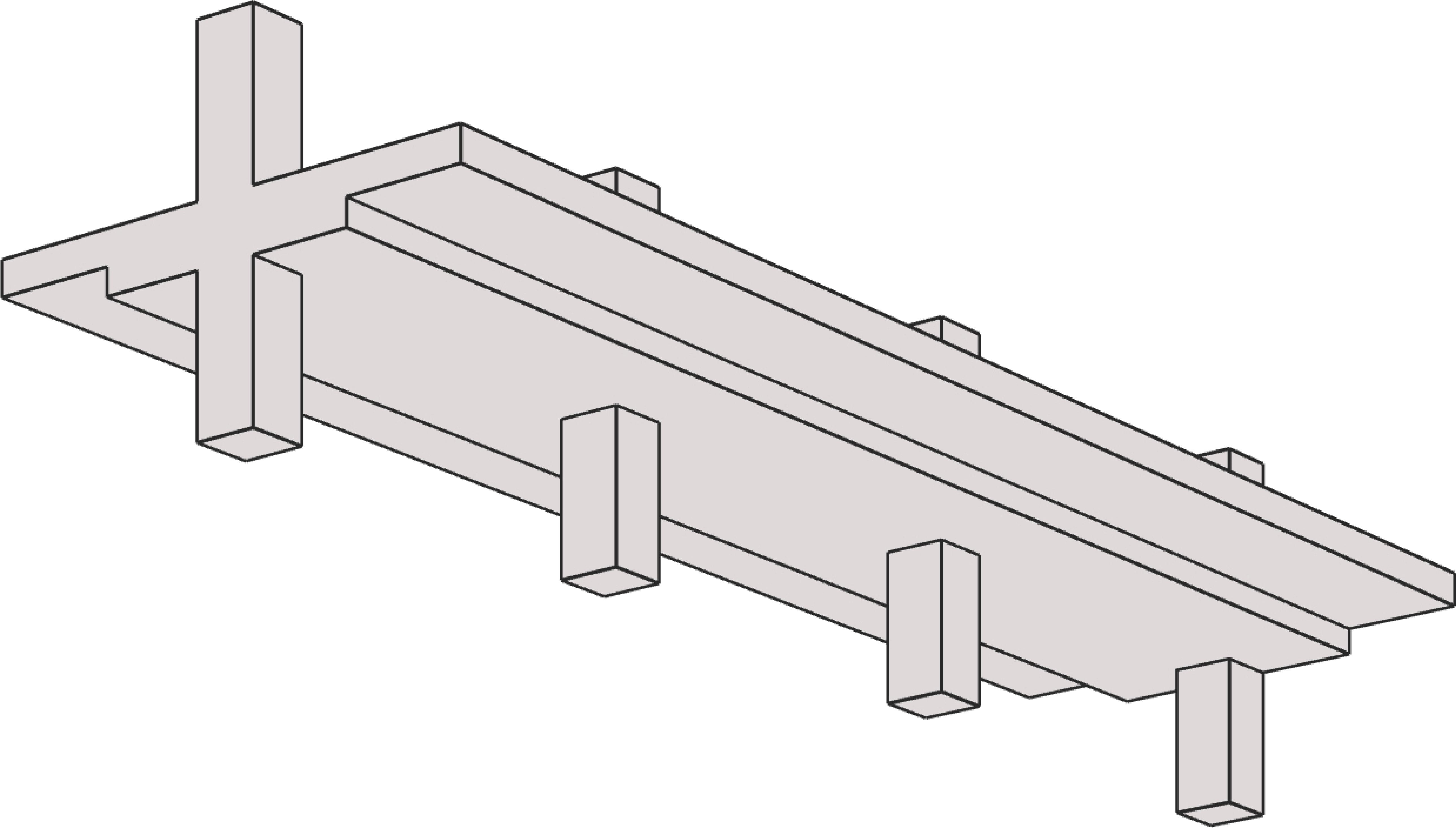
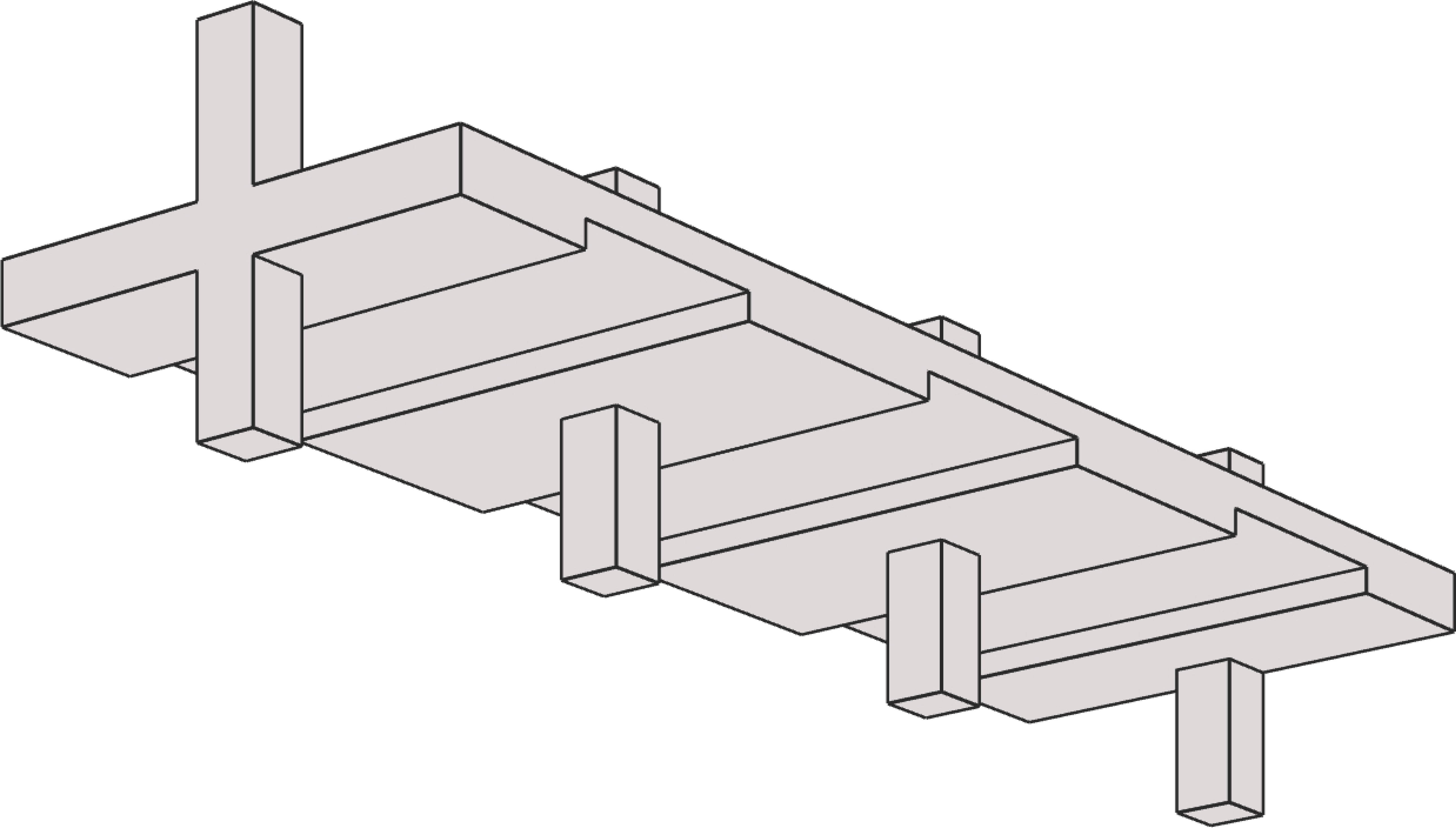
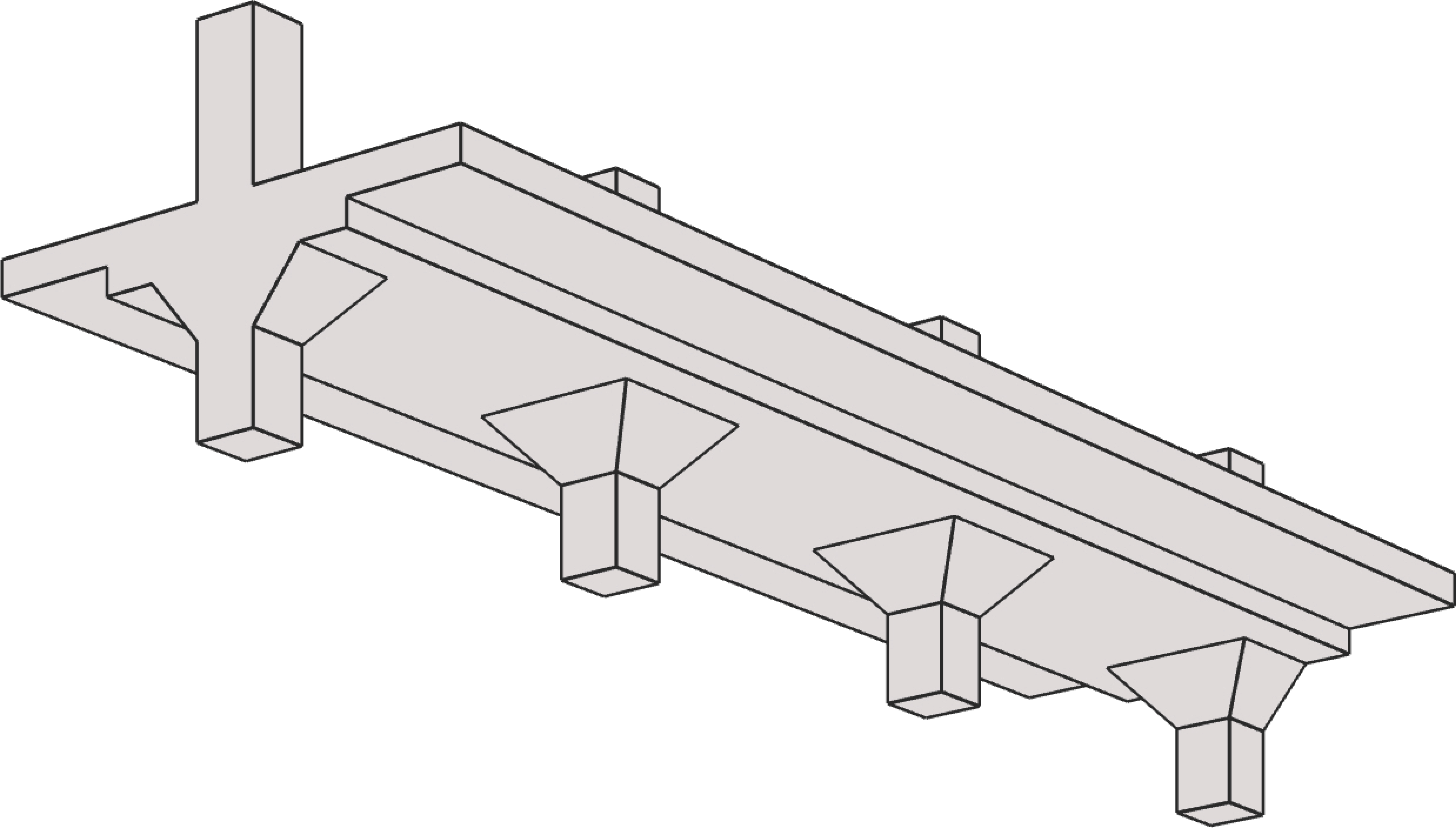
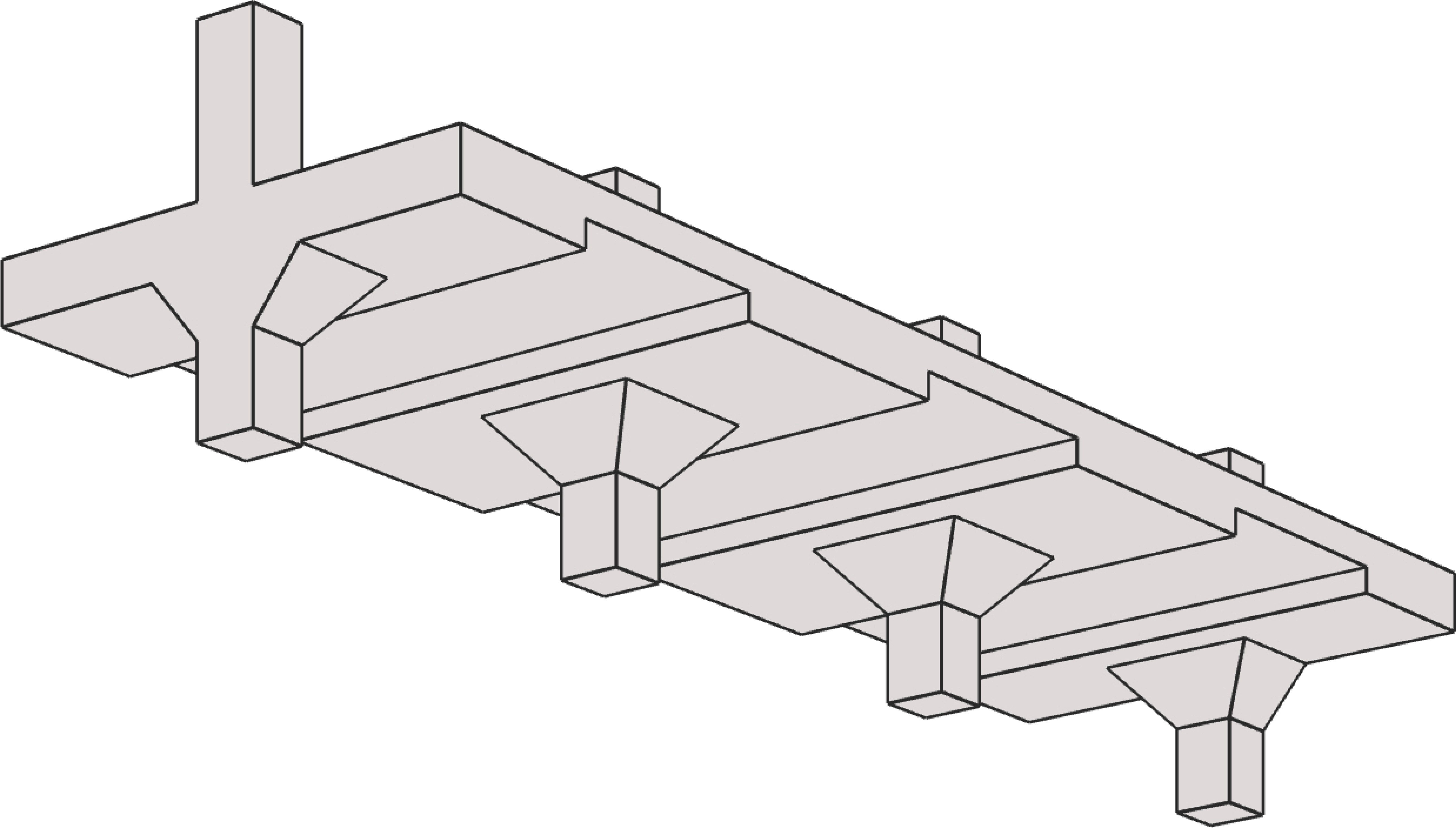
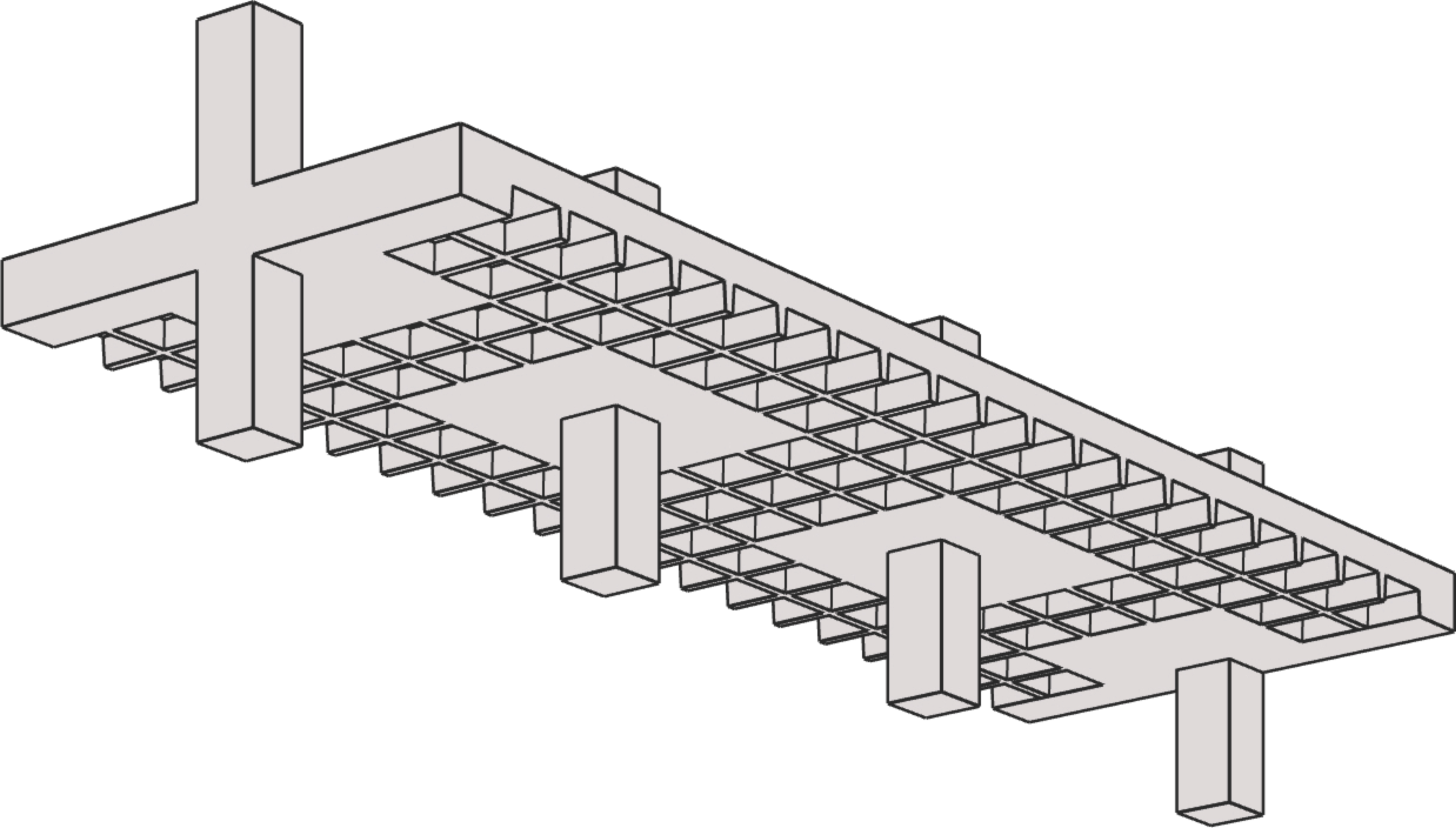
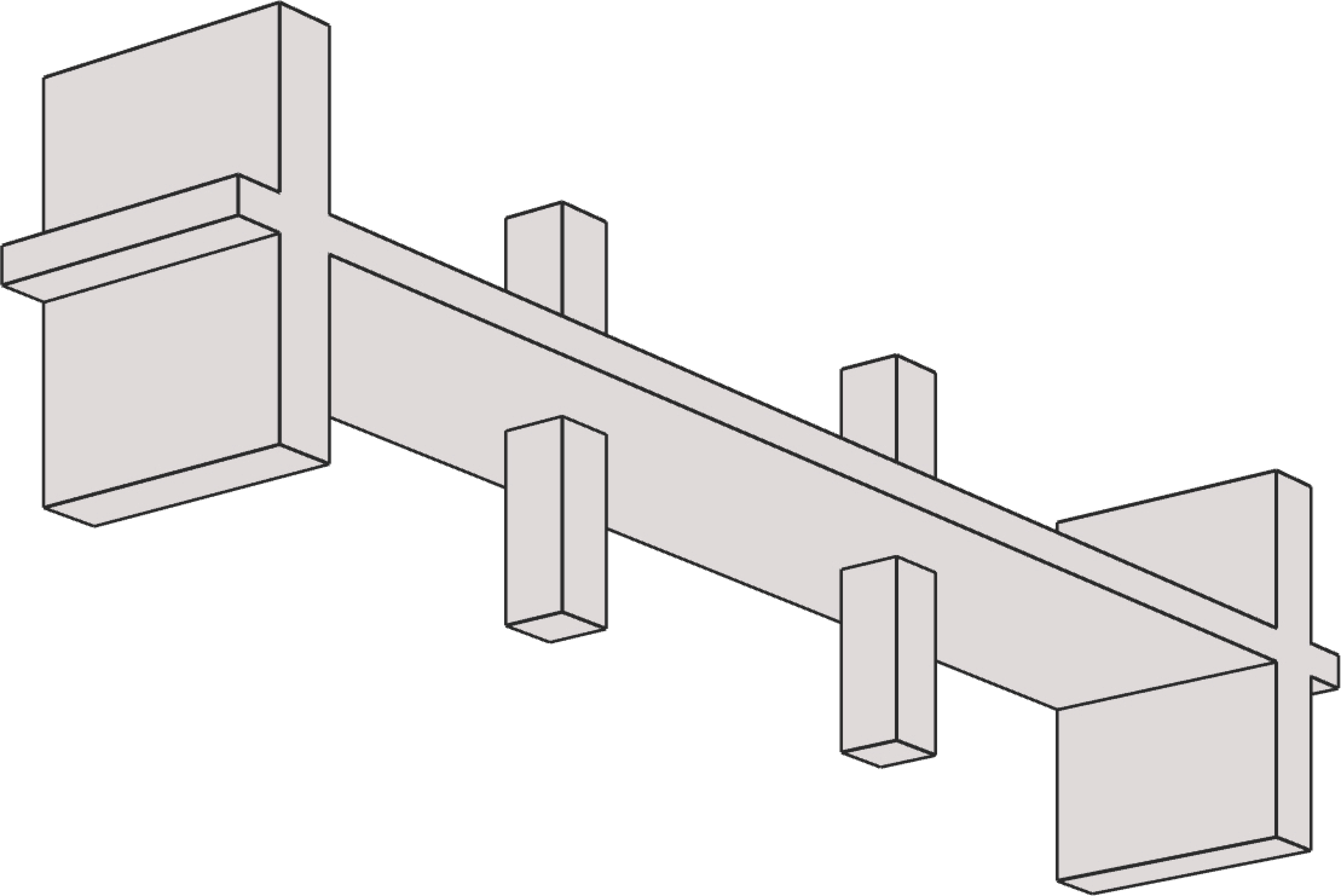
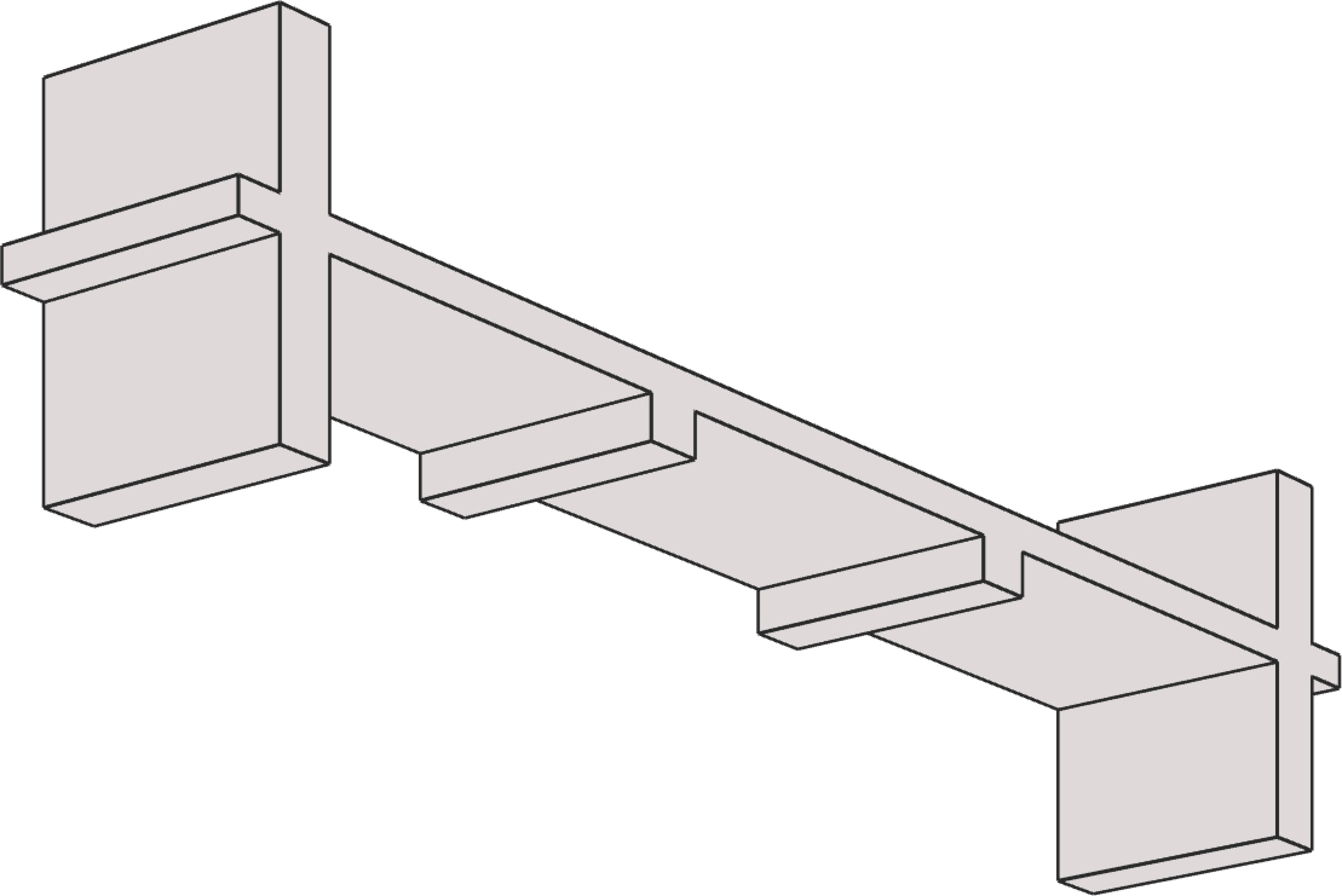
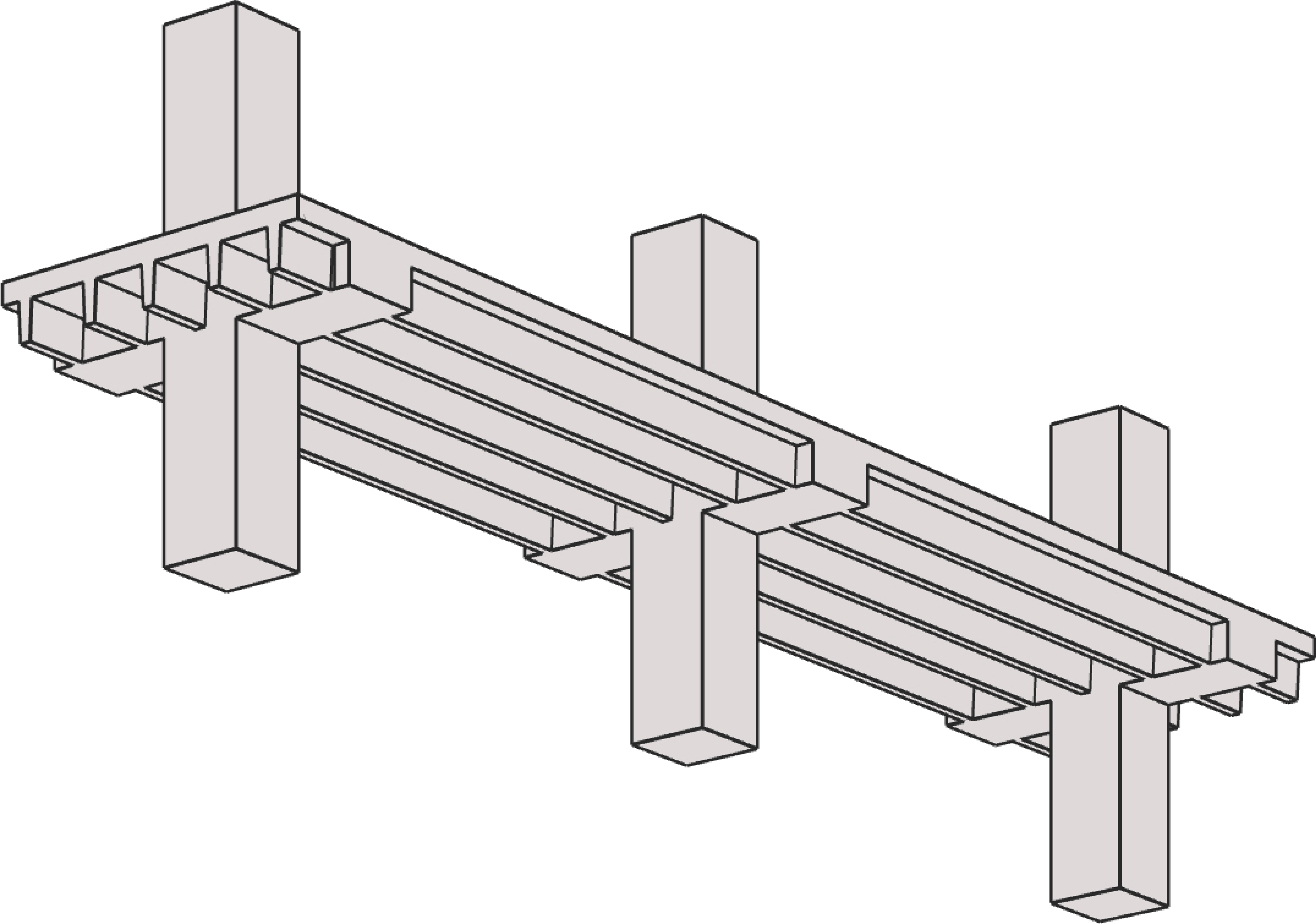
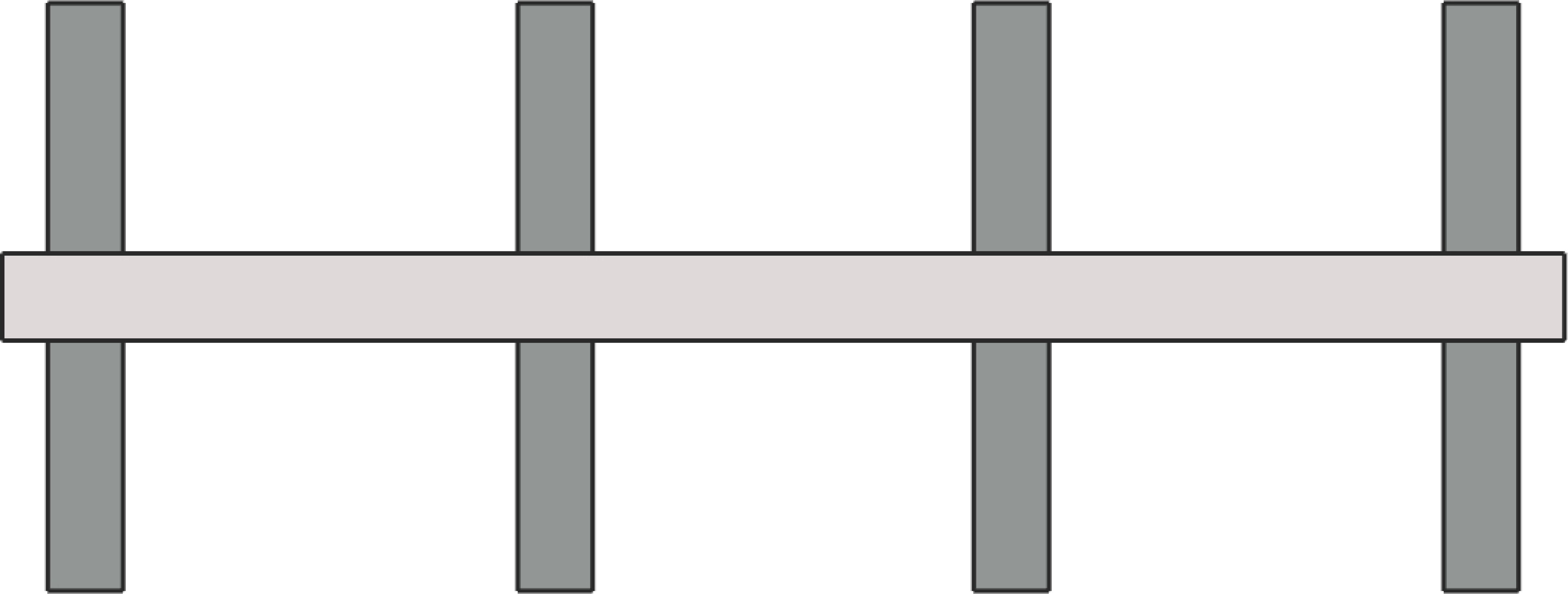
spSlab and spBeam can be used to model, analyze, and design two-way and one-way systems such as flat plate, flat slab, slab on beams, slab bands, two-way joist slab (waffle slab), one-way slab (solid slab), one-way joist slab (ribbed slab), rectangular and flanged beams. Samples of such systems are illustrated below:

Flat Plate | |
|
|
Flat Plate | with Column Capitals |
|
|
with Spandrel Beams | with Spandrel Beams & Column Capitals |
Flat Slab | |
|
|
Flat Slab | with Column Capitals |
|
|
with Spandrel Beams | with Spandrel Beams & Column Capitals |
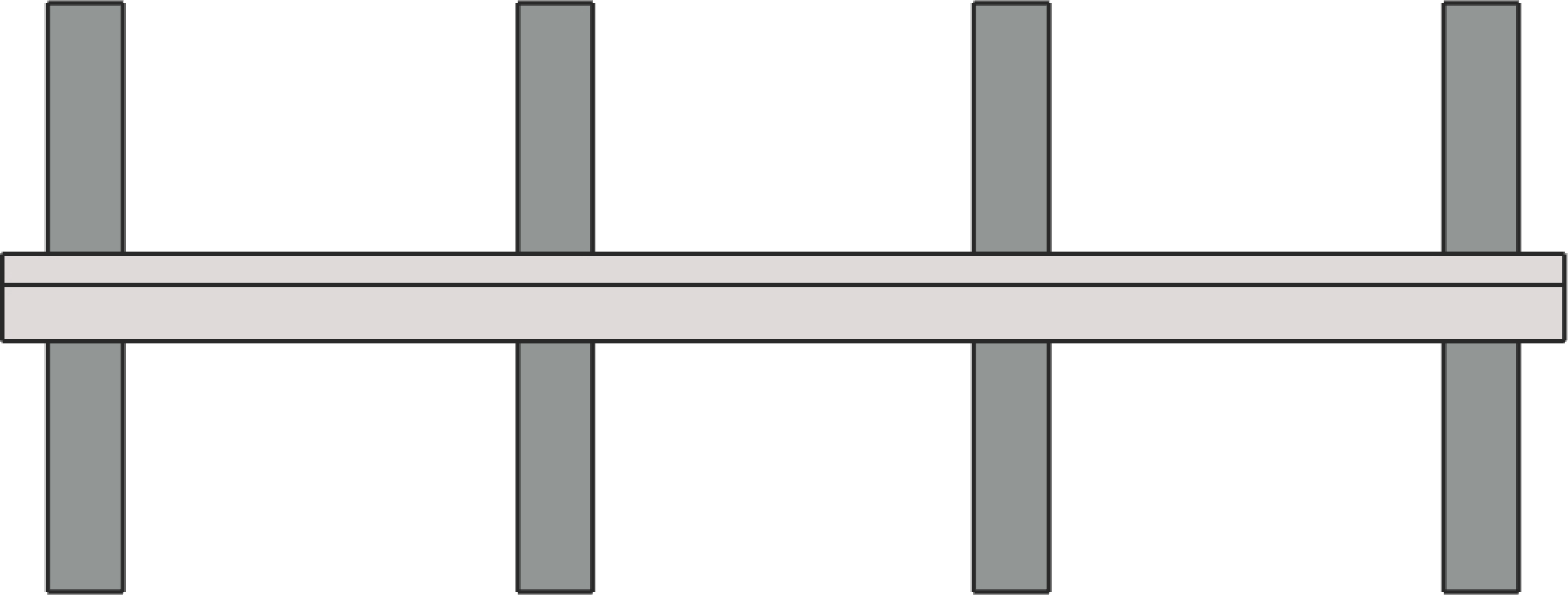
Slab on Beams | |
| |
Two-Way Beam-Supported Slab | |
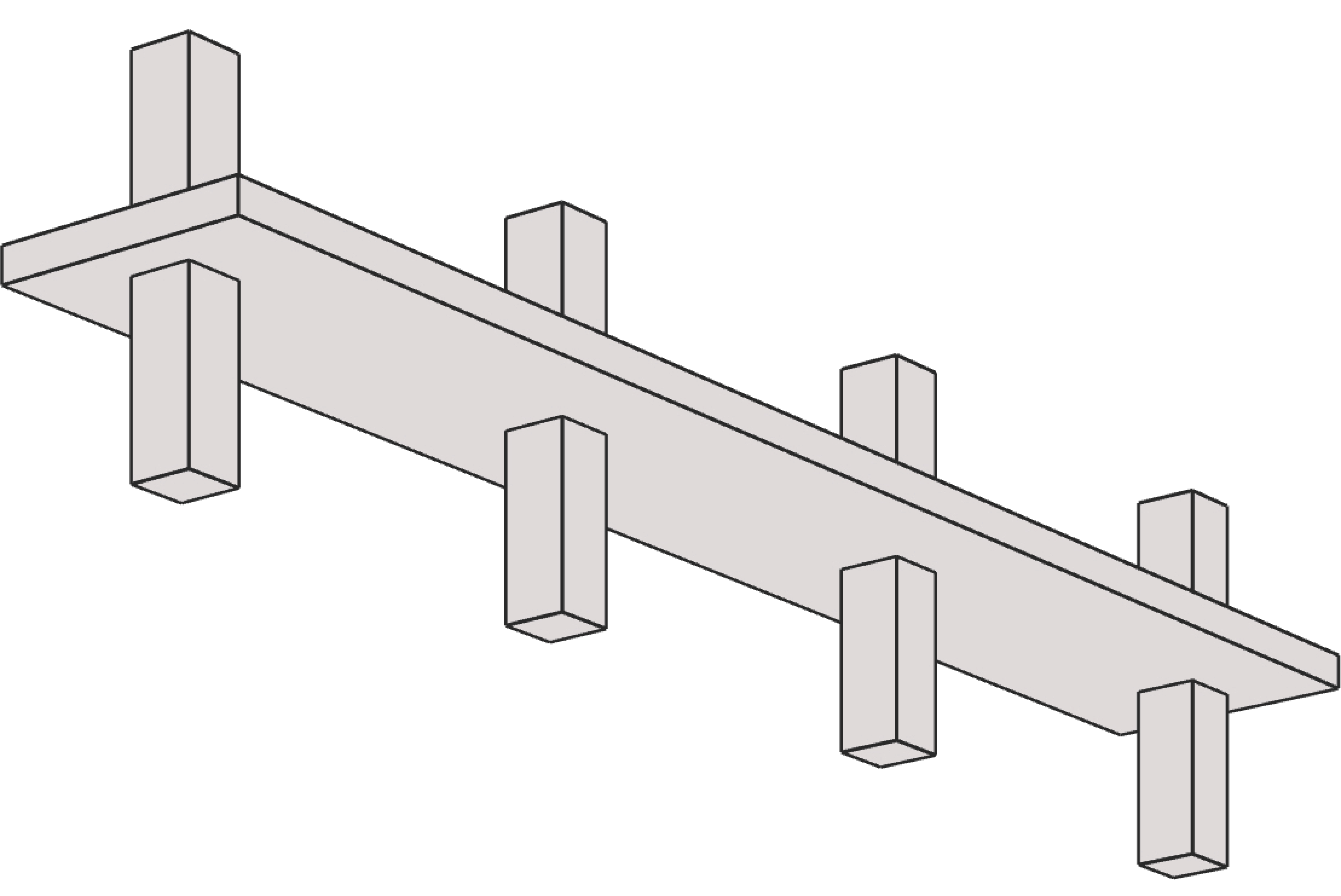
Slab Bands | |
|
|
Longitudinal Bands | Transverse Bands |
|
|
Longitudinal Bands with Column Capitals | Transverse Bands with Column Capitals |
Two-Way Joist (Waffle) | |
|
|
Waffle Slab | Waffle Slab with Column Capitals |


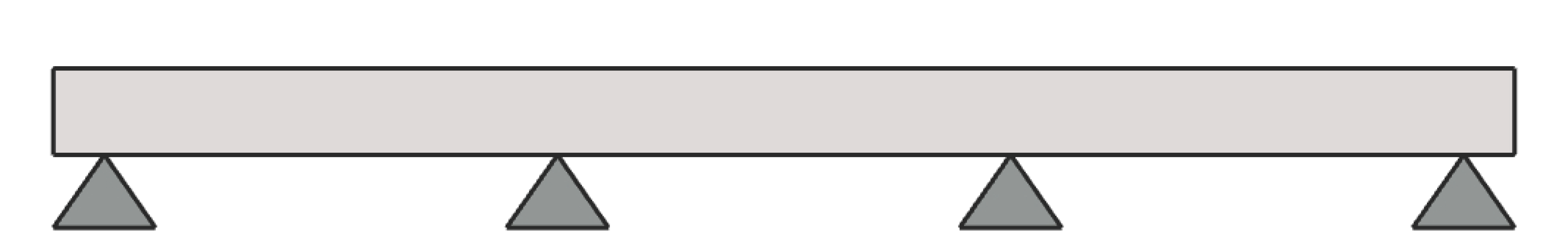
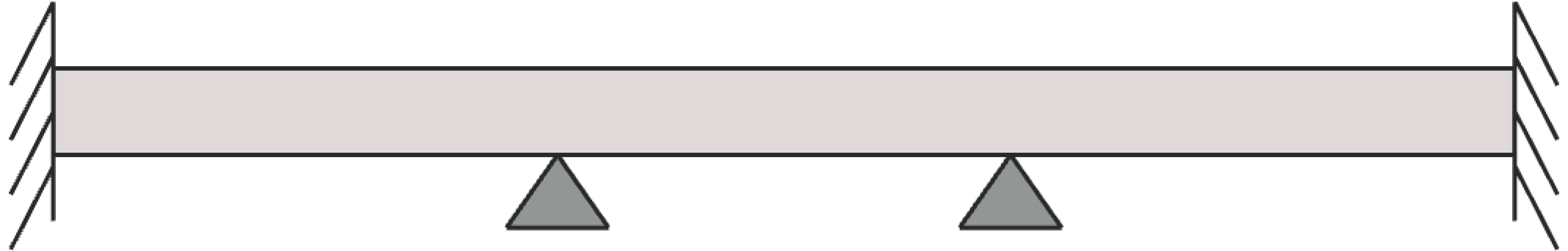
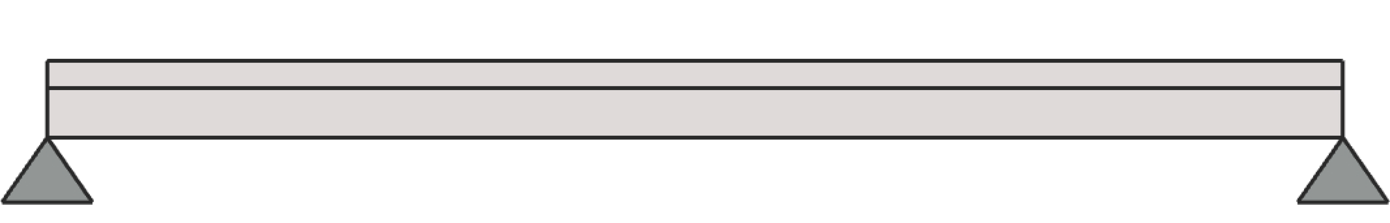
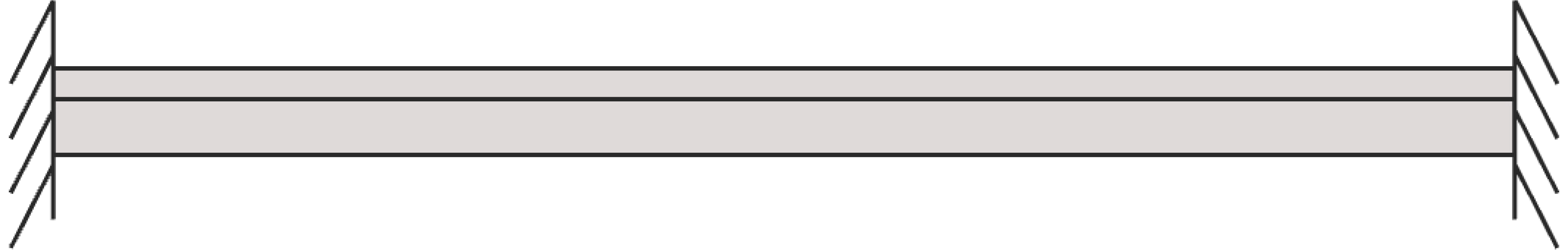
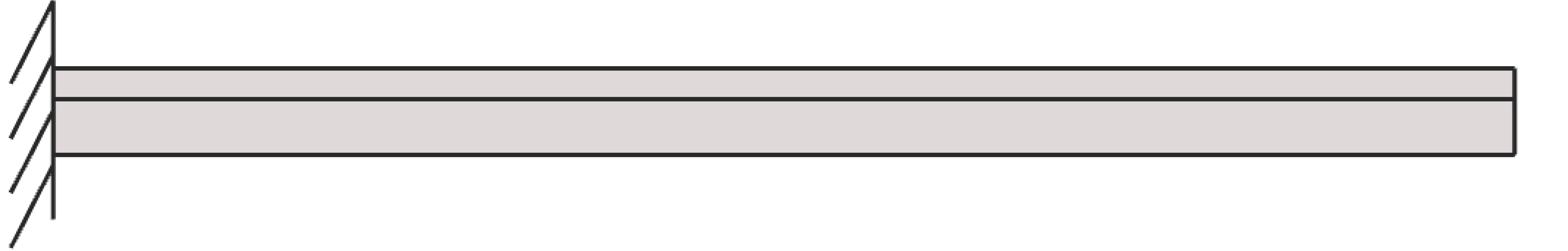
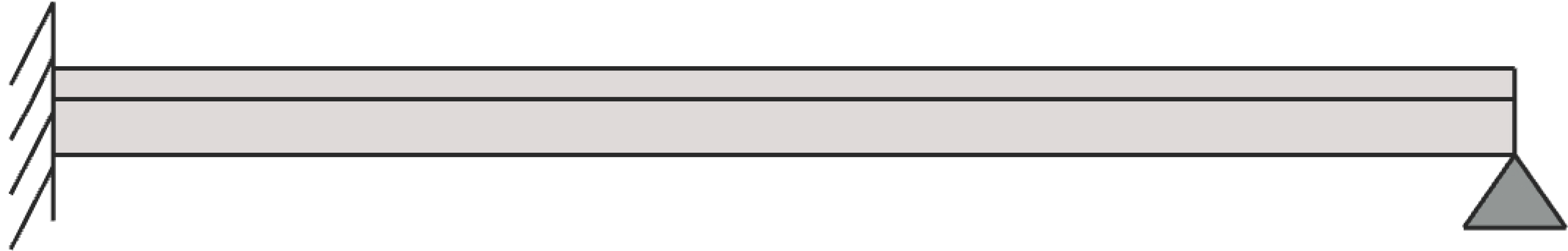
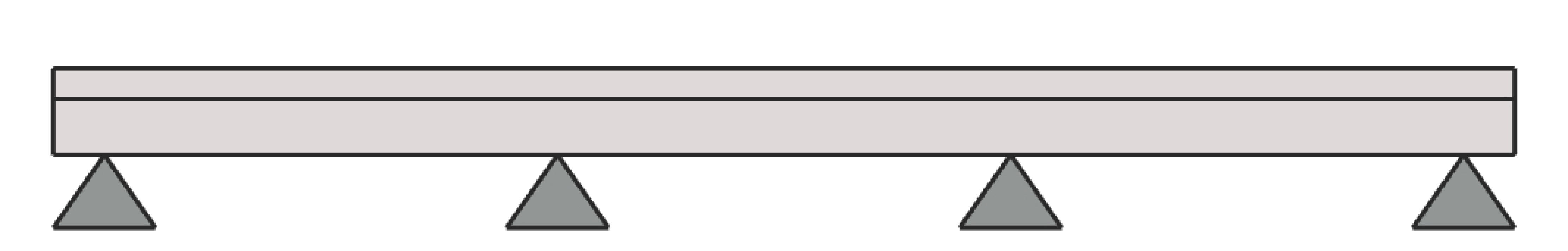
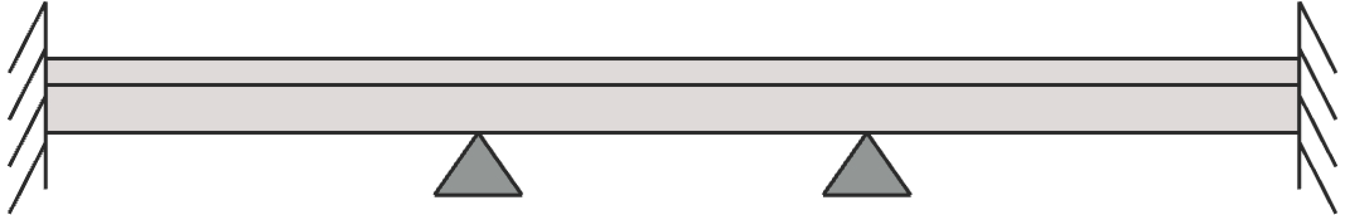
One-Way Slab (Solid) | |
|
|
Simply Supported | Fixed Ends |
|
|
Simple Cantilever | Propped Cantilever |
|
|
Continuous – Pinned Ends | Continuous – Fixed Ends |
|
|
Continuous – Column Supports | Continuous – Beam Supports |
|
|
Column Supports – End Walls | Beam Supports – End Walls |
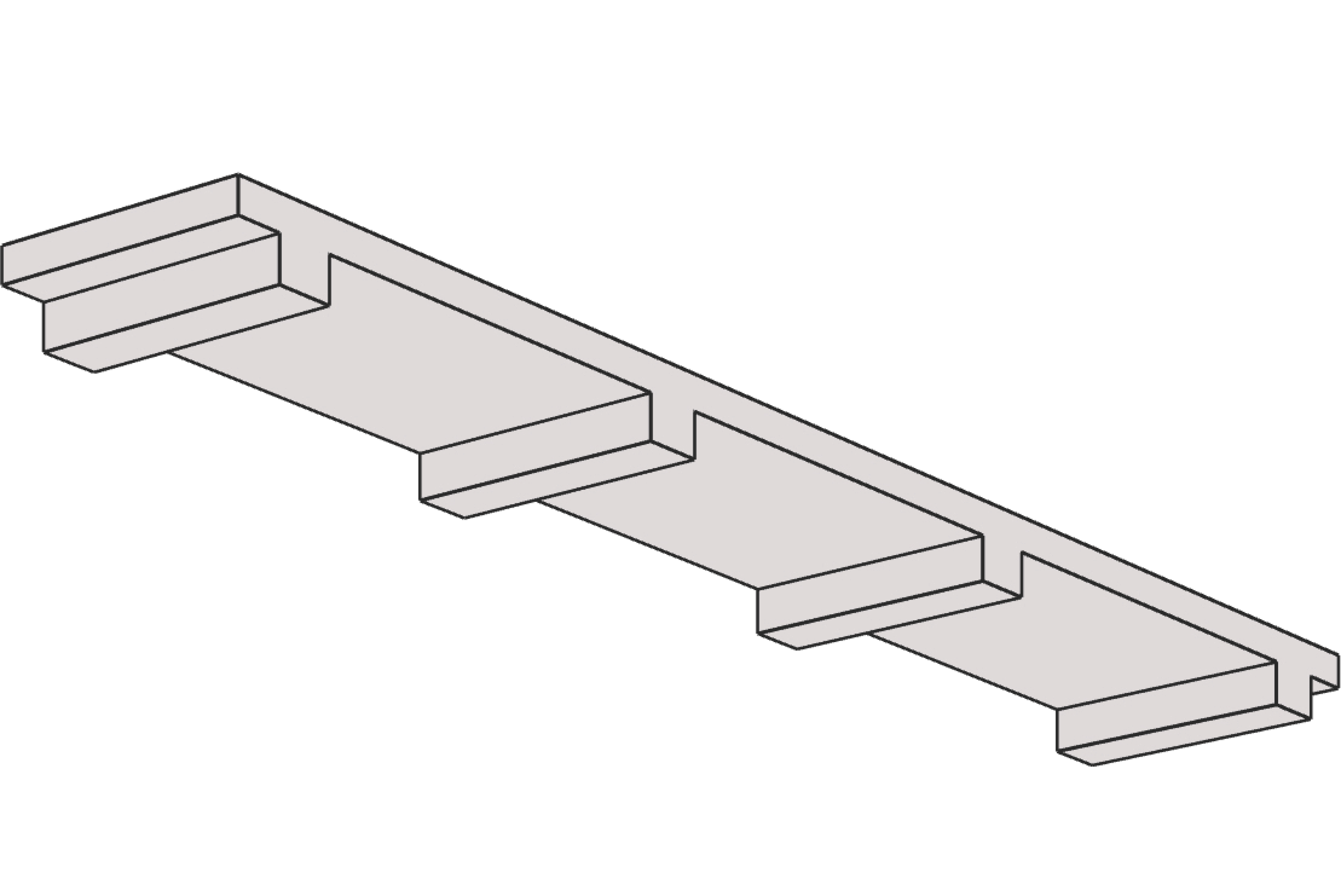
One-Way Joist (Ribbed) | |
|
|
Joist-standard Module | Joist-wide Module |
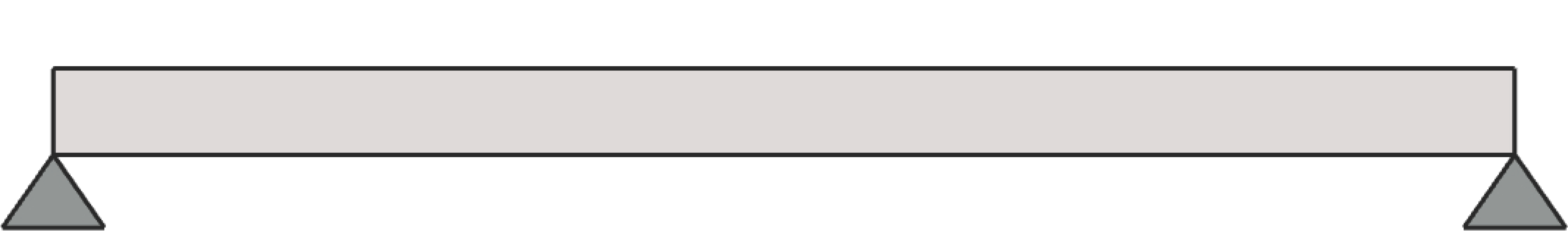
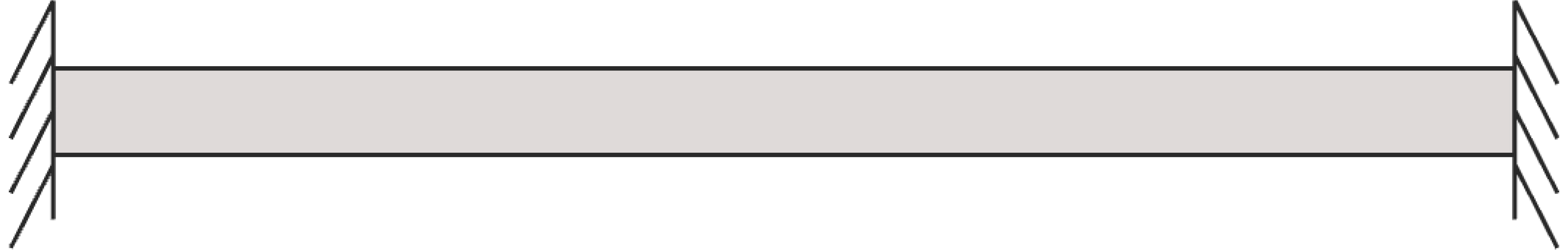
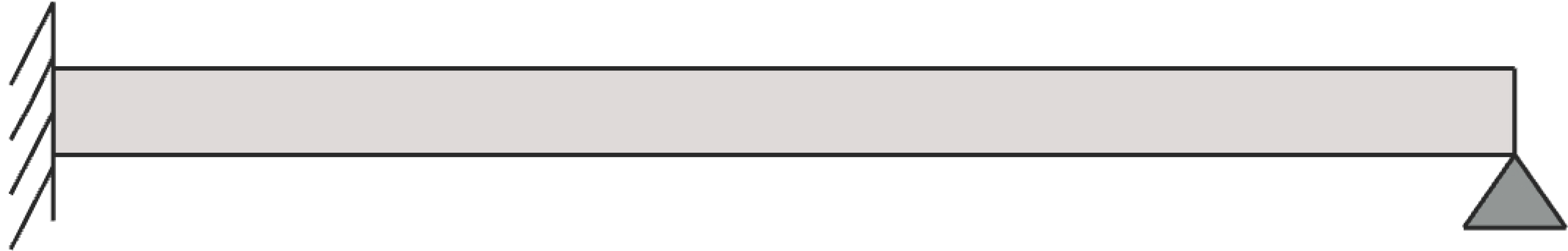
Rectangular Beams | |
|
|
Simply Supported | Fixed Ends |
|
|
Simple Cantilever | Propped Cantilever |
|
|
Continuous – Pinned Ends | Continuous – Fixed Ends |
| |
Continuous – Column Supports | |
Flanged Beams | |
|
|
Simply Supported | Fixed Ends |
|
|
Simple Cantilever | Propped Cantilever |
|
|
Continuous – Pinned Ends | Continuous – Fixed Ends |
| |
Continuous – Column Supports | |


The top-surface of the slab/beam lies in the XY plane of the right-handed XYZ rectangular coordinate system shown in Figure 2.1. The slab thickness (and/or beam depth) is measured in the direction of the Z-axis. When looking at the screen, the positive X-axis points horizontally to the right on the screen, the positive Y-axis points directly out of the screen towards you, and positive Z-axis points vertically downwards on the screen. Thus, the XY plane is defined as being in the plane of the screen. Note that the loads shown in the figure are all positive and may not match the typical sign conventions. More details related to Span Loads can be found in Section 5.2.4.3.
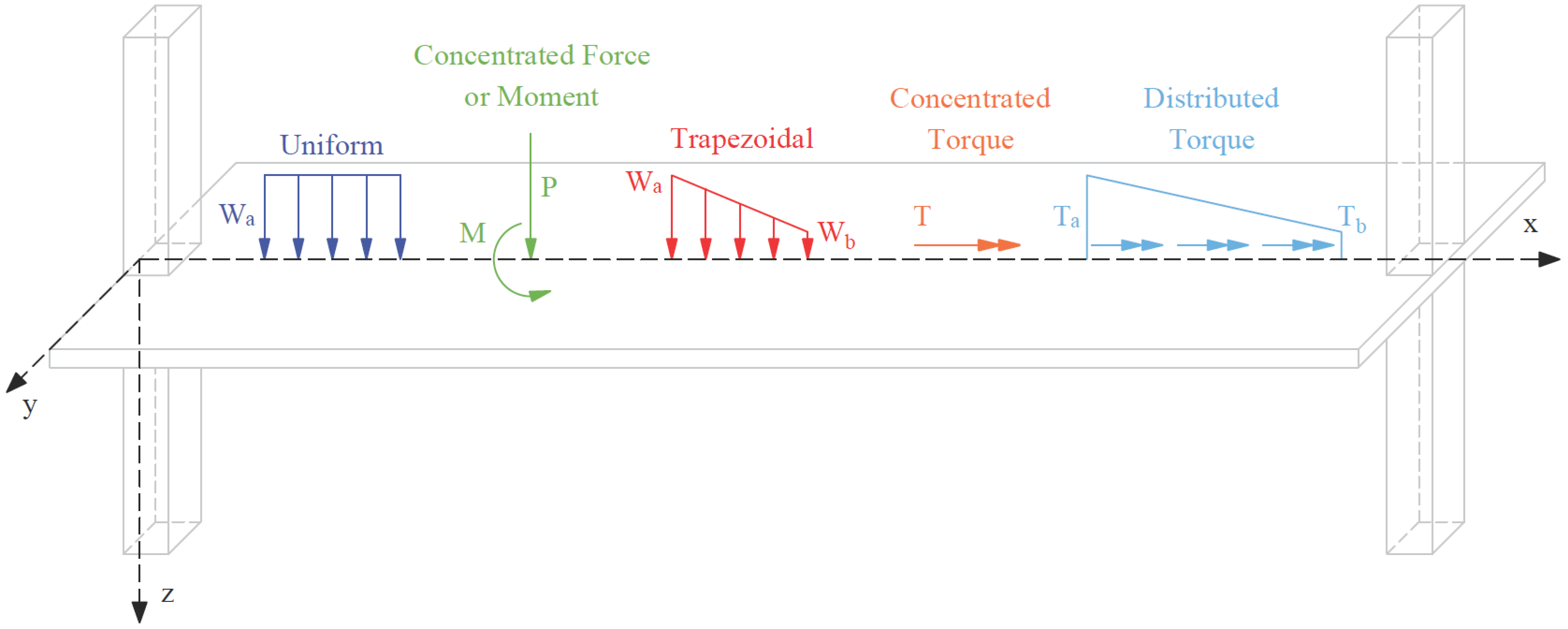
Figure 2.1 - Coordinate System
Consistent with this sign convention, the tabular results in the program output such as reinforcement values are presented for each span, beginning with the zero value of the X coordinate referred to as the Left zone and working towards the full span length in the X direction also designated as the Right zone. between the Right and Left zones of a span is the Midspan zone represents commonly important values from the structural analysis and design.
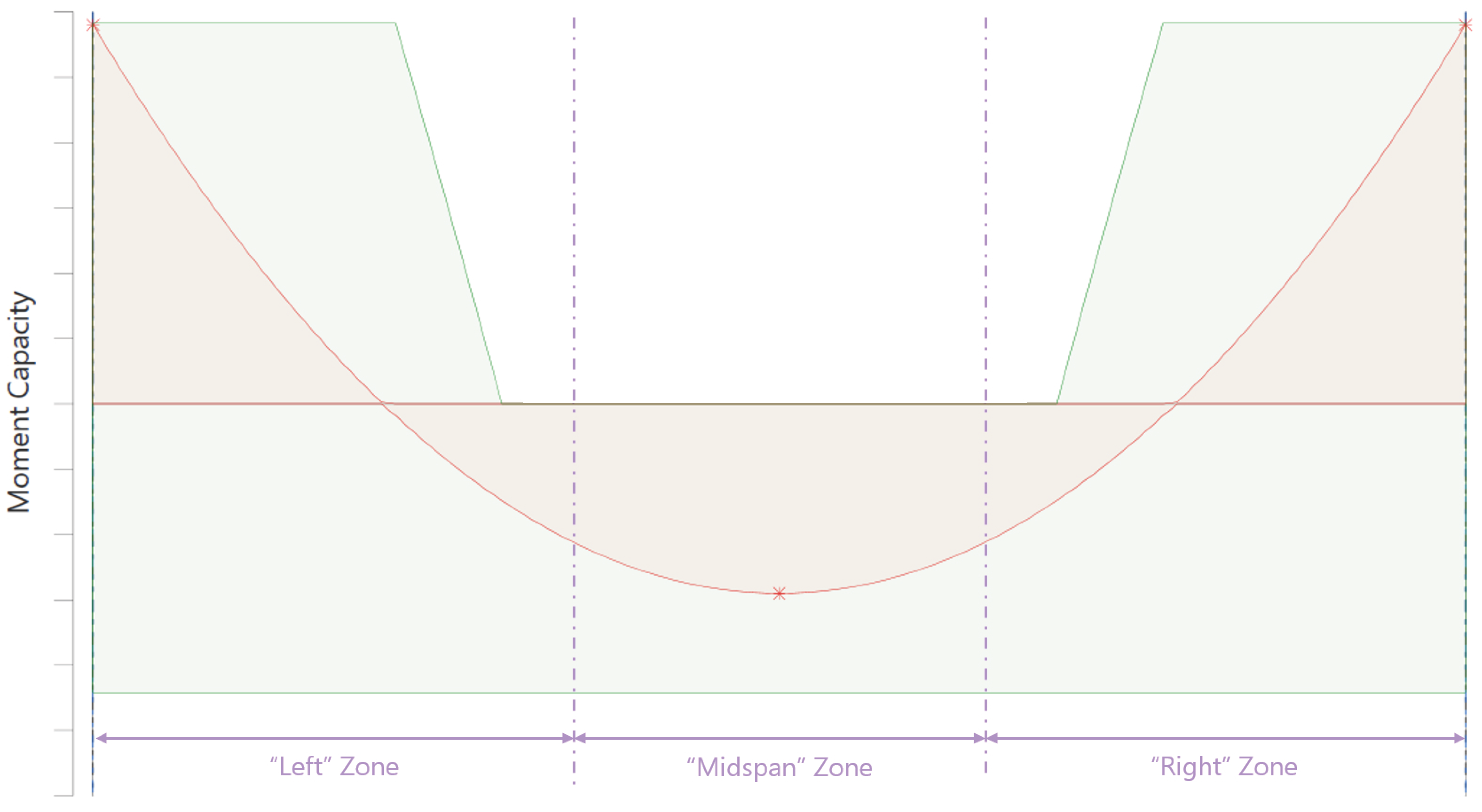
Figure 2.2 - Result Output Sign Convention
As a result of the coordinate system described above, results output is presented as follows for shear force diagram, bending moment diagram, and torsion force diagram.
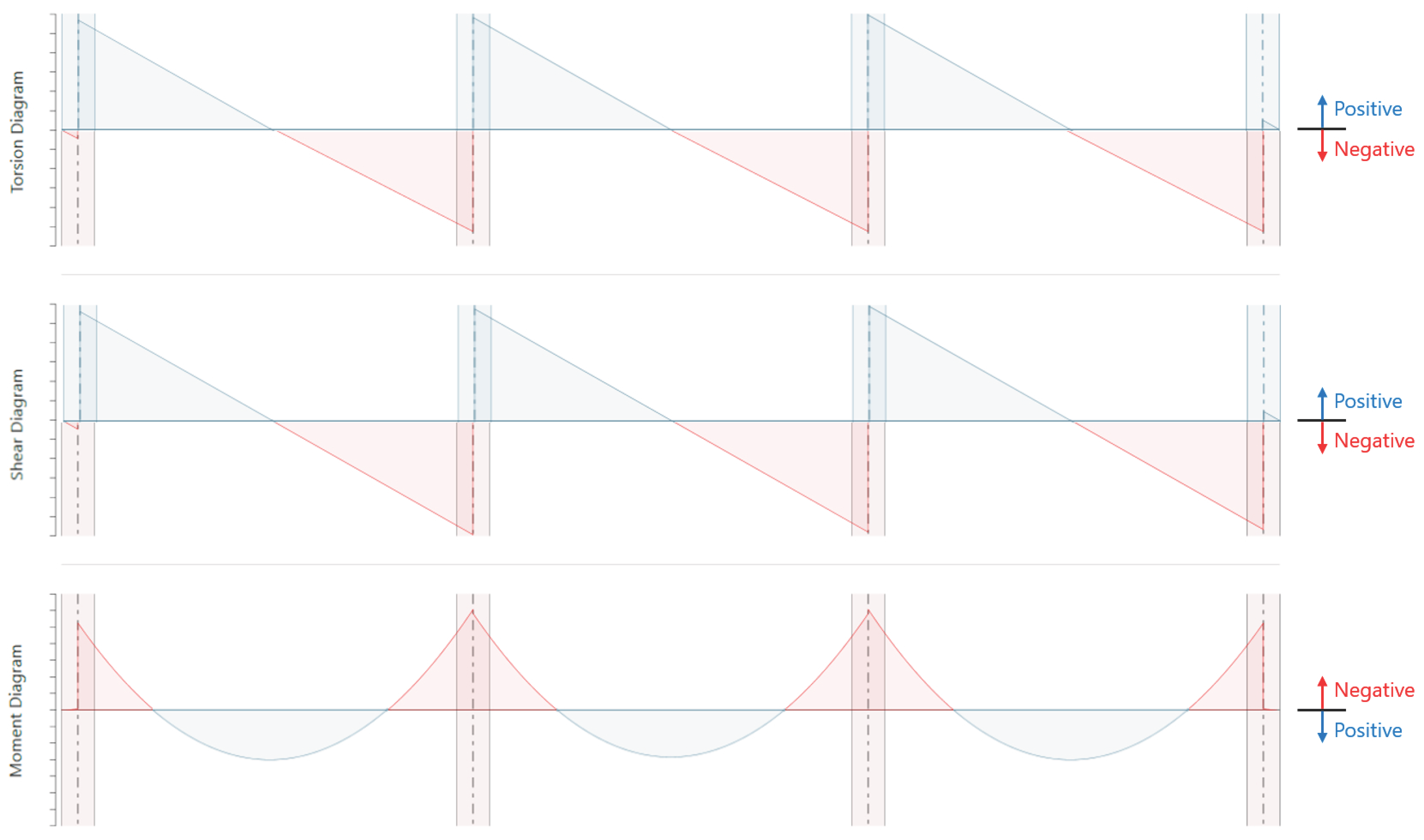
Figure 2.3 - Result Output Sign Convention