spColumn is widely used for design and investigation of columns, shear walls, bridge piers as well as typical framing elements in buildings and structures including foundation piles and caissons. Equipped with the latest American (ACI 318) and Canadian (CSA A23.3) Concrete codes, spColumn is developed to design and investigate any reinforced concrete sections subject to combined axial and flexural loads. In sway and non-sway frames, spColumn can analyze second order (P-Delta) effects using the moment magnification method when slenderness considerations are required.
Formerly pcaColumn, PCACOL, and IrrCOL, spColumn investigates sections that are impossible to find on design charts or to do by hand. The section can be rectangular, round or irregular, with any reinforcement layout or pattern. The program offers investigation of irregularly shaped, reinforced concrete column sections that may contain one or more solids and openings. Top selling worldwide, spColumn provides a full featured 3D visualization of the nominal and factored failure surface. Import/export DXF files, nominal interaction diagrams, and display of capacities at your load point are just a few of the rich program features.
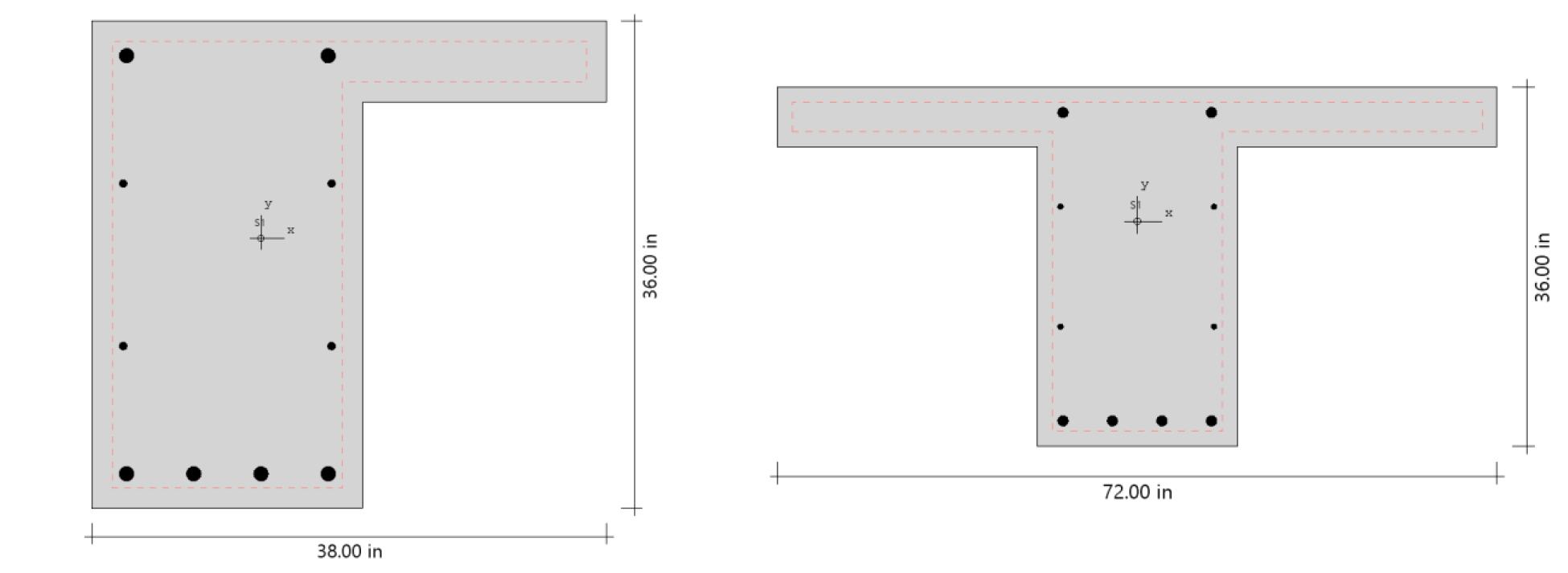
spColumn can be used to model, analyze, and design column systems based on slenderness, loading, shape, reinforcement layout, confinement type, or application such as building columns, shear walls, bridges, piers / pilaster, sound walls, architectural columns and beams. Samples of such systems are illustrated below.
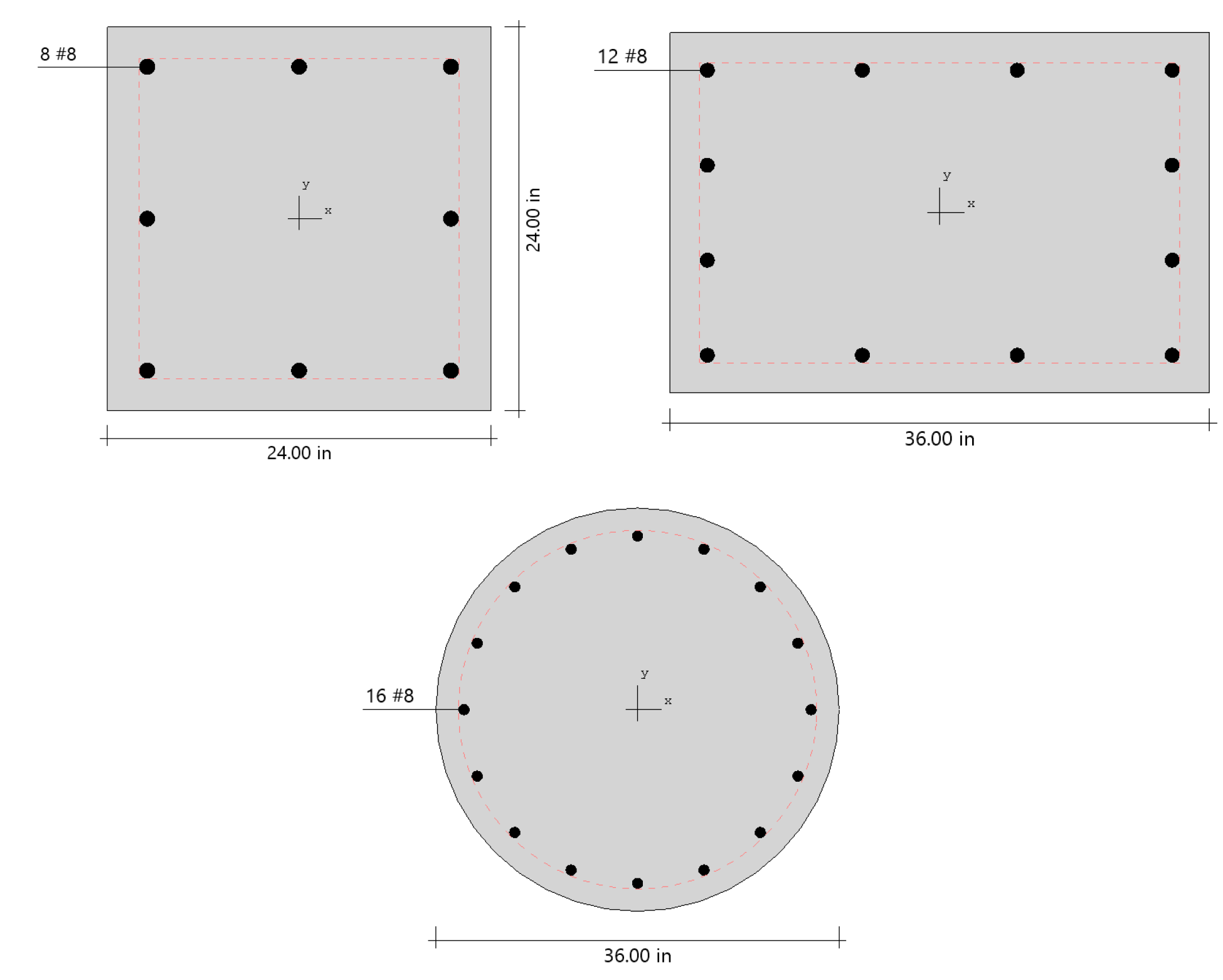
Building Columns
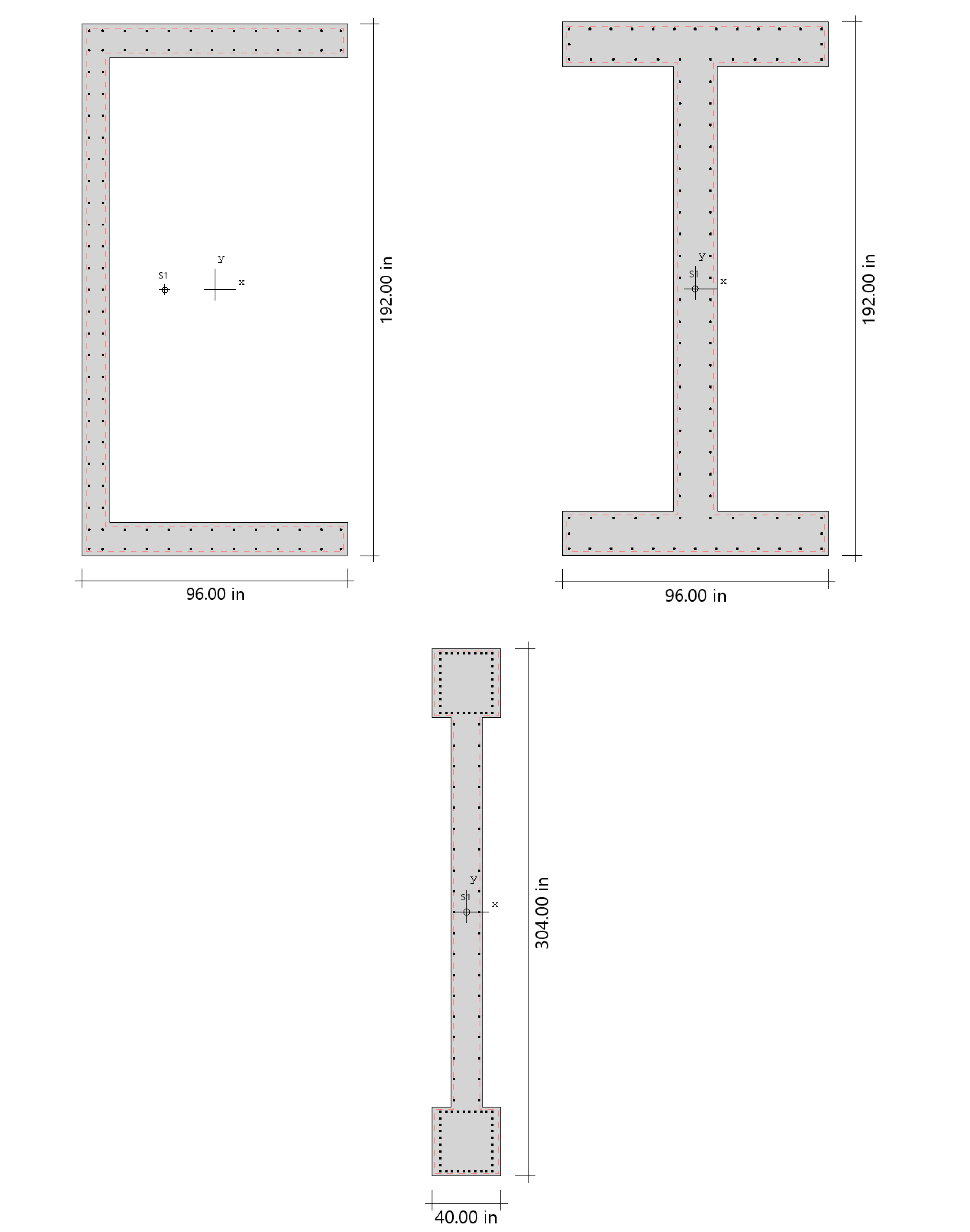
Shear Walls
Bridges
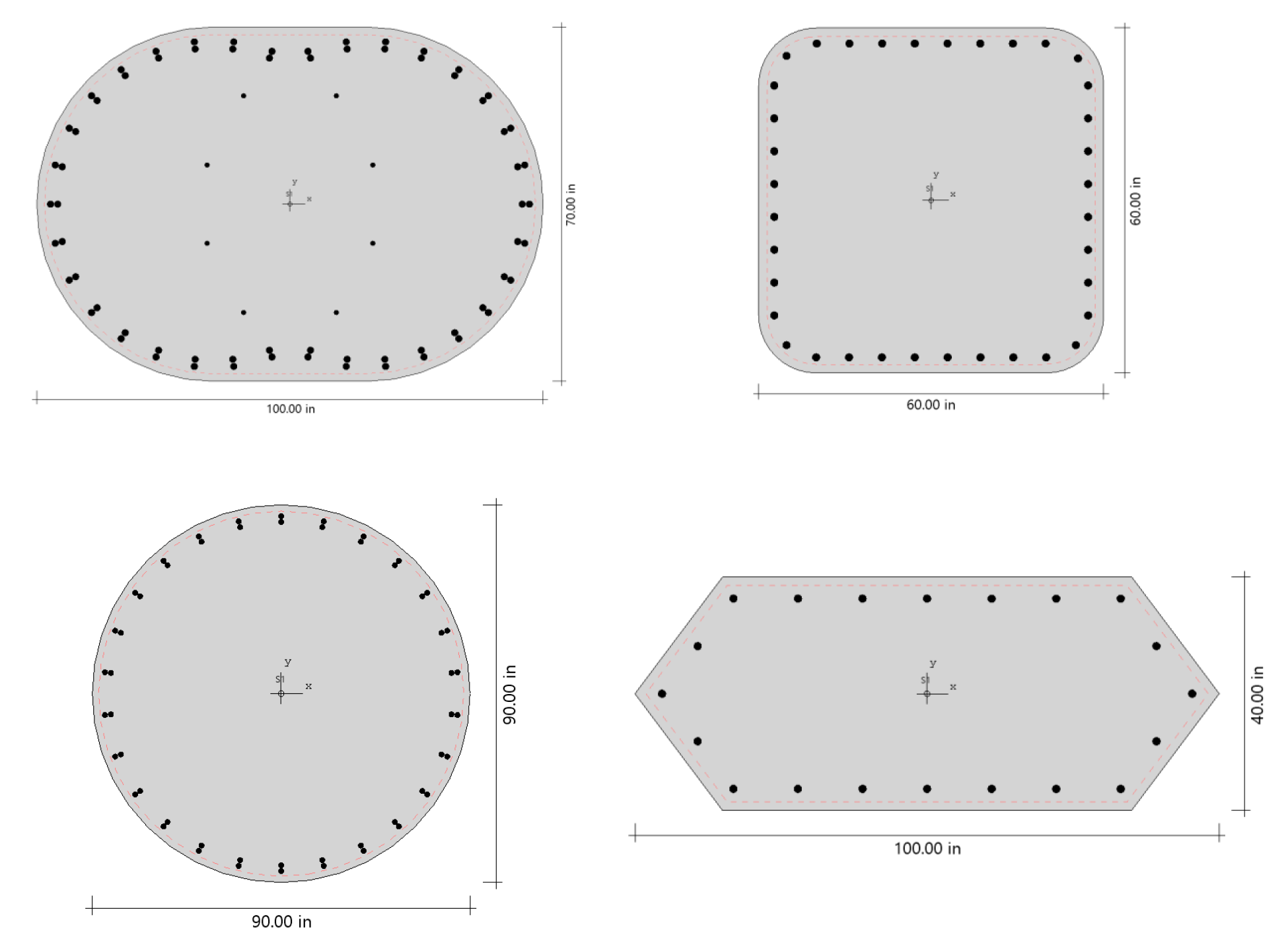
Piers/Pilasters
Sound Walls
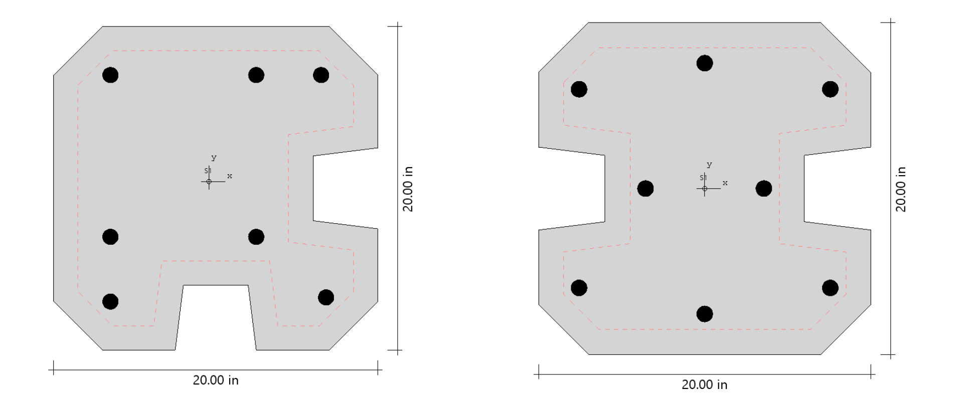
Architectural Columns
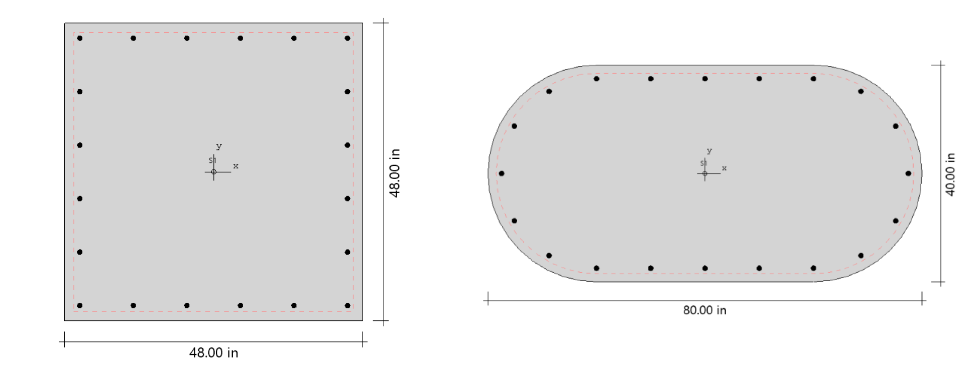
Beams
Global Coordinate System
1. Positive axial forces are compressive and negative axial forces are tensile.
2. Looking in plan at the section with z-axis pointing outwards, the positive x-axis points to the right and the positive y-axis points up. For this section, vectors of positive bending moments have the same orientation as their corresponding axes x and y. Thus, a positive bending moment about the x-axis, Mx, produces tension at the top face of the section and compression at the bottom face. A positive bending moment about the y-axis, My, produces tension at the left face of the section and compression at the right face.
.png)
Figure 2.1 - Positive axial force and bending moments (internal forces)
3. If service loads are input, moment loads at the upper (top) and lower (bottom) ends of the column are needed. Top and bottom moment loads of opposite signs produce single curvature bending. Top and bottom moment loads of the same sign produce double curvature bending.
Positive moment loads at the upper end of the column coincide with positive bending moments. However, at the lower end, positive moment loads produce effects opposite to positive bending moments. Therefore, spColumn changes the sign of the service moment at the lower end to convert it from a moment load to a bending moment.
Axial load is assumed to be constant so it is input only as for the upper end where positive axial load coincides with positive axial force.
4. If factored loads are input, they are considered to be applied at a section pointing upwards so that they have the same orientations as positive axial force and positive bending moments.
.png)
Figure 2.2 - Positive moment loads (external forces)
5. The convention for the slenderness input of beam and column dimensions and their orientation is presented in Figure 2.3 - Slenderness Input Convention. Beams above the columns are shown. Same convention applies to beam below the column.
Figure 2.3 - Slenderness Input Convention
There is no local coordinate system requirement in spColumn