2.3Local Coordinate System
Member definitions, assignments, and results (such as orientation, moments of inertia, deflections, forces, moments, etc.) are defined based on the local coordinate system. spFrame uses the right-hand rule convention to define the local coordinate system. A member location is defined by a start joint and an end joint (a start joint is sometimes referred to as J1 or i-end, and an end joint is sometimes referred to as J2 or j-end). The member positive local x axis points from its start joint towards its end joint and the local y and z axes are defined using the right-hand rule.
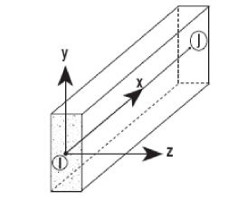
Figure 2.2 Local Coordinate System
For example, for a horizontal member (positive local x-axis is parallel to the positive global x-axis) in space, the positive local y and z axes are parallel to the positive global Y and Z axes, respectively.
For moments or rotations, the right-hand rule explained in Global Coordinate System applies.
The position of a straight prismatic member in space is therefore defined by the global coordinates of the joints at each end, and its orientation in space is defined by the orientation angle, β. For a horizontal member in space (a member whose positive local x axis is parallel to the positive global X-axis), the positive local y axis is defined as the vertical axis perpendicular to the local x axis pointing up. The local z axis is the axis perpendicular to the local xy plane. The orientation angle is the clockwise angle, measured in degrees, between the default local y-axis that spFrame assumes and the member minor axis, yo.
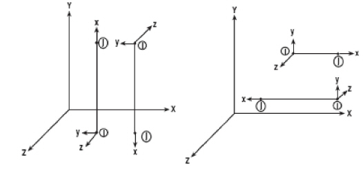
Figure 2.3 Member Orientation Angle
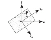
Figure 2.4 Member Orientation Angle