3.61Superimpose Loads on Graphical Image
Show/Load Diagrams command enables you to superimpose defined member and joint applied loads on the model. The scale used to display the loads is set to a predetermined value. This may cause the loads to be shown too small or too large with respect to the model. In such a case you should adjust the scale to suit your viewing needs.
•From the Show menu, select Load Diagrams. The dialog box of Figure 3-49 appears.
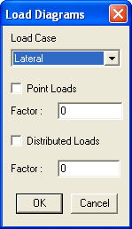
Figure 3-49 Load Diagrams dialog box
•From the LOAD CASE drop-down list box, select the load case whose loads are to be displayed.
•Select the type of load you want displayed, point loads or uniform loads by selecting the corresponding check-box option.
•For each option selected, input a factor to be used in scaling the displayed loads. Input the factor in the FACTOR text box.
•Choose the OK button.
Point and uniform loads are displayed in different colors. Load colors can be changed from the Options/Color command.