5.5Lateral Loads
spCad computes the equivalent static lateral loads (wind or seismic) on a building structure based on the 1991 version of the Uniform Building Code (UBC) and 1990 version of the National Building Code of Canada (NBC). NBC is available if the Metric system of units is selected, and UBC is available with the English system of units.
•The program assumes that the modeled structure is a building structure and the XZ planes are the floor levels.
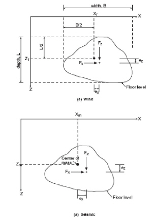
•Each floor width, depth, and weight are computed based on the input geometry and assigned properties. The floor width is the projected dimension along the X axis while the depth is the projected dimension along the Z axis (see Figure 5-11). Floor weight is the weight of all members contained in the plane of the floor level plus the weights of the columns tributary to the floor level. Any panel loads assigned under the SELF load case will also be included in the floor weight.
•Floor dimensions may be increased to account for column dimensions, slab overhang, or exterior wall. Similarly, floor weight to be considered may be increased. Floor dimensions and weight may not be less than the computed values.
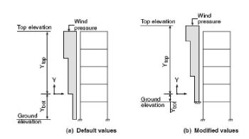
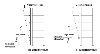
•Ybot, is the distance from the origin to the Ground elevation. The Ground elevation is the elevation below which no lateral loads will be applied to the floors. By default, Ground elevation is taken as the elevation of the lowest plane (see Figure 5-12 and Figure 5-13).
•The elevation of the top floor is taken as the Top Elevation by default. Top elevation may be increased to account for roof parapets. In this case, wind pressure will be applied over the area of the additional elevation, and the additional force will be added to the top level (see Figure 5-12).
•Wind pressure is applied to the face of the structure and is converted to concentrated lateral loads applied to each floor level based on the floor width (or depth, depending on the direction) and tributary height. Variation of wind pressure between floors is taken into account. The concentrated lateral load is applied at the center of the projected width or depth. An eccentricity with respect to the original line of action of the load can be specified (Figure 5-11a).

Figure 5-11 Floor dimensions and lateral load point of application
•The total base shear due to seismic loads is distributed to the floor levels per the selected code. The floor seismic load is applied at the floor center of mass. An eccentricity with respect to the center of mass may be specified (Figure 5-11b).
•When the lateral forces (wind or seismic) are applied to the floors, each floor force is distributed to the floor joints. The force distribution takes into account any load eccentricities. The distribution of the floor force to the joints assumes that the modeled structure is a building structure and that the floor has a rigid diaphragm that distributes the force from the point of application to the joints. Only the joint loads are saved with the data file.

Figure 5-12 Ground and Top elevations for wind loads

Figure 5-13 Ground elevation for seismic loads