5.2Plane Editor
Any frame or truss structure may be divided into a group of two-dimensional planes in the global coordinate system. Figure 5-1 Coordinate Systems shows the three planes of the Plane editor and their orientation. These planes may be parallel to the XY (elevations), YZ (elevations), or XZ (floors) planes of the global coordinate system.
Working in one plane at a time, in-plane joints and members are drawn directly on the screen by simple mouse button clicks. Joints and members may also be moved or deleted.
•A plane is defined by its coordinate, i.e., orthogonal distance from the origin.
•A plane must have a unique label. Default plane labels are based on the plane coordinate.
•For a plane to exist and be valid, it must contain at least one joint.
•As joints and members are drawn or generated,
•spCad creates all possible XY, XZ, and YZ planes that contain them.
•Deleting a plane deletes all joints in that plane along with all connected members.
•A plane’s coordinate may be changed to any value as long as it stays between the coordinates of the two planes immediately before and after it.
•A joint is drawn by clicking on its location on the screen.
•No two joints may have the same coordinates.
•Deleting a joint deletes all members connected to it.
•Moving a joint moves all members connected to it.
•Joints are labeled with numbers based on their order of input.
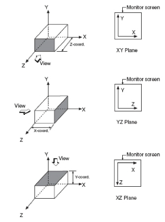
Figure 5-2 Three planes of the plane editor
•A member has a joint at each of its ends.
•To draw a member, click on the first location, move to the second location, and click again. If there is no joint where you click, one will be created.
•No two members may have the same Start and End joints.
•Deleting a member does not delete its end joints.
•Moving a member does not move its end joints but rather creates two new joints.
•Adding a joint along a member divides the member into two.
•Members are labeled with numbers based on their order of input.
•The end of a member closest to the joint with the lowest coordinates in the entire model is designated as its Start Joint (or i-end). Consequently, the other end is the member End Joint (or j-end).
5.2.4Joint and Member Generation
In a plane (level or elevation), a pattern or a layout of joints and members may be repeated more than once. If you draw the typical layout, you can generate the others using Plane’s Copy or Extrude command. Copy is basically a limited version of Extrude and it allows in-plane generation only. Extrude allows in-plane and out-of plane generation.
5.2.4.1(a) Selecting items to be generated
You must select the joints and members to be copied. Joints at selected member ends are automatically selected and may not be excluded from the selection. Selected joints and members will be referred to hereafter as selected items.
After making a selection, a base joint must be picked. This joint must be a selected joint. The generation distance is measured between base joints of successive copies and rotation is done about an axis at the base joint.
5.2.4.3(c) Generation distance
The distance between the selected items and the first generated copy (and consequently, between any two consecutive generated copies) may be specified in rectangular or polar coordinates. Generation distance is measured between a base joint and the next generated base joint.
•For Rectangular coordinates, input the components of the distance (see Figure 5-3a and Figure 5-4a). Vertical and horizontal components are needed for the Copy command. X, Y, and Z components are needed for the Extrude command.
•For Polar coordinates, enter the radius and the angle that define the generation distance (see Figure 5-3b and Figure 5-4b). For the Copy command, the angle is always measured from the horizontal axis. For the Extrude command, two angles are needed, one from the X axis and the other from the Y axis.
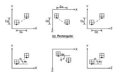
Figure 5-3 Generation distance for the Copy command
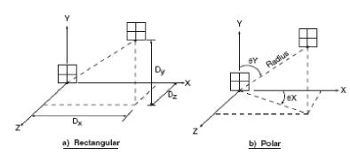
Figure 5-4 Generation distance for the Extrude command
Generated copies may be rotated about the axis orthogonal to the plane when using the Copy command. For the Extrude command, rotation may be specified about any of the three global axes. The right hand rule is used to determine the direction of the rotation (see Figure 5-5).
An increment may be added to the generation distance to increase or decrease the distance between the successive generated items (see Figure 5-6). For example, four copies at a distance of 10 ft and an increment of 5 ft will generate copies at 10, 15, 20, and 25 ft from each other, or at 10, 25, 45, and 70 ft from the original base joint.
Similarly, an increment may be specified with the rotation angle with one difference, the rotation angle of all generated copies is always measured about the original base joint.
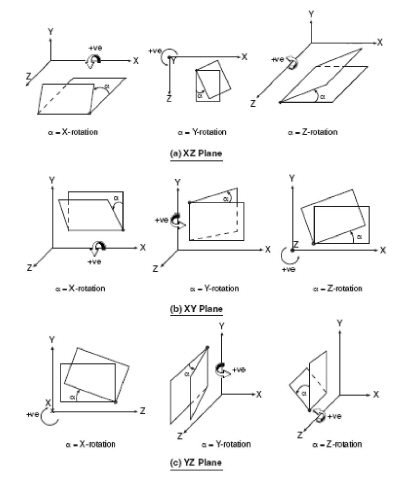
Figure 5-5 Generation angle of rotation
For example, four copies with a rotation angle of 35° and an increment of 5° will generate copies at 35°, 40°, 45°, and 50°, all measured relative to the original position.
This is the number of copies to be generated from the selected items.
5.2.4.7(g) Connecting generated joints
When this option is selected, it instructs the program to create a member connecting any two corresponding joints of every successive copy (see Figure 5-7). A good example of when to use this option is while generating floor levels in a building structure. With this option ON, the columns between the levels are automatically created.
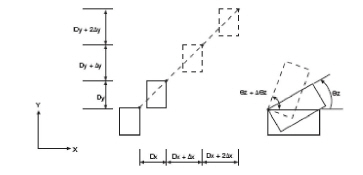
Figure 5-6 Distance and rotation increment
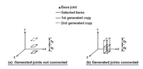
Figure 5-7 Connecting generated joints
Another way of performing in-plane generation is by mirroring selected items. The mirror copy may be about a vertical (see Figure 5-8) or a horizontal (see Figure 5-9) reference line. Mirror copy is performed in-plane only.
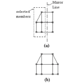
Figure 5-8 Mirroring about a vertical line - (a) before, (b) after
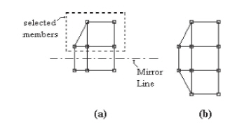
Figure 5-9 Mirroring about a horizontal line - (a) before, (b) after