Unlike spMats v8.xx and earlier versions where the physical model contains the finite element mesh through the creation of grids at the first step of model creation, spMats v10.50 separates the physical model generation from the analytical model. It allows the user define parameters for the Finite Element mesh generation at the Solve Menu. The parameters that can be set by the user are discussed below:
6.2.1. Maximum Allowed Mesh Size
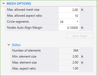
The MAX. ALLOWED MESH SIZE Analytical Model Option is a user input that is set to an initial default value of 2.00 ft by the Program and can be changed by the user based on the specific model needs. As a rule of thumb, as the mesh size gets finer, the results become more accurate. The slab vertices, column, pile, node, restraint, and point load locations automatically get a finite element mesh grid. The factors that may be considered in max. allowed mesh size selection are the slab thickness, and the overall plan dimensions of the slab.
6.2.2. Maximum Allowed Aspect Ratio
The MAX. ALLOWED ASPECT RATIO Analytical Model Option is a user input that is set to an initial default value of 10 by the Program and can be changed by the user based on the specific model needs. As a rule of thumb, as the aspect ratio gets closer to 1, the results become more accurate.
The CIRCLE SEGMENTS Analytical Model Option is a user input that is set to an initial default value of 36 by the Program and can be changed by the user to 8, 12, 24 or 48 based on specific model needs. This option is utilized for circular slabs.
The AUTO ALIGNMENT feature allows users to improve mesh quality by eliminating slender elements that exceed the defined maximum aspect ratio.
After the mesh is generated, some elements may appear distorted or elongated due to minor misalignments between adjacent nodes - especially in regions where nodes are intended to lie on a straight line. Such elements, highlighted in red, typically indicate an aspect ratio higher than the allowable threshold (MAX. ASPECT RATIO).
To address this, the user can specify a tolerance value for the NODES AUTO ALIGN MARGIN and activate the AUTO ALIGN command by clicking the AUTO ALIGN button. The program then identifies and aligns all nodes located within this margin to a common vertical or horizontal axis. This correction results in a cleaner mesh configuration and helps eliminate high aspect ratio elements, which can otherwise compromise the accuracy and stability of the analysis.
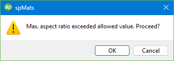
This section lists the number of elements, minimum and maximum element sizes in the model along with the maximum aspect ratio. If the maximum aspect ratio of an element in the model is greater than the defined maximum allowed aspect ratio then the maximum aspect ratio value is highlighted along with all the elements in the mesh whose aspect ratios exceed the maximum allowed aspect ratio. The user is warned before the program invokes the solver.