2
spMats uses the Finite Element Method for the structural modeling and analysis of reinforced concrete slab systems or mat foundations subject to static loading conditions.
The slab is idealized as a mesh of rectangular elements interconnected at the corner nodes. The same mesh applies to the underlying soil with the soil stiffness concentrated at the nodes. Slabs of irregular geometry will be idealized to conform to geometry with rectangular boundaries. Even though slab and soil properties can vary between elements, they are assumed uniform within each element.
The three degrees of freedom are considered at each node are the vertical translation and two rotations about the two orthogonal axes. An external load can exist in the direction of each of the above degrees of freedom, i.e., a vertical force and two moments about the Cartesian axes.
2.1.1Foundation Slab Mat Systems
spMats can be used to model, analyze, and design foundation systems such as mat foundations, spread and combined footings, soil-supported foundations, slabs on grade, pile-supported foundations. Samples of such systems are illustrated below:
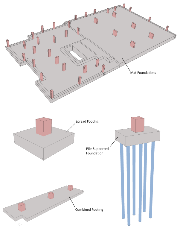
Figure 2-1 Foundation Systems
Global Coordinate System
The mid-surface of the slab lies in the XY plane of the right-handed XYZ orthogonal coordinate system shown in Figure 2-2. The slab thickness is measured in the direction of the Z-axis. Looking at the display monitor, the origin of the global coordinate system is located in the bottom left corner of the screen. The positive X-axis points to the right, the positive Y-axis points upward towards the top of the monitor, and the positive Z-axis points out of the screen. Thus, the XY plane is defined as being the plane of the display monitor.
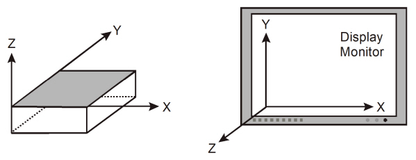
Figure 2-2 Global Coordinate System
Local Coordinate System
There is no local coordinate system requirement in spMats.
2.2Codes and Standards Provisions
Geometry Considerations
The Program does not have any code checks regarding geometry considerations.
Material Considerations
The Program does not have any code checks regarding material considerations.
Loading Considerations
External loads are applied as concentrated nodal loads and/or surface loads according to the sign convention shown in Figure 2-3.
A concentrated nodal load consists of a vertical load, Pz, and two concentrated moments about the X and Y axes, Mx and My. It should be noted that a positive vertical load is applied upward (in the positive Z-direction).
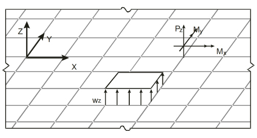
Figure 2-3 Applied Loads
The uniform element surface load, wz, applied over an element is internally discretized by the program into equivalent nodal loads as shown in Eq. 2-1:
Eq. 2-1 
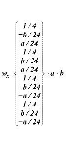
where a and b are the element dimensions.
The self-weight of the slab is computed internally based on the assigned concrete unit weight and the thickness of each element. The self-weight is treated like a surface load and may optionally be considered in the analysis under the dead load case.
Analysis Options
The Program utilizes the Finite Element Method as a method of analysis as permitted in ACI 318-14, 6.2.3 (e). The analysis solver provides the user with options to control foundation model behavior and impose physical restrictions to limit parameters such as maximum displacements and minimum contact area.
Design Options
The Program utilizes the Finite Element Method results to determine the required slab flexural reinforcement in accordance with American (ACI 318) and Canadian (CSA A23.3) design codes. In addition to minimum reinforcement percentage and bar location, spMats provides options to design to either the maximum moment or the average moment within an element. The user can stipulate a number of criteria for generating the finite element mesh before analyzing the model. Options include choices of mesh density and aspect ratio are particularly useful for non-rectangular foundation slabs.
Detailing Options
The Program provides capability for setting the base reinforcement ratio within Design Parameters Tab under Definitions | Properties Section.
The user can utilize reinforcement density contours to detail rebar size and spacing to provide the required strength as required by the selected design code.
Input Phase
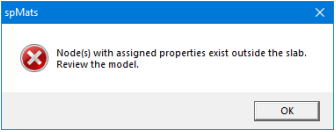
The Program ensures that nodes with assigned properties exist within the slab. If a node with properties such as columns, piles, restraints or loads is assigned outside the slab, the following Error message is displayed.
Output Phase
There are no geometric checks performed by the Program during output phase. However, any warning pertaining to model stability, contact area or exceedance of limits is reported. Detailed information on the solution can be found in the Solver Messages Dialog under Tables Window.
2.3.1Overview of Finite Element Method (FEM) of Analysis
The finite element method is used in spMats for analysis of foundation slabs. During analysis, spMats converts the object-based model into a finite element model. The user defines the mesh used in the analysis by inputting maximum allowed mesh size and maximum allowed aspect ratio. Additional meshing is automatically introduced at slab boundaries, columns, piles, and nodes with assigned properties such as restraints, and point loads.
Definitions and Assumptions
The rectangular plate finite element1 used in spMats has four nodes at the corners and three degrees of freedom (Dz, Rx and Ry) per node, as shown in Figure 2-4. This element considers the thin plate theory, which makes use of the following Kirchhoff hypotheses:
1.Plane sections initially normal to the mid-surface remain plane and normal to that surface after bending.
2.The stress component normal to the mid-plane is small compared to other stress components and is neglected.
3.The deflection of the mid-surface is small compared to the thickness of the plate.
4.The mid-plane remains unstrained subsequent to bending.
The element material is homogeneous, isotropic, and obeys Hooke’s law. Constant thickness and constant material properties are assumed within an element. Cracking effects or changes in the slab elevation are not taken into account in the model.
Note that when deflections are not small, the bending of plates is accompanied by strain in the mid-plane. Further, for thick slabs, shear deformations (which are not considered by the program) may be significant, and a finite plate element based on the more general Mindlin’s Theory may be required.
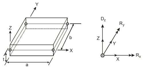
Figure 2-4 Plate Finite Element
The model can be supported by soil assigned to a slab and/or by piles, nodal restraints, nodal springs, and slaved degrees of freedom that can assigned to nodes. Each support option is discussed below.
Soil Support - Winkler’s Foundation
The soil supporting the slab is modeled as a group of linear uncoupled springs (Winkler type) concentrated at the nodes. The soil element is tensionless, weightless, and has one degree of freedom, which is the displacement in the Z direction (Dz). The contribution of each element node to the soil spring stiffness is equal to the nodal tributary area (1/4 the element area) multiplied by the soil subgrade modulus, Ks, under the element. The common nodes of adjacent elements undergo the same displacement. Therefore, if the adjacent elements have dissimilar soil properties, the soil pressures at the common nodes of these elements will differ in proportion to their respective soil subgrade modulus values.
The contact pressure, Pz, under each element node is proportional to the nodal displacement, Dz.
Eq. 2-2 
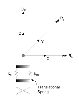
Figure 2-5 Soil and Nodal Springs
Usually, several factors are considered in the determination of the subgrade modulus: the size and shape of the footing, soil type below the footing and deeper, type and duration of loading, footing stiffness, and superstructure stiffness. The program does not perform any correction on the input subgrade modulus to account for these or any other factors.
Additional nodal springs may be applied in parallel to the Winkler’s springs, as shown in Figure 2-5. Accordingly, their linear stiffness, Kns, is added to the equivalent spring constant.
The nodal spring reaction at a particular node is proportional to the nodal displacement, Dz
Eq. 2-3 
Piles
Piles are modeled as springs connected to the nodes of the finite element model.
The spring constant, Kp, for a pile is calculated from the formula:
Eq. 2-4 
where Qu denotes the load applied to the pile and S is the corresponding settlement of the pile. Assuming soil allowable pressure, Pall, acting on the pile base, Qu equals Pall =Ap, where Ap is pile cross sectional area. Neglecting long-term effects, the settlement of pile is estimated from the empirical formula for a single pile in cohesionless soil2:
Eq. 2-5 
where D is pile diameter, L is pile length, and Ep is modulus of elasticity of pile material. The above formula is units independent as long as all of its terms have consistent units. For noncircular piles, an effective diameter is calculated from the formula:
Eq. 2-6 
Nodal Restraints
All nodal degrees of freedom (DOF) are assumed to be initially released (i.e., free to move). Mathematically speaking, each DOF implies an equilibrium equation; however, nodal DOFs may be fully restrained against displacement and/or rotation.
Nodal Springs
Partial restraint in the Z direction is possible with the use of translational springs.
Slaved Degrees of Freedom
Slaved degrees of freedom may be assigned to a group of nodes to share the same displacement or rotation. Slaving enforces uniform deformation modes at selected nodes that can help in modeling stiff structural elements such as walls and pedestals. Applying a full restraint and slaving of a node (or nodes in a group) for the same degree of freedom is not allowed. Either only restraining all nodes (zero displacement) in a group or only slaving of all nodes in a group (same non-zero displacement) should be applied.
Slaving of degrees of freedom produces a stiffer slab system and reduces the number of equations to be solved. It should be noted that slaved degrees of freedom (SLDOF) are assigned by grouping of nodes. A group of nodes can be designated to share the same Dz, Rx, or Ry. If a group of nodes should share all three degrees of freedom, three different SLDOF groups (one for each DOF) must be defined. It should also be noted that a node can belong to more than one SLDOF group as long as these groups are slaved for different degrees of freedom. The external load corresponding to a SLDOF group corresponds to the sum of loads applied to all slaved nodes in the groups.
2.3.3Determination of Internal Forces
The Program determines the element internal moments as shown below:
Element Internal Moments
The bending moments, Mxx and Myy, and the twisting moment, Mxy, are computed at the corner nodes of each element. Figure 2-6 shows the element moment sign convention used by the program. Note that unlike in beams and columns, the traditional plate and shell theory convention is that Mxx denotes the moment along (not about) the X-axis and Myy denotes the moment along the Y-axis. Both moments are positive when they produce tension at the top.
The principal moments, Mr1 and Mr2, and the principal angle (see Figure 2-7), are computed from the general moment transformation equations:
Eq. 2-7 
Eq. 2-8 
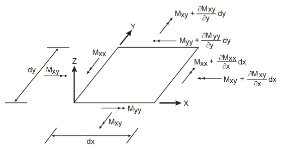
Figure 2-6 Element Nodal Moments
Note that since Mr1 and Mr2 are principal moments, the twisting moment associated with the r1-r2
axes (Mr12) is zero:
Eq. 2-9 
and the angle θ is:
Eq. 2-10 
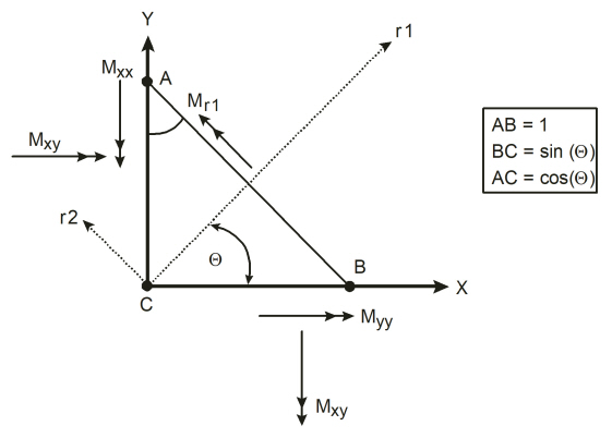
Figure 2-7 Element Principal Moment
2.3.4Displacements and Pressures
Displacements
The Program calculates the displacements, namely displacement, Dz, X-Rotation, Rx, and Y-Rotation, Ry, at all four nodes of an element for both service load and ultimate load combinations. Service-level nodal vertical displacement, Dz, envelopes are also reported by the Program.
During analysis, if a node undergoes upward vertical displacement, the Program disconnects that node from the analysis model and iterates the solution. The maximum allowed service vertical downward displacement value can be set by the user under Solve Option and its default value is 11 in.
Under Solve Options when “Uplift occurs when displacement exceeds” user-input is entered as positive value; the Program permits an upward vertical displacement of a node up to that value without disconnecting the node. However, this user-input must be set to zero if a particular model contains a soil-supported node. An ideal use of this option is for foundations supported by piles where piles have tensile capacity. The soil, however stiffness it has, under the foundation must be ignored in modeling in such a model for accuracy of calculations.
Pressures
The Program calculates the soil pressures at all four nodes of an element for both service load and ultimate load combinations. The calculated soil pressures are compared with the allowable pressure values during the analysis. If the calculated soil pressure exceeds the allowable pressure specified by the user, the Program displays a warning message when analysis is completed and elements with this conditions are indicated in the graphical pressure contours view.
The Program utilizes the FEM analysis results in order to calculate the flexural reinforcement according to American (ACI 318) and Canadian (CSA A23.3) design codes. For each element in the analysis model, spMats processes the results to determine applicable design moments are consequently used to calculate the required flexural reinforcement per the selected code edition.
Element Design Moments
The Principal of Minimum Resistance3 is used by the program to obtain values for the design moments, which include the effects of the twisting moment.
The equivalent design bending moments, Mux and Muy, for the design of reinforcing steel respectively in the X and Y direction are computed as follows:
•For top reinforcement where positive moments produce tension:
Eq. 2-11 
Eq. 2-12 
However, if either Mux or Muy is found to be negative, the negative value of the moment is changed to zero and the other moment is given as follows:
Eq. 2-13 if Mux < 0, then Mux = 0 and 
Eq. 2-14 if Muy < 0, then Muy = 0 and 
•For bottom reinforcement where negative moments produce tension:
Eq. 2-15 
Eq. 2-16 
However, if either Mux or Muy is found to be positive, the positive value of the moment is changed to zero and the other moment is given as follows:
Eq. 2-17 if Mux > 0, then Mux = 0 and 
Eq. 2-18 if Muy > 0, then Muy = 0, and 
Flexural Reinforcement
The Program reports the area of flexural reinforcement per unit width [in2/ft (US Customary Units) or mm2/m (Metric Units)]. The total area of reinforcement in an element, then, can be obtained by multiplying the reported area of reinforcement by the width of the element.
Asx reinforcement is placed along X-direction and calculated based on the greater of the design moment, Mux or the minimum reinforcement ratio specified by the user under Design Parameters Input Menu.
Similarly, Asy reinforcement is placed along Y-direction and calculated based on the greater of the design moment, Muy or the minimum reinforcement ratio specified by the user under Design Parameters Input Menu.
For computation of the required flexural reinforcement, the Program offers two options under Solve Options. These are:
•Compute required reinforcement based on maximum moment within an element.
•Compute required reinforcement based on average moment within an element.
The assumptions in determination of required flexural reinforcement are based on the design moment conform to the design specifications based on the accepted Strength Design Method and Unified Design Provisions. These are:
1.The reinforcement is computed based on a rectangular section with no compression reinforcement and one layer of tension reinforcement.
2.The maximum usable strain at the extreme concrete compression fiber is 0.003 for ACI standards and 0.0035 for CSA standards.
3.The rectangular concrete stress block is assumed with the block depth equal to:
Eq. 2-19 a = β1c
where c is the distance from the extreme compression fiber to the neutral axis and factor β1 equals
Eq. 2-20 
for ACI standards and
Eq. 2-21 
for CSA standards
4.To compute the stress in the steel layer, the elastic-perfectly plastic stress strain distribution is used. The required area of reinforcing steel is calculated as:
Eq. 2-22 
which reinforcement ratio, ρ, equal to
Eq. 2-23 
where factors m and g are calculated for ACI standards as
Eq. 2-24 
Eq. 2-25 
with strength reduction factor φ = 0.9 for tension-controlled sections4. For CSA standards, factors m and g are equal to
Eq. 2-26 
Eq. 2-27 
where α1 is defined as
Eq. 2-28 
and steel resistance factor5 ϕs = 0.85 and concrete resistance factor6, ϕc, that takes value of ϕc = 0.60 for CSA A23.3-94, ϕc = 0.65 for CSA A23.3-04 and CSA A23.3-14, and ϕc = 0.70 in case of precast concrete for CSA A23.3-04 and CSA A23.3-14 standards.
α1 is the ratio of the average stress in the rectangular compression block to the specified concrete strength. It equals 0.85 for ACI Code7 and 0.85 − 0.0015fc’ but not less than 0.67 for the CSA Standard8.
Maximum Reinforcement
For the ACI Code, the maximum reinforcement ratio is derived from the condition9 that the net tensile strain at nominal strength is not less than 0.004.
For the CSA Standard, the area of tension reinforcement is such that the neutral axis-to-depth ratio is:
Eq. 2-29 
When the required area of steel exceeds the maximum allowed by the code, the program provides a warning message during solution stating that steel design of some elements failed.
Minimum Reinforcement
The Program does not automatically check the minimum reinforcement requirement per design code. Instead, the Program allows the user to input minimum reinforcement ratio % per layer under Design Parameters Menu.
The minimum amount of reinforcement in each layer is computed as the minimum reinforcement ratio % defined by the user multiplied by the gross area. Since minimum reinforcement area is calculated by the program separately for each of the two layers, the user should provide half of the minimum reinforcement ratio stipulated by design standards for total reinforcement in order to meet the standards requirements.
For ACI, the minimum total reinforcement amount required in foundations is equal to10 0.002Ag for steel Grade 40 or 50, 0.0018Ag for steel Grade 60, and (0.0018·60,000/fy)Ag for reinforcement with yield stress exceeding 60,000 psi.
For CSA standards11, the minimum reinforcement requirement is equal to 0.002Ag.
The Minimum Reinforcement Ratio percentage (%) input under Define | Design Parameters Menu can be utilized by the user for base reinforcement selection. Once the reinforcement selection is expressed with this input, the Program shall select that amount as a minimum reinforcement in the output.
For example, for 24” thick mat foundation, the user intends to place #5 @ 12” reinforcement Top & Bottom. Note that “Min Reinf. Ratio % input is per layer. With the given data, this input shall be (0.31) * 100 / (12 * 24) = 0.1076 % which will be equal to 0.31 in2 / ft reinforcement per layer as shown below.
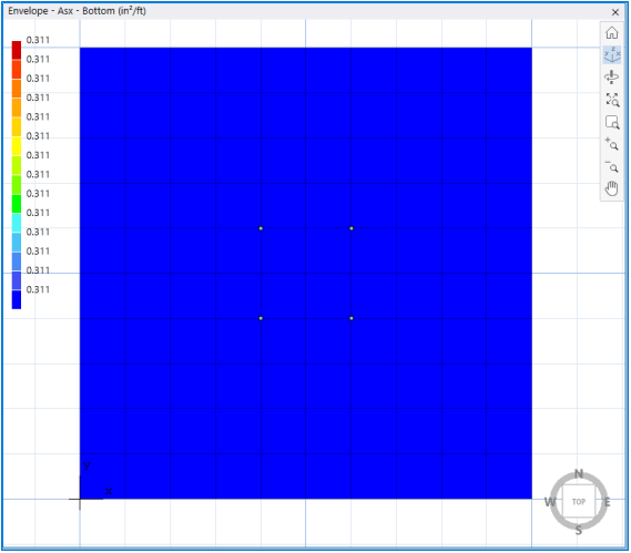
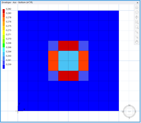
If by analysis, the minimum base reinforcement is insufficient in some parts of the model, this condition shall be displayed as shown below.
2.6.1Single Layer of Reinforcement Modeling
In order to simulate single layer reinforcing, top and bottom reinforcement covers may be inputted such that they are at the same plane per direction. It is important to note that the Min. Reinf. Ratio (% of Ag per layer) is to be kept equal to the design code minimum (i.e. 0.18%) since the governing reinforcement per element will then be selected manually as the maximum of the top and bottom reinforcement per direction. i.e. For X-direction, MAX[Asx Top, Asx Bottom], Y-direction, MAX[Asy Top, Asy Bottom].
The designer may consider entering different cover values for X and Y direction reinforcement to simulate actual rebar placement.
Refer to the Technical Article for additional details: Industrial Floor Slab on Grade with Single Layer of Reinforcement
2.6.2Fiber Reinforced Slabs on Grade Modeling
Ground supported slabs in industrial and residential floors may be specified with fiber reinforcement in lieu of a single layer of reinforcing or welded wire fabric. Such slabs are referred to as membrane slabs, floating slabs, or filler slabs and range in thickness from as little as 4" to 8" depending on the supported loads. In warehouses and storage facilities such slabs may be subjected to concentrated point loads from storage rack posts or forklift wheel loads.
Refer to the Technical Article for additional details: Fiber Reinforced Industrial Floor Concrete Slabs on Grade
2.6.3Plain Unreinforced Concrete Slabs on Grade Modeling
Ground supported slabs with light loading and residential flooring are frequently designed without reinforcing (unreinforced). Such plain concrete slabs are referred to as membrane, floating, or filler slabs and range in thickness from as little as 4" to 8" depending on the supported loads. In warehouses and storage facilities such slabs are subjected to concentrated point loads from storage rack posts or forklift wheel loads.
Refer to the Technical Article for additional details: Plain Unreinforced Concrete Slabs on Grade
2.6.4Pile Cap Design Considerations
Thick concrete mat with piles are commonly referred as pile caps and require detailed consideration of pile location and spacing. Two technical articles provide additional guidance for completing pile cap models.
Pile Supported Foundation (Pile Cap) Analysis and Design
Pile Reaction Distribution in Pile Cap Foundations
The punching shear in spMats has been eliminated in version 10.00. A more detailed and comprehensive treatment of punching shear around columns and piles in spMats models is being developed and will be featured in a future release of spMats.
The provisions used for punching shear analysis in spMats v8.50 and prior are provided in this section for reference.
Punching Shear Analysis
The punching shear in spMats is checked where columns in conjunction with concentrated loads and where piles are assigned as supports.
ACI Standard
For ACI standards, the following condition is used:
Eq. 2-30 
where
vu = factored shear stress,
vn = nominal shear resistance of slab,
ϕ = shear resistance factor equal to 0.75.
The nominal shear resistance, vn, is a sum of nominal shear resistance provided by shear reinforcement, vs, and nominal shear resistance, vc, provided by concrete. In spMats, vs is assumed to be zero and vc is taken as the smallest of vc1, vc2, and vc3, which are respectively equal to12:
Eq. 2-31 
Eq. 2-32 
Eq. 2-33 
with:
βc = the ratio of long side to short side of the column (or the pile),
αs = 40 for interior, 30 for edge, and 20 for corner columns or piles,
b0 = perimeter of the critical section,
d = average effective depth of the critical section segments (less pile embedment, if any),
 = square root of compressive strength of concrete,
Eq. 2-34 

CSA Standard
Similarly, for the CSA standards, factored shear stress, vf, is checked against factored shear resistance, vr, which only takes into account concrete shear resistance calculated as the minimum of the following three values:
Eq. 2-35 
Eq. 2-36 
Eq. 2-37 
for the CSA A23.3-94 Standard13, and
Eq. 2-38 
Eq. 2-39 
Eq. 2-40 
for the CSA A23.3-04 and CSA A23.3-14 standards14. Factor αs equals 4 for interior columns, 3 for edge columns, and 2 for corner columns for all CSA standards. Factor λ accounts for low density concrete and is equal to:
Eq. 2-41 

Also, for interior column and piles, the value of effective depth, d, in Eq. 2-38 through 2-40 will be multiplied15 by factor 1300/(1000+d).