2.4. Design Methods
2.4.1. Area of Reinforcement
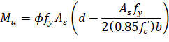
The program calculates the required area of reinforcement (top and bottom) based on the values of bending moment envelope within the clear span. For rectangular sections with no compression reinforcement, the design flexural strength of the column strip, middle strip and beam must equal the factored design moment:
| Eq. 2-80 |
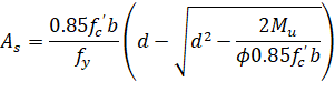
The reinforcement can therefore be computed from:
| Eq. 2-81 |
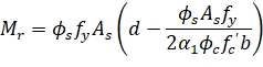
For CSA A23.3:
| Eq. 2-82 |
The effective depth of the section is taken as the overall section depth minus the distance from the extreme tension fiber to the tension reinforcement centroid. The column strip depth may include all or part of the drop panel depth. The drop depth will not be included in the effective depth of the column strip when the drop does not extend at least one-sixth the center-to-center span length in all directions, or when the drop depth below the slab is less than one-quarter the slab depth. If the drop extends at least one-sixth the center-to-center span length and the drop depth is greater than one-quarter the distance from the edge of the drop panel to the face of the column or column capital, the excess depth will not be included in the column strip effective depth. If the drop width is less than the column strip width, the drop width will be used in the computation of the required reinforcement.
When computing negative slab reinforcement and additional reinforcement for negative unbalanced moments over the supports, the contribution of the depth of transverse beam can be optionally selected. The contribution of transverse beam will be considered, if it extends beyond the critical section and if its depth exceeds the depth of the drop panel. The increase of the slab thickness is limited to ¼ of the extent of the transverse beam beyond the face of support, identical to design depth limitations for drop panels. If transverse beam depth exceeds the limit, excess depth is disregarded in the reinforcement calculations.
For two-way slabs with beams, an option exists when designing reinforcement for positive bending moments, to include a portion of slab as beam flanges149 (T-Section). The width of the column strip is then decreased accordingly. The extent of the flanges on each side is limited to four times slab thickness and not more that the projection of the beam under the slab. When this option is not selected, beam geometry is treated as rectangular. When calculating required reinforcement for negative bending moments the geometry of the beam is treated as rectangular, having beam width equal to web width. However, when a T-Section is selected, reinforcing bar design is performed assuming that they are distributed across the beam width including the flanges.
For the ACI 318-99 code the strength reduction factor for flexure calculations is specified as ϕ = 0.90150.
For the ACI 318-14, ACI 318-11, ACI 318-08, ACI 318-05, and ACI 318-02 codes the strength reduction factor for tension-controlled sections (εt ≥ 0.005) is equal ϕ = 0.90. For transition sections (fy / Es ≤ εt ≤ 0.005) the strength reduction factor can be linearly interpolated by the formula151.
| Eq. 2-83 |
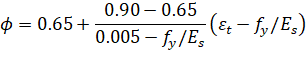
ACI 318-14, ACI 318-11, ACI 318-08, ACI 318-05, and ACI 318-02 codes specify the strength reduction factor for compression controlled sections (εt < fy / Es) as equal ϕ = 0.65. The reduction factors for transition or compression controlled sections have application primarily in investigation mode of the program. In design mode the program performs the calculations assuming a tension controlled section (εt ≥ 0.005) or a section with compressive reinforcement (if enabled).
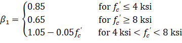
The ACI 318-99 code152 requires keeping the steel ratio below the maximum value, ρmax, equal to 75% of steel ratio producing balanced strain condition, ρb, where153:
| Eq. 2-84 |
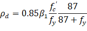
with
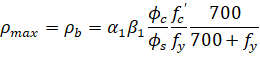
For CSA code the value of ρmax equals ρb and is calculated as follows154:
| Eq. 2-85 |
where: | ||
• | ||
• |
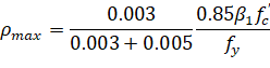
The ACI 318-14, ACI 318-11, ACI 318-08, ACI 318-05, and ACI 318-02 codes control the amount of reinforcement by limiting the value of net tensile strain (εt ≥ 0.004)155.
The program satisfies this condition by assuming a tensioned controlled section with εt ≥ 0.005. From this assumption the equivalent maximum reinforcement ratio for rectangular section can be written as:
| Eq. 2-86 |
If the calculated reinforcement exceeds the maximum allowed, a message will appear in the output. In such cases, it is recommended that the engineer review the slab thickness to ensure a more satisfactory design. If compression reinforcement calculations are enabled, the program will attempt to add compression reinforcement to the section. The program is capable to design compressive reinforcement for any design strip (column, middle, and beam) including also unbalanced moment strip156.
The amount of reinforcement provided will not be less than the code prescribed minimum. For the ACI 318 code, the minimum ratio of reinforcement area to the gross sectional area of the slab strip using Grade 60 reinforcement is taken as 0.0018. When reinforcement yield strength exceeds 60 ksi, the minimum ratio is set to 0.0018 × 60 / fy. For reinforcement with yield strength less than 60 ksi, the minimum ratio is set to 0.0020. In no case will this ratio be less than 0.0014 (See Table 2.5) 157.
The CSA Standard requires a minimum ratio of slab reinforcement area to gross sectional area of the slab strip equal to 0.002 for all grades of reinforcement158.
fy (ksi) | As/Ag |
< 60 | 0.0020 |
≥ 60 |
|
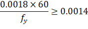
Table 2.5 - Minimum Ratios of Reinforcement to Gross Concrete Area
According to ACI code for beams and positive moment regions of joist slabs, minimum reinforcement provided will not be less than159:
| Eq. 2-87 |
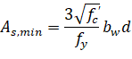
and not less than 200bwd / fy where bw is the web width of the section. For statically determinate sections with flange in tension, bw is replaced by the smaller of 2bw and the width of the flange.
Similar equation prescribed by CSA A23.3 code has the form160:
| Eq. 2-88 |
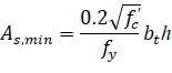
where bt is the width of the tension zone of the section. Additionally, for T-sections having flange in tension the CSA code limits value of bt to 1.5bw for single sided flanges and to 2.5bw for double sided flanges.
When designing reinforcement for longitudinal slab bands according to CSA code, program assumes identical minimum steel requirements as for beams.
2.4.1.1. Design for Combined Flexure, Shear, and Torsion
CSA A23.3-14/04 requires, in proportioning of longitudinal reinforcement, to include additional tension forces caused by shear and torsion161.
To achieve this, the program calculates forces developed in the longitudinal reinforcement due to flexure, shear, and torsion.
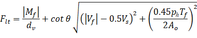
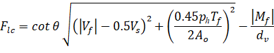
On the flexural tension side the force in longitudinal reinforcement is equal to162.
| Eq. 2-89 |
On the flexural compression side the force in longitudinal reinforcement is equal to163.
| Eq. 2-90 |
but not less than zero.
For these forces, longitudinal reinforcement area is calculated from the following equations164.
| Eq. 2-91 |
| Eq. 2-92 |


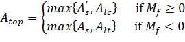
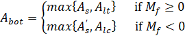
Taking into account both positive and negative bending moments (resulting from all load combinations and load patterns) and checking against area of steel required for flexure only, the final areas of top and bottom reinforcement can be calculated from:
| Eq. 2-93 |
| Eq. 2-94 |
2.4.2. Concentration and Additional Reinforcement
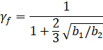
spSlab computes the fraction of the unbalanced moment, γf Mu, that must be transferred by flexure within an effective slab width (a band) equal to the column width plus one and one-half the slab or drop panel depth (1.5h) on either side of the column where165:
| Eq. 2-100 |
The amount of reinforcement required to resist this moment is computed. The amount of reinforcement already provided for flexure is then computed from the bar schedule (i.e. the number of bars that fall within the effective slab width multiplied by the area of each bar). Depending on load conditions, additional negative or positive reinforcement may be required. If the reinforcement area provided for flexure is greater than or equal to the reinforcement requirements to resist moment transfer by flexure, no additional reinforcement is provided, and the number of additional bars will be set to 0. If the amount of reinforcement provided for flexure is less than that required for moment transfer by flexure, additional reinforcement is required. The additional reinforcement is the difference between that required for unbalanced moment transfer by flexure and that provided for design bending moment in the slab, and it is selected based on the bar size already provided at the support.
For ACI codes the value of γf on selected supports can be automatically adjusted to the maximum permitted value. The corresponding value of γv = 1 – γf is adjusted accordingly. This option allows relaxing stress levels for two-way shear around the columns by transferring increased part of the unbalanced moment through flexure. The adjustment is performed independently for each load case and pattern. If for given load case the corresponding two-way shear Vu exceeds the appropriate limits 0.75ϕVc at an edge support, 0.5ϕVc at a corner support, or 0.4ϕVc at an interior support, adjustment of both factors is not performed.
When the adjustment of γf and γv factors is selected, the reinforcement calculated within the transfer width should be limited according to the code to reinforcement ratio ρ < 0.375ρb, as stipulated in ACI 318-99/02/05166, or limitation of net tensile strain εt > 0.010, as required by ACI 318-14, ACI 318-11 and ACI 318-08167.
Violation of this requirement is reported by the software as exceeding maximum allowable reinforcement indicating that the option to adjust the factor γf should be turned off by the user at the support where the violation occurs.
It should be noted that the ACI code168 requires either concentration of reinforcement over the column by closer spacing, or additional reinforcement, to resist the transfer moment within the effective slab width. spSlab satisfies this requirement by providing additional reinforcement without concentrating existing reinforcement.
When computing additional reinforcement for the transfer of negative and positive unbalanced moments over the supports through flexure in systems with longitudinal beams, the contribution of the longitudinal beam cross-section can be optionally selected. If selected, this contribution will be considered. For CSA designs this functionality extends also to design of banded reinforcement in bb strip.
The CSA A23.3 code requires at least one-third of the total negative reinforcement for the entire design strip at interior supports to be concentrated in the band width, bb, extending 1.5hs from the sides of the columns169.
The program fulfills this requirement by concentrating a portion of reinforcement assigned to the design strip that includes width bb. This strip will typically be the column strip. However, if longitudinal slab bands or slab-band-like beams wider than band width bb are present, then reinforcement assigned to these elements is concentrated.
At exterior supports, the total negative reinforcement is placed in the bb band width170 or if a beam narrower than bb is present, then the total reinforcement is placed within the beam width171.
The reinforcement in the bb and the remaining portions of the design strip is also checked for compliance with spacing and minimum reinforcement requirements.