2.5. Detailing Provisions
Proper reinforcement detailing is a critical step in ensuring the performance and safety of structural systems designed using spSlab and spBeam. The detailing process involves selecting the size, spacing, and extension of reinforcement in accordance with the requirements of design codes, such as ACI 318 and CSA A23.3. Adhering to these guidelines ensures that the structural elements achieve the intended capacities while maintaining durability, ductility, and resistance to cracking and progressive collapse.
This section outlines the methodology and criteria employed by spSlab and spBeam to assist users in determining optimal reinforcement layouts. It covers key aspects of reinforcement detailing, spacing limitations, development lengths, and structural integrity reinforcement. The iterative design approach used by the programs incorporates considerations such as bar sizes, clear spacing, and crack control requirements to meet both minimum and maximum limits required by the code.
Additionally, provisions for structural integrity and corner reinforcement are discussed to enhance the redundancy and ductility of the structural system.
2.5.1. Reinforcement Detailing
2.5.1.1. Minimum Clear Spacing
According to ACI-318 code172, the default minimum clear spacing of reinforcement for both slabs and beams is taken as the larger of the two prescribed minima of one bar diameter, db, or 1 in. According to CSA code173, the default minimum clear spacing of reinforcement for both slabs and beams is taken as the larger of the two prescribed minima of 1.4 times the bar diameter, db, or 1.2 in (30 mm). The user may select a clear spacing greater than the default value to take into account tolerances for reinforcement placement174 and other project specific considerations.
For two-way systems, the maximum spacing of reinforcement is kept at two times the slab thickness for the ACI code175 and three times the slab thickness for the CSA code176, but no more than 18 in. or 500 mm respectively. For joist systems the limit is increased to 5 times the slab thickness177. When calculating negative support reinforcement for the CSA code178, the program assumes that banded reinforcement over supports is spaced at a maximum of 1.5hs and no more than 250 mm.
For one-way slabs, the maximum spacing is limited to179 the smaller of three times the slab thickness and 18 in. [500 mm].
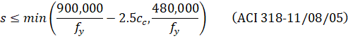
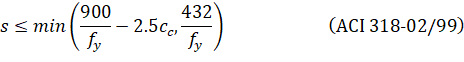
Additionally, the maximum spacing of reinforcement, s, in beams and one-way slabs is selected so that the following crack control requirements of the ACI and the CSA codes180 are met:
| |
| Eq. 2-95 |
|

where: | ||
• cc | = | least distance from the surface of bar to the tension face, |
• dc | = | distance from extreme tension fiber to center of the closest longitudinal bar, |
• A | = | effective tension area of concrete surrounding the flexural tension reinforcement and extending from the extreme tension fiber to the centroid of the flexural tension reinforcement and an equal distance past that centroid, divided by the number of bars or wires, |
• zmax | = | 30,000 N/mm for interior exposure or 25,000 N/mm for exterior exposure, multiplied by a factor of 1.2 for epoxy-coated reinforcement. |
An iterative process is performed to determine the number of bars and bar size. The initial number of bars is determined by dividing the total reinforcement area required, As, by the area of one bar, Asb, of the input minimum bar size. Next, the spacing is determined. If the minimum spacing limitations are violated, the bar size is increased and the iterative process is repeated until all bars sizes have been checked. If the maximum spacing limitations are not met, the number of bars required to satisfy these limitations is computed and the iteration process terminates.
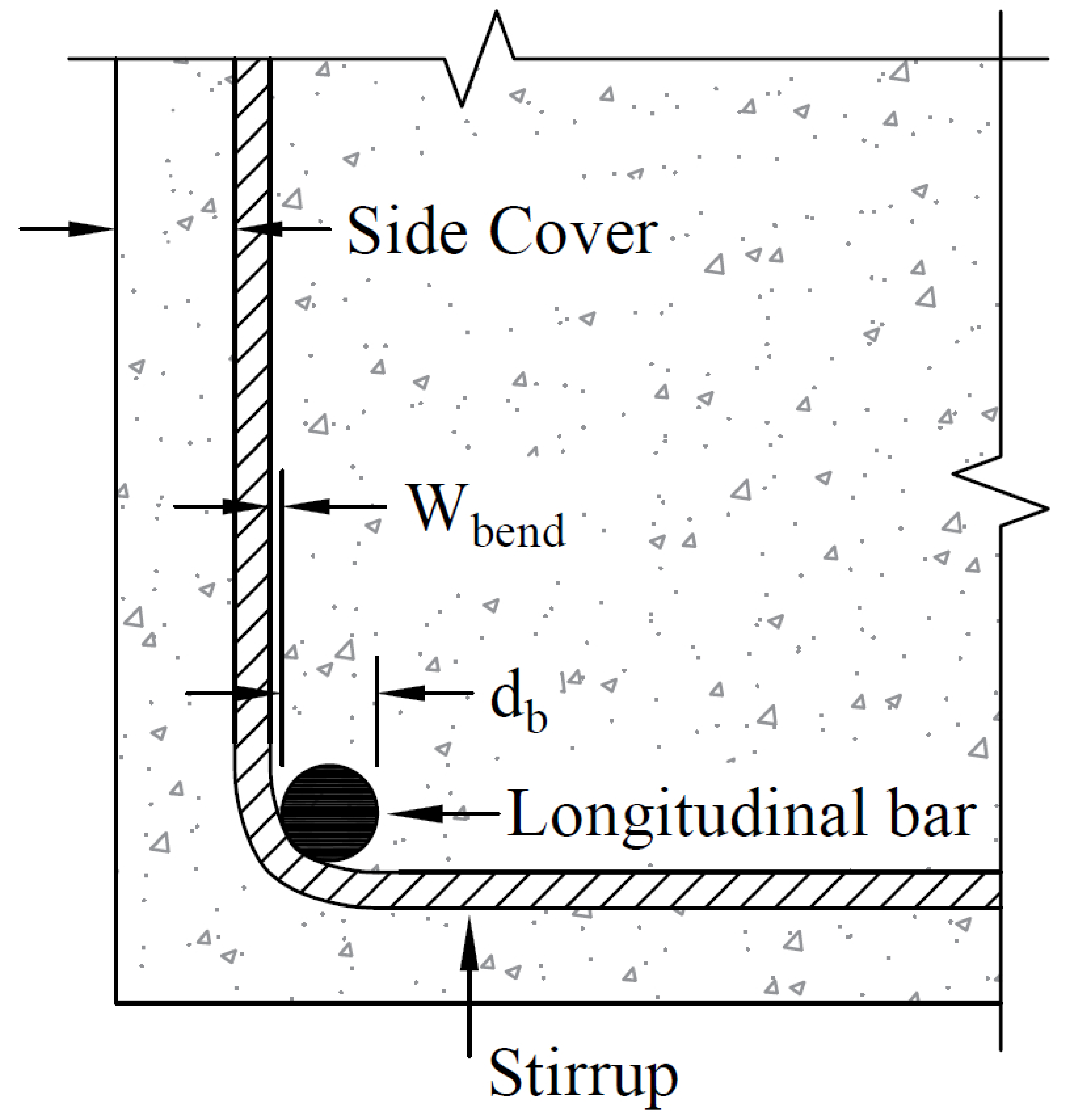
Figure 2.28 - Width due to Stirrup Bend
For beams, layered reinforcement is provided if sufficient beam width is not available. The clear distance between layers is assumed 1.0 in [30 mm] but the user can change this value. By default, the program assumes a 1.5 in [40 mm] side cover to stirrup for width calculations and this value can also be changed by the user.
The program also assumes that the longitudinal bar makes contact at the middle of the stirrup bend where the minimum inside diameter of the bend is four times stirrup diameter181.
Therefore, an additional width is added to the cover for longitudinal bars less than size #14 (#45 for CAN/CSA-G30.18) (Figure 2.28 - Figure 2.29). This additional width due to the, wbend, is equal to:
| Eq. 2-96 |
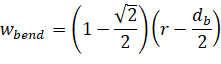
where: | ||
• db | = | diameter of the longitudinal bar, |
• r | = | inside radius of bend for stirrup. |
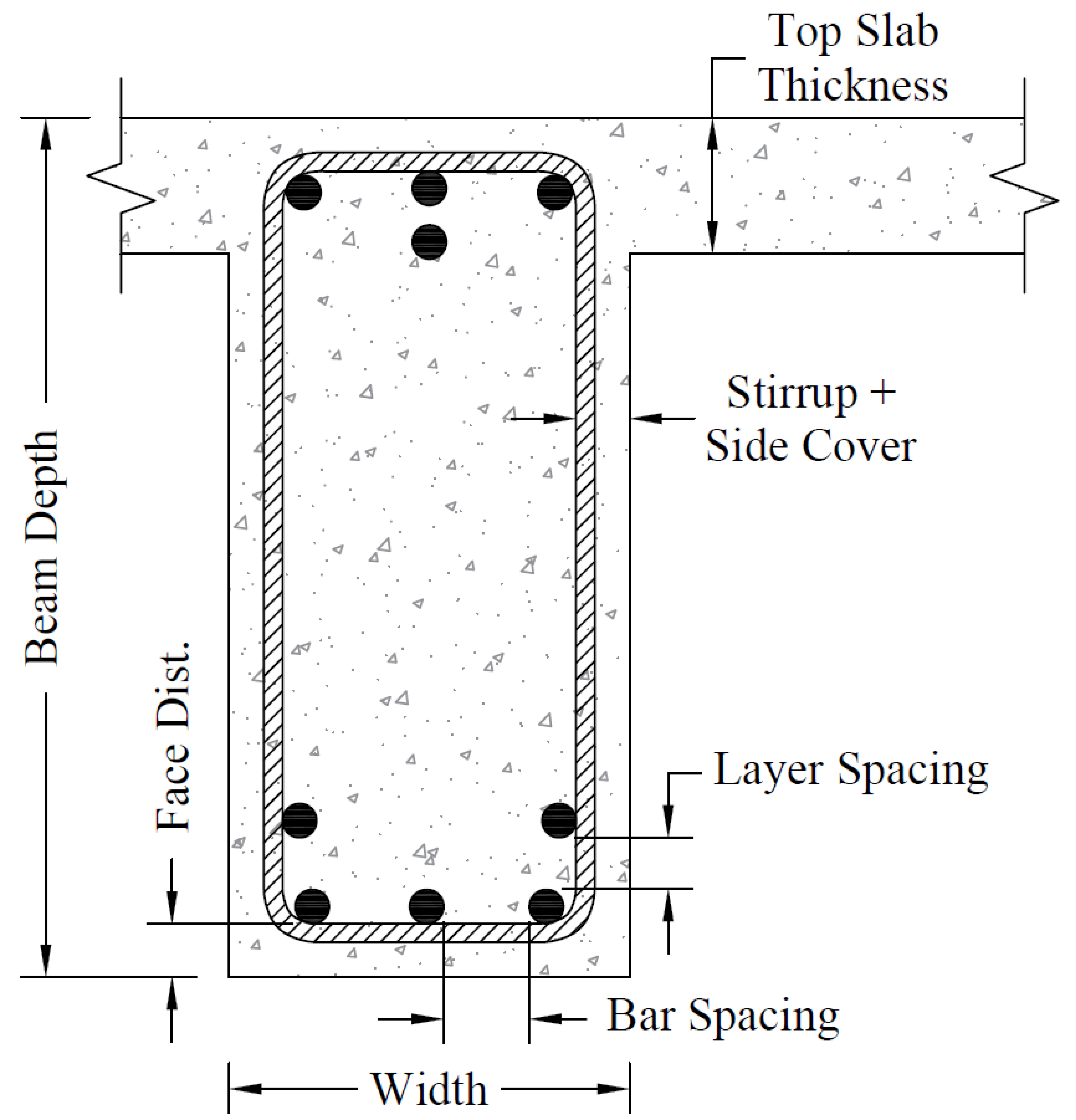
Figure 2.29 - Detail Reinforcement in Longitudinal Beams
2.5.1.2. Development Length Computation
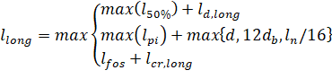
Bar-length computations are performed for two-way slabs and longitudinal beams. For top reinforcement at the supports, the length for long bars is given by:
| Eq. 2-86 |
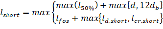
and length for short bars is given by:
| Eq. 2-86 |
where: | ||
• max (l50%) | = | maximum distance to the points of 50% demand, |
• max (lpi) | = | maximum distance to the points of inflection (P.I.), |
• ld = bar development length182,
• d = effective depth,
• db = bar diameter,
• ln = clear span length,
• lfos = distance to the face of support (column),
• lcr = minimum code prescribed extension.
These bar lengths are then compared and adjusted if necessary to meet the minimum extension requirements for reinforcement specified by the code.183 Additionally the program may select continuous top bars in those spans where steel is required by calculation in mid-span at top.
If the computed bar lengths overlap, it is recommended that such reinforcement be run continuously. The printed bar lengths do not include hooks or portions of bars bent down into spandrel beams or other bar-bend configurations. If a bar starts (or ends) at a column support the length of the bar is measured from (or to) the center line of the column. The selection of bar lengths for positive reinforcement for flat plates, flat slabs, and beam-supported slabs, is based strictly on the minimum values of the code.
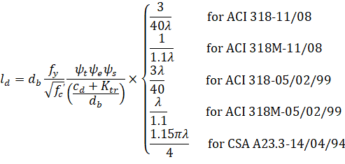
The development length depends on the following factors: concrete cover, minimum transverse reinforcement, special transverse reinforcement, layer location bar size and bar clear spacing. The development length is calculated from the general expression184 below, but not less185 than 12 in [300 mm].
| Eq. 2-99 |
where: | ||
• Ψt | = | reinforcement location factor equal to 1.3 if more than 12 in [300 mm] of fresh concrete is cast in the member below the development length or splice, or equal to 1.0 otherwise, |
• Ψe | = | coating factor equal to 1.0 for uncoated reinforcement; for epoxy coated reinforcement with covers less than 3db or clear spacing less than 6db the factor is equal to 1.5 and for all other epoxy coated bars it equals 1.2, |
• Ψs | = | reinforcement size factor equal to 1.0 for bars #7 [22] and larger or equal to 0.8 for bars #6 [19] and smaller if ACI 318 [ACI 318M] is selected; for CSA A23.3 the factor is equal to 1.0 for bars 25M and larger or equal to 0.8 for bars 20M and smaller, |
• λ | = | lightweight aggregate concrete factor equal to 1.0 for normal concrete and: |
0.75 for lightweight concrete per ACI 318-14, ACI 318-11 and ACI 318-08 | ||
1.3 for lightweight concrete per ACI 318-05/02/99 | ||
1.3 for low density concrete per CSA A23.3-14/04/94 | ||
1.2 for semi low density concrete per CSA A23.3-14/04/94 | ||
• Ktr | = | transverse reinforcement index conservatively assumed zero, |
• cb = smaller of the distance from bar surface to the closest concrete surface and one-half (two thirds for CSA186) center-to-center bar spacing187.
Additionally, the product of ΨtΨe is not taken greater than 1.7 and the development length, ld, is reduced188 by the factor of As,req to As,prov where the provided area of flexural reinforcement, As,prov, exceeds the area required by analysis, As,req.
The final calculated or minimum development length for each bar is tabulated in the design results section of the program results report. In two-way slab systems without beams, the development length presented is often controlled by the minimum development length.
Where flexural reinforcement is terminated in a tension zone, spSlab and spBeam provide a warning to require an extension of the bar beyond what is required for flexure. For ACI code, the shear capacity at the cutoff point for each bar is evaluated for satisfying the shear demand does not exceed permissible shear limit189. Final bar length shall be extended beyond the minimum reported to meet one of the three conditions outlined in ACI 318190.
2.5.2. Structural Integrity Reinforcement
Enhancing redundancy and ductility is necessary in the event of damage to a major supporting element resulting from an abnormal shock or blast loading event.
Minor changes in reinforcement detailing typically result in substantial enhancement in the overall integrity of a structure by confining the resulting damage to a small area and improving the resistance to progressive collapse.
The ACI code requires all bottom bars in the column strip to extend continuously (or with splices) in the entire span and at least two of these bars to pass within the column core and to be anchored at exterior supports191. In continuous beams, including longitudinal beams in two-way slab systems, spSlab and spBeam produce, in design mode, reinforcement that satisfies ACI requirements for structural integrity. In perimeter (exterior) beams, at least one sixth of the negative tension reinforcement and not less that two bars are continuous192. Also, at least one fourth of the positive tension reinforcement and not less than two bars are continuous in all beams193.
For the CSA code, the program performs calculation of the amount of integrity reinforcement at slab column connections in design mode. The integrity reinforcement is required for slabs without beams. Integrity reinforcement is not required if there are beams containing shear reinforcement in all spans framing into the column. Otherwise, the sum of all bottom reinforcement connecting the slab to the column on all faces of the periphery should consist of at least two bars and meet the condition194:
| Eq. 2-101 |
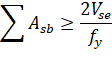
where Vse is the larger of shear force transmitted to column or column capital due to specified (unfactored) loads and shear force corresponding to twice the self-weight of the slab.
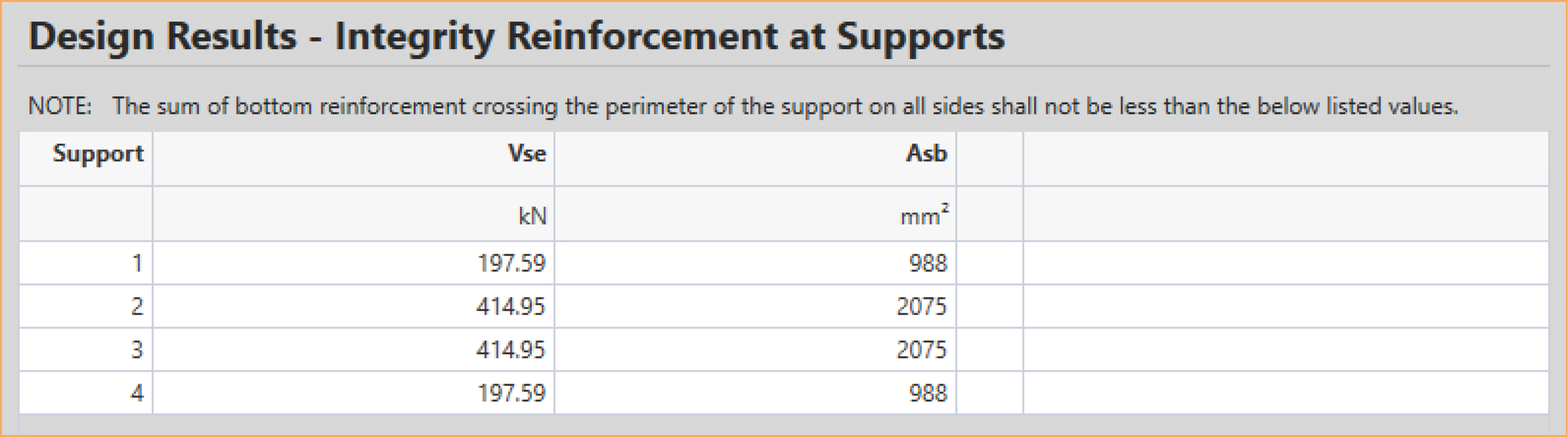
Figure 2.30 - Integrity Reinforcement at Supports
2.5.3. Corner Reinforcement
The program performs calculation of the amount of reinforcement in exterior corners of slabs with stiff edge beams (α greater than 1.0)195. This reinforcement is required within a region equal to 1/5 of the shorter span. The amount of corner reinforcement is calculated from the moment per unit width intensity corresponding to the maximum positive moment in span. The code allows the corner reinforcement to be placed at top and bottom of the slab in bands parallel to the sides of the slab edges.