6
In this chapter several examples are presented to demonstrate capabilities of the program. Generally program results match closely the results found in the referenced text books. When discrepancies are observed, they result from variations in assumptions and solutions methods, and numerical accuracy.
Both beams/one-way slab systems as well as two-way slab systems are presented in the examples. The output of beams/one-way slab examples shows that spBeam program was used to solve them. This is to illustrate that spBeam program is available as a limited version of spSlab including only beams/one-way slab capabilities.
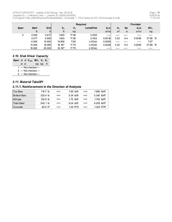
6.1Example 1 Spandrel Beam with Moment Redistribution
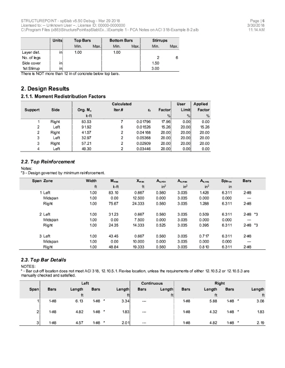
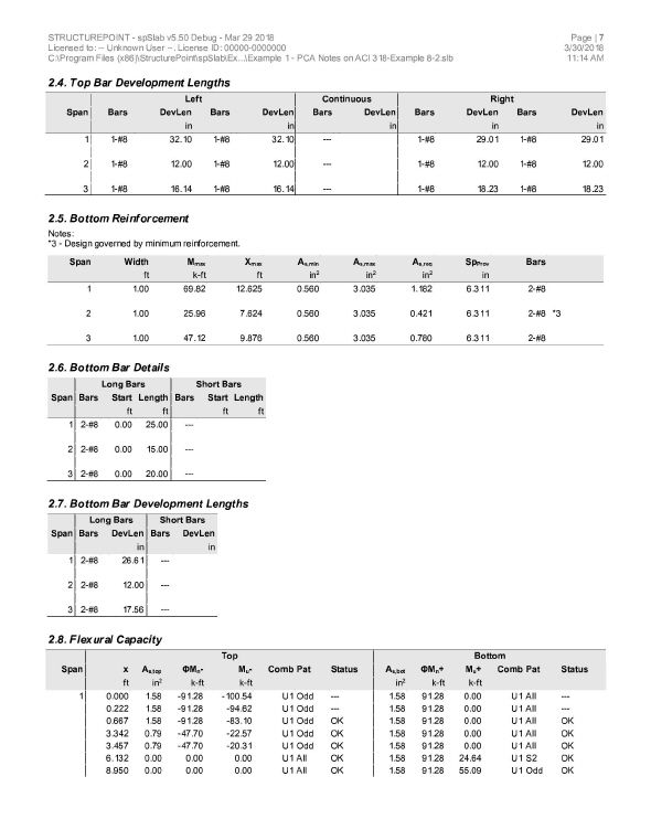
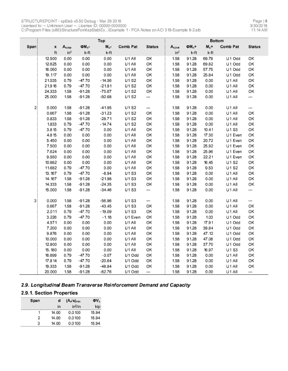
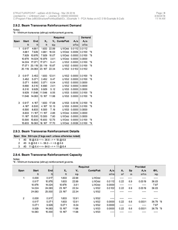
Determine the required reinforcement for the spandrel beam at an intermediate floor level as shown, using moment redistribution to reduce total reinforcement required. (Note: the self weight is already included in the specified dead load below.) This example refers to Example 8-2 from PCA Notes on ACI 318 Building Code Requirements for Structural Concrete.
Columns: 16 ´ 16 in.
Story height: 10 ft
Spandrel beam: 12 ´ 16 in.
f¢c = 4000 psi
fy = 60,000 psi
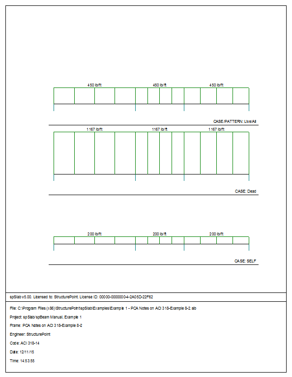
DL = 1167 lb/ft
LL = 450 lb/ft
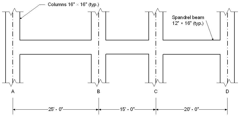
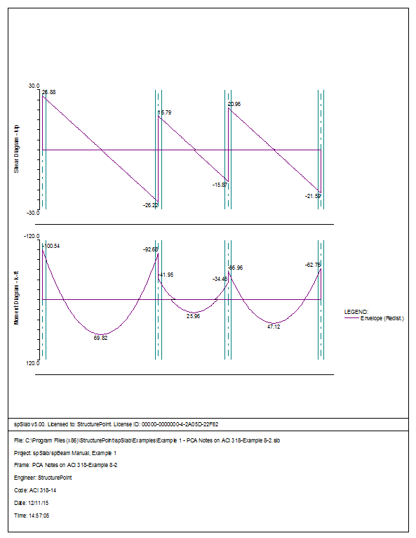
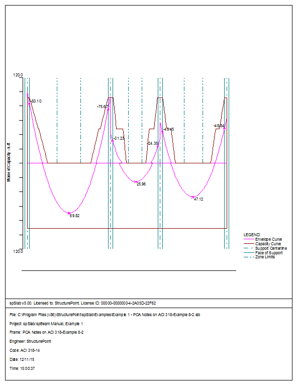
Figure 6.1 Example spandrel beam problem
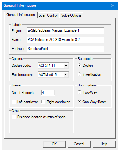
1.From the Input menu, select General Information. A dialog box appears.
–In the Labels section, input the names of the project, frame, and engineer.
–In the Frame section, input 4 for No of supports.
–In the Floor System section, click the radial button next to One way / beam.
–Leave all other options in the General Information tab to their default settings of ACI 318-14 design code, ASTM A615 reinforcement, and Design run mode option.
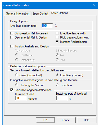
–In the Solve Options tab, click the check box next to Moment Redistribution. Press Ok.
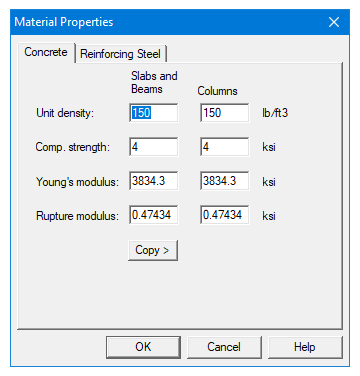
2.Nothing needs to be changed in the Material Properties dialog box.
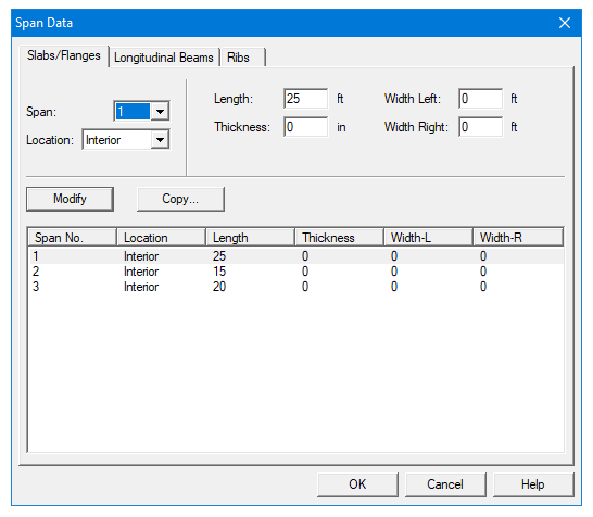
3.From the Input menu, select Spans. A dialog box appears.
–Under the Slabs/Flanges tab, input 25 for Length, 0 for Thickness, and 0 for Width Left and Width Right. Press Modify.
–Press the drop down arrow next to Span and select Span 2. Input 15 for Length, 0 for Thickness, and 0 for Width Left and Width Right. Press Modify.
–Press the drop down arrow next to Span and select Span 3. Input 20 for Length, 0 for Thickness, and 0 for Width Left and Width Right. Press Modify.
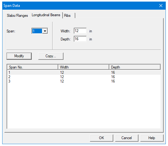
–Select the Longitudinal Beams tab. Input 12 for Width and 16 for Depth. Press Modify.
–Press Copy. Press the Check All button. Press Ok.
–Press Ok again.
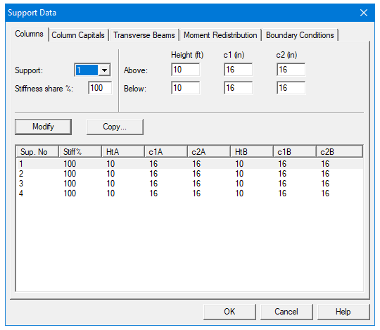
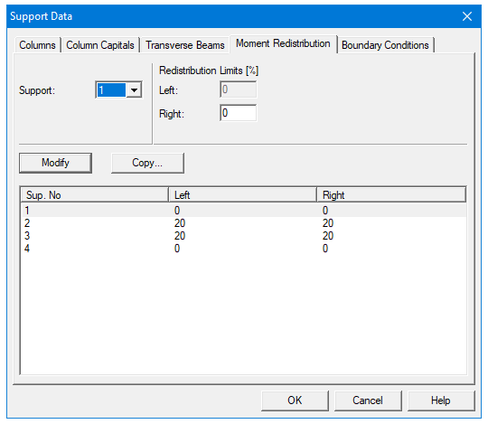
4.From the Input menu, select Supports. A dialog box appears.
–Under the Columns tab, input 16 for both the c1 and c2 values in both the Above and Below rows. Press Modify. (Note: the default Height Above and Height Below values of 10 are correct.)
–Press Copy. Press the Check All button. Press Ok.
–Under the Moment Redistribution tab, click on Support 2 in the list in the bottom half of the Support Data dialog box.
–Input 20 for both the Left and Right Redistribution Limits. Press Modify.
–Press Copy. Click the check box next to Span 3. Press Ok.
–Press Ok again.
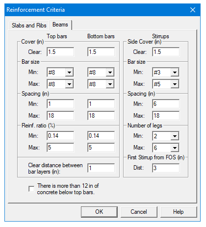
5.From the Input menu, select Reinforcement Criteria. A dialog box appears.
–Under the Beams tab, select #8 for Max Bar size for Top bars and Bottom bars.
–Press Ok.

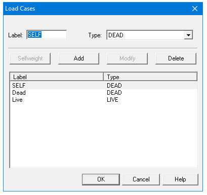
6.From the Input menu, select Load Cases. A dialog box appears.
–Since we are not considering lateral forces, click on Wind in the Label column on the list in the bottom half of the Load Cases dialog box and press the Delete button.
–Click on EQ in the Label column and press the Delete button. Press Ok.
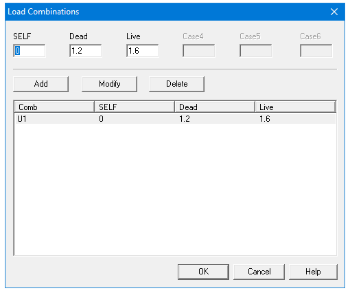
7.From the Input menu, select Load Combinations. A dialog box appears.
–Delete all the load combinations by clicking anywhere on the list in the bottom half of the Load Combinations dialog box and pressing the Delete button. Repeat this procedure until all the load combinations are gone.
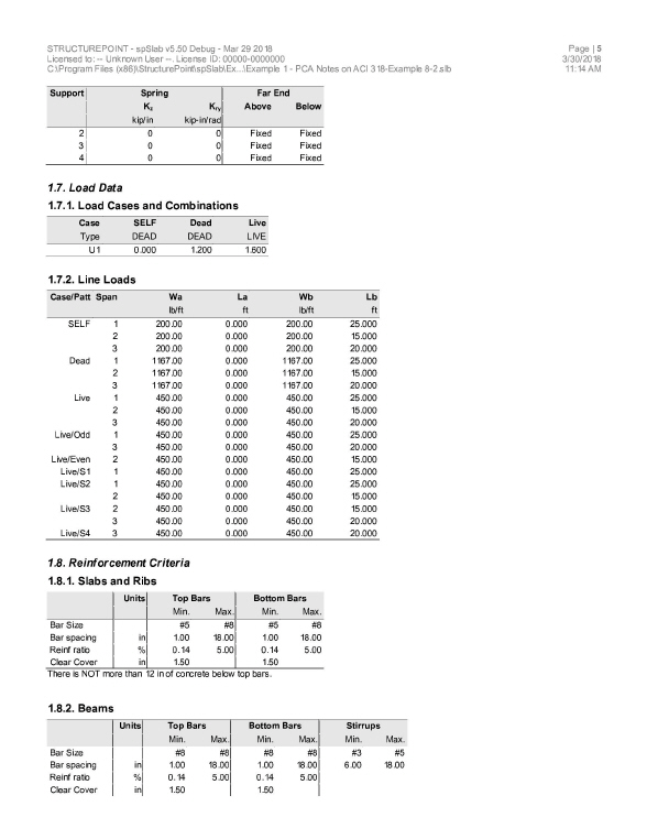
–Input 0 in the SELF field, 1.2 in the Dead field, and 1.6 in the Live field. Press Add.
–Press Ok.
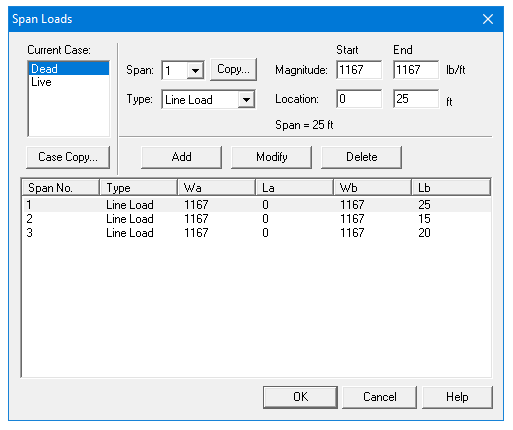
8.From the Input menu, select Span Loads. A dialog box appears.
–Press the drop down arrow next to Type, and select Line Load.
–Input 1167 for both the Start and End Magnitude.
–Input 25 for the End Location. Press Add.
–Use the drop down arrow next to Span to select Span 2. Keep the Start and End Magnitudes of 1167 lb/ft but change the End Location to 15. Click the Add button.
–Again use the drop down arrow next to Span to select Span 3. Keep the Start and End Magnitudes of 1167 lb/ft but change the End Location to 20. Click the Add button
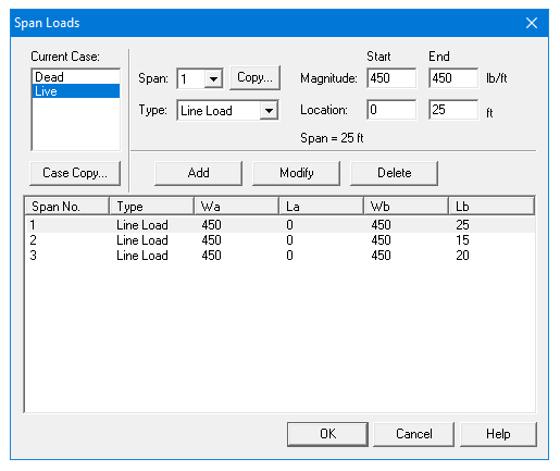
9.In the top left corner of the Span Loads dialog box, there is a section called Current Case. Click on Live.
–Use the drop down arrow next to Span to select Span 1.
–Making sure that Line Load is still the selected Load Type, input 450 for both the Start and End Magnitude.
–Input 25 for the End Location. Press Add.
–Use the drop down arrow next to Span to select Span 2. Keep the Start and End Magnitudes of 450 lb/ft but change the End Location to 15. Click the Add button.
–Again use the drop down arrow next to Span to select Span 3. Keep the Start and End Magnitudes of 1167 lb/ft but change the End Location to 20. Click the Add button
–Press Ok.
10.From the Solve menu, select Execute. Press Close.
11.From the Solve menu, select Results.
–Use the explorer to browse through the results tables.
–Use the ARROW keys or the mouse wheel to browse through different parts of the table quickly. Press the Close button to close the spRESULTS.
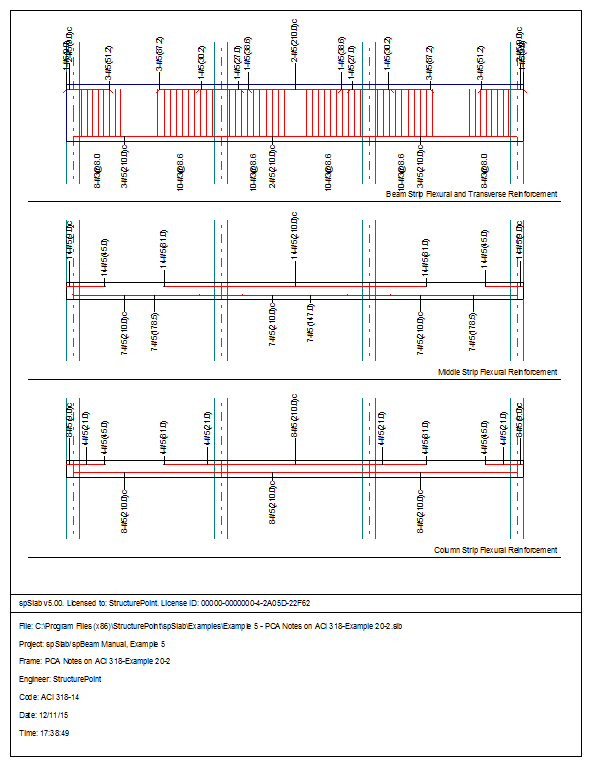
6.1.5Viewing and Printing Results
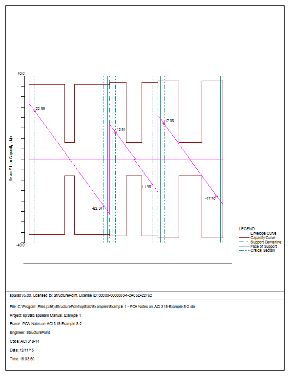
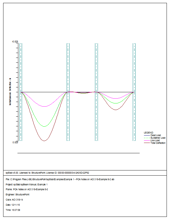
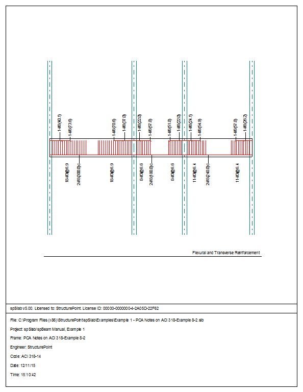
12.To view diagrams, select Loads, Internal Forces, Moment Capacity, Shear Capacity, Deflection, or Reinforcement from the View menu. Right click in any of these diagrams to get new copy, printing, or display options.
13.You may print the results report by using the spReporter module. To print any of the diagrams you selected to view, use the Print Preview command found by right clicking in the diagram’s window. After viewing the results, you may decide to investigate the input beams under the same loads but with a modified reinforcement configuration.
14.From the Input menu, select General Information. In the General Information dialog box change the Run Mode option to InvestigationDo not change any of the other options. Press Ok
15.From the Input menu, select the different commands under Reinforcement Criteria and Reinforcing Bars to modify the reinforcement configuration computed by the program.
16.Repeat steps 10 and subsequent to perform the investigation and view the results.


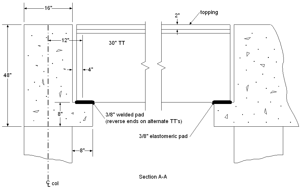
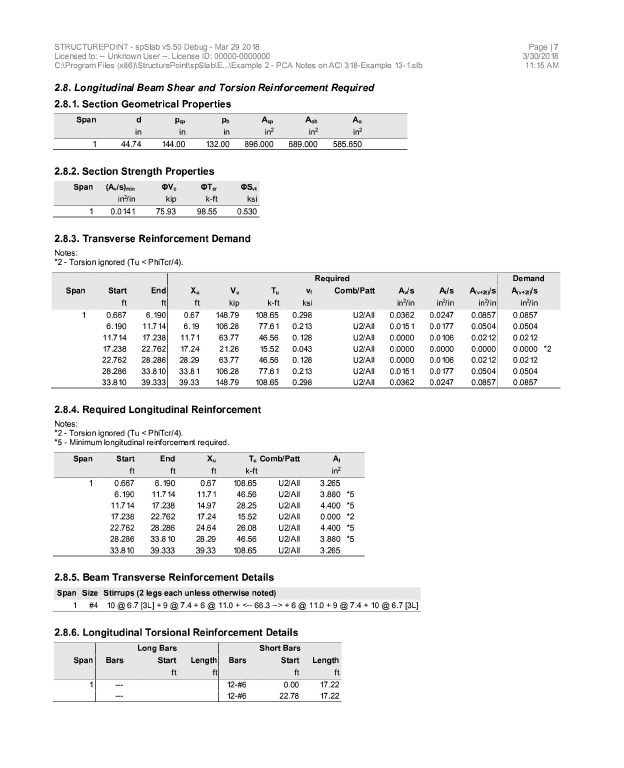
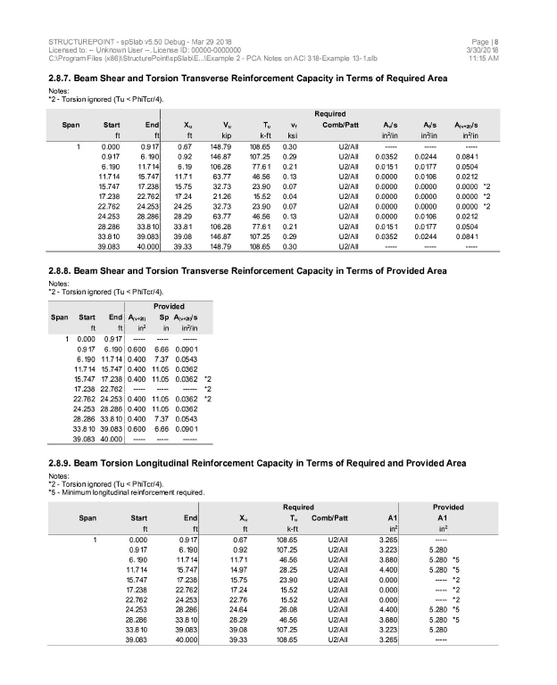
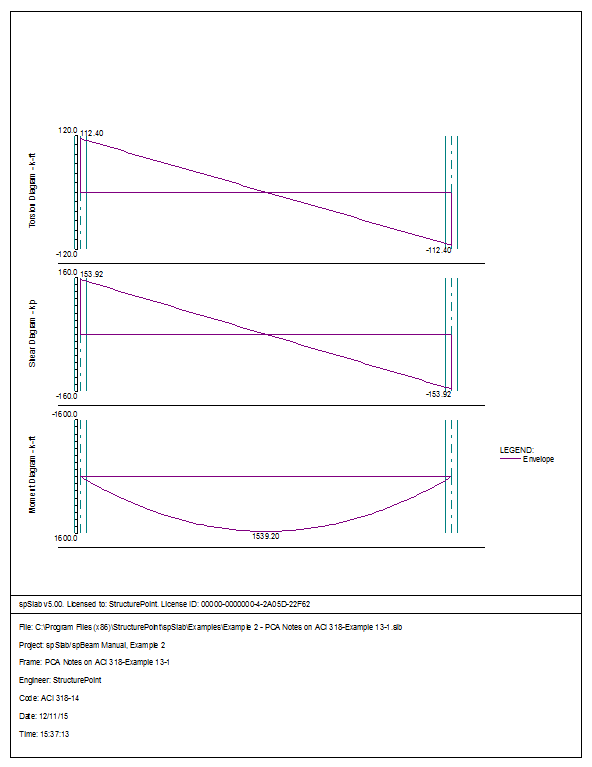
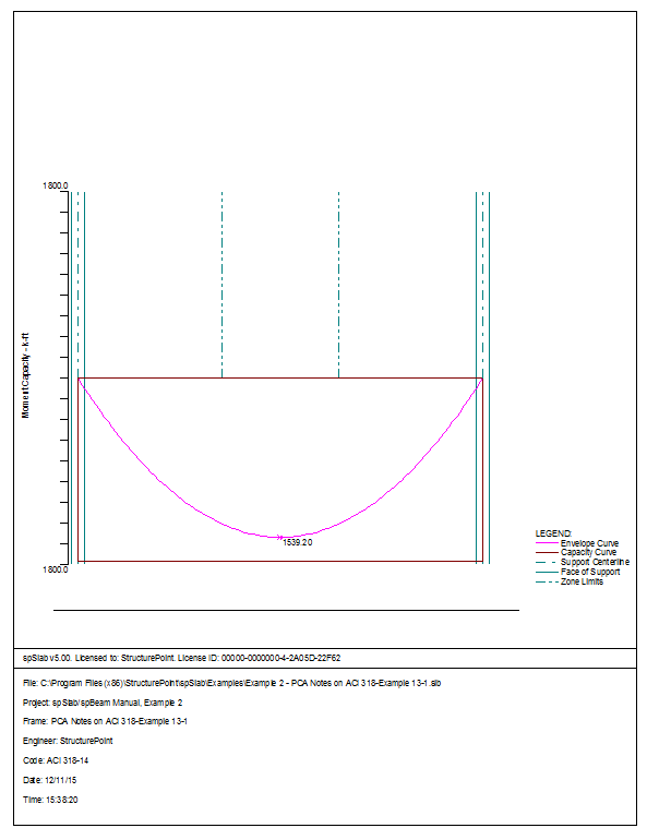
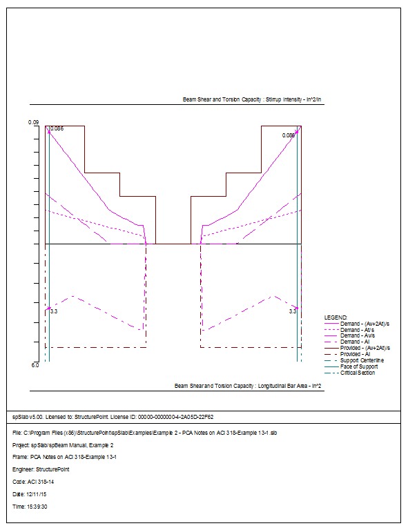
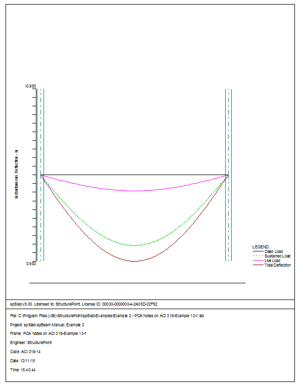
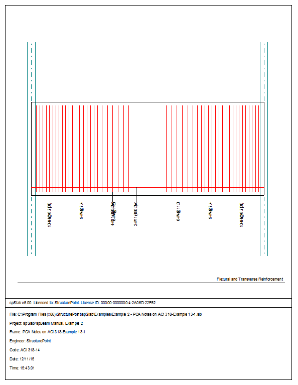
6.2Example 2 Spandrel Beam with Torsion
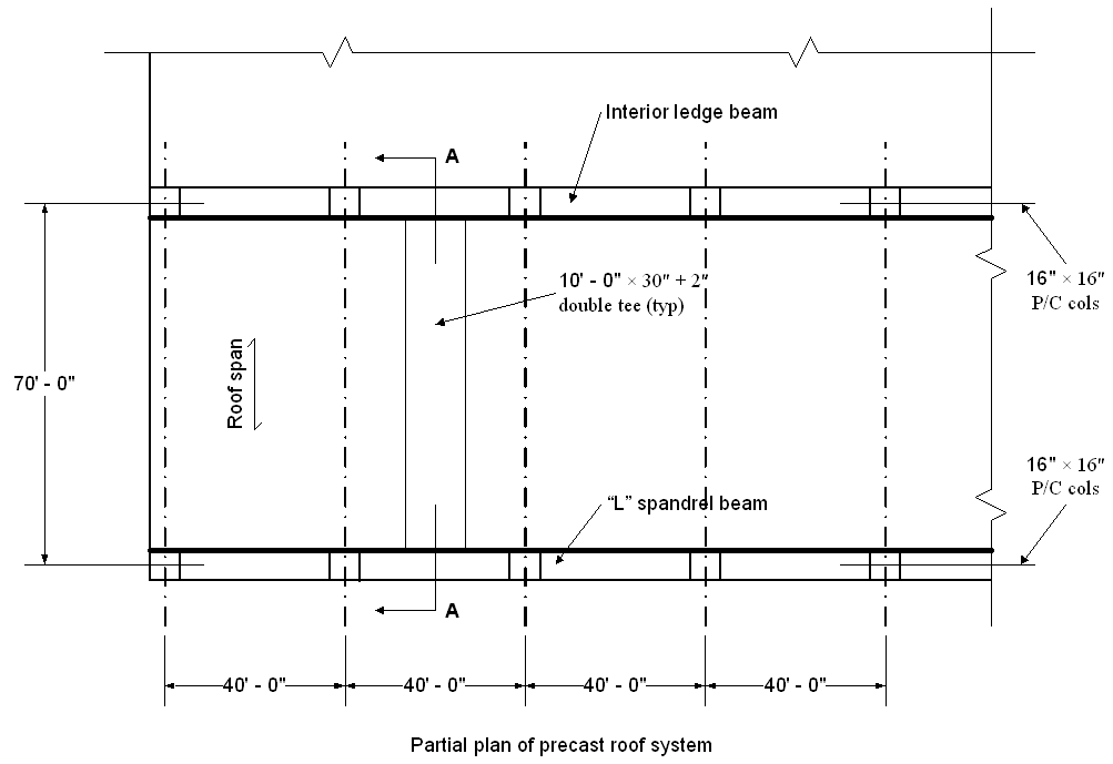
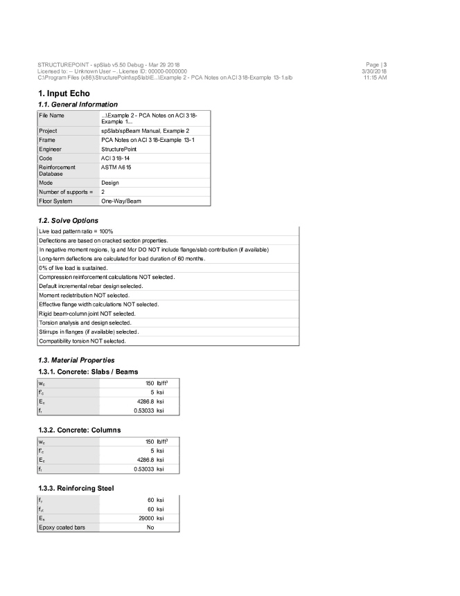
Design a precast, nonprestressed concrete spandrel beam for combined shear and torsion. Roof members are simply supported on spandrel ledge. Spandrel beams are connected to columns to transfer torsion. Continuity between spandrel beams is not provided. This example refers to Example 13-1 from PCA Notes on ACI 318 Building Code Requirements for Structural Concrete.
Design Criteria:
Live load = 30 lb/ft2
Dead load = 90 lb/ft2 (double tee + topping + insulation + roofing)
f¢c = 5000 psi (wc = 150 pcf)
fy = 60,000 psi
Roof members are 10 ft wide double tee units, 30 in. deep with 2 in. topping.. Design of these units is not included in this design example. For lateral support, alternate ends of roof members are fixed to supporting beams.
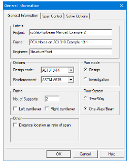
1.From the Input menu, select General Information. A dialog box appears.
–In the Labels section, input the names of the project, frame, and engineer.
–In the Frame section, input 2 for No of supports.
–In the Floor System section, click the radial button next to One way / beam.
–Leave all other options in the General Information tab to their default settings of ACI 318-14 design code, ASTM A615 reinforcement, and Design run mode option.
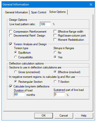
–In the Solve Options tab, click the check box next to Torsion Analysis and Design.
–Under Torsion type, click the radial button next to Equilibrium.
–Under the heading Stirrups in flanges, click the radial button next to Yes.
–Press Ok.
2.From the Input menu, select Material Properties. A dialog box appears.
–Input 5 for Comp. strength for both Slabs and Beams and Columns.
–Press Ok.

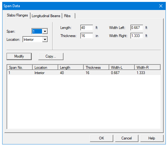
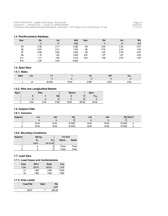
3.From the Input menu, select Spans. A dialog box appears.
–Under the Slabs/Flanges tab, input 40 for Length, 16 for Thickness, and 0.667 for Width Left and 1.333 Width Right. Press Modify.
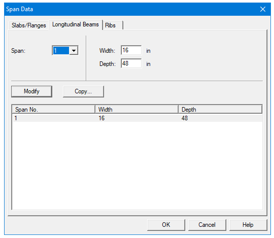
–Select the Longitudinal Beams tab. Input 16 for Width and 48 for Depth. Press Modify.
–Press Ok.
4.From the Input menu, select Supports. A dialog box appears.
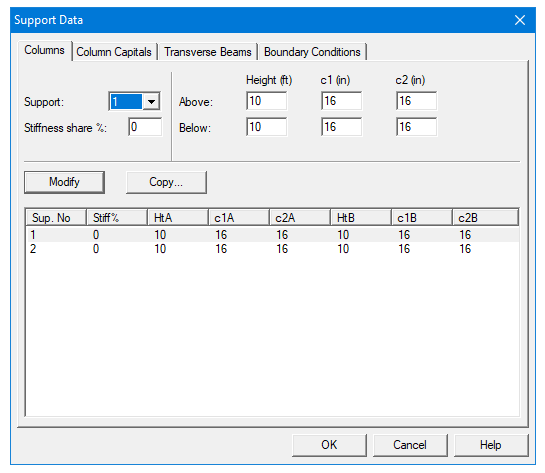
–Under the Columns tab, input 0 for Stiffness share %.
–Next, input 16 for both the c1 and c2 values in both the Above and Below rows. Press Modify. (Note: the default Height Above and Height Below values of 10 are correct.)
–Press Copy. Press the Check All button. Press Ok.
–Press Ok again.
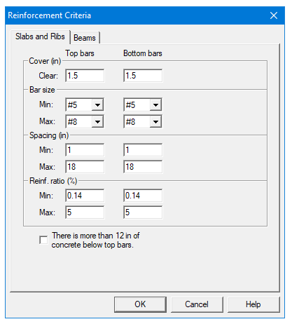
5.From the Input menu, select Reinforcement Criteria. A dialog box appears.
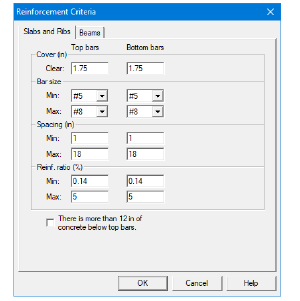
–Under the Slabs and Ribs tab, change the Clear Cover for both Top and Bottom bars to 1.75.
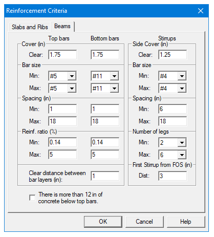
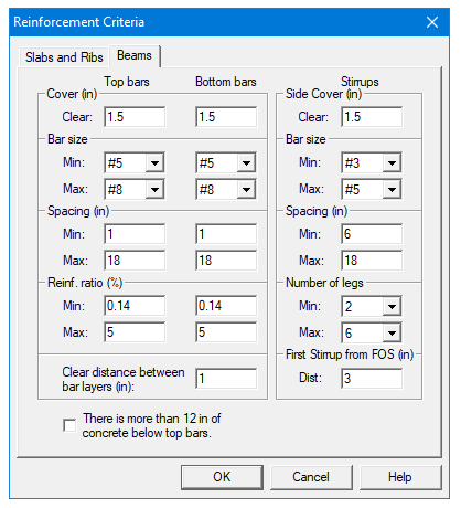
–Under the Beams tab, change the Clear Cover for both Top and Bottom Bars again to 1.75.
–Use the drop down arrow for Minimum Stirrup Bar Size to select #4.
–Press Ok.
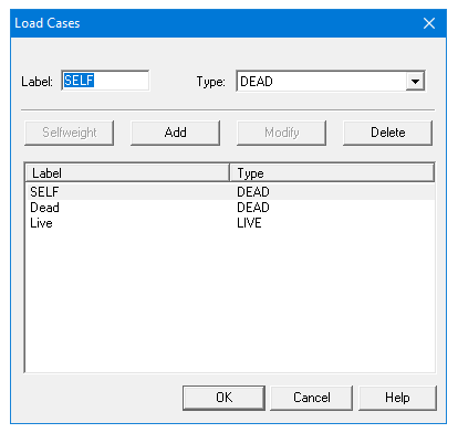
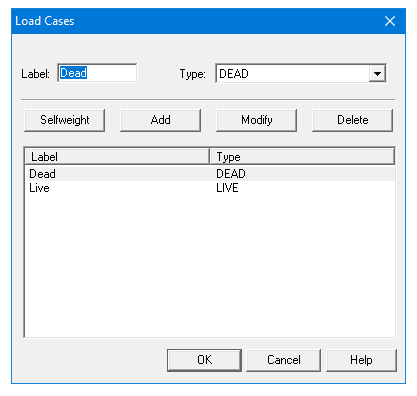
6.From the Input menu, select Load Cases. A dialog box appears.
–Since we are not considering lateral forces, click on Wind in the Label column on the list in the bottom half of the Load Cases dialog box and press the Delete button.
–Click on EQ in the Label column and press the Delete button.
–Press Ok.
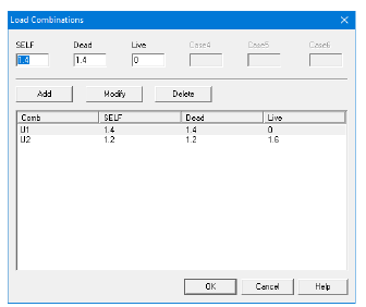
7.From the Input menu, select Load Combinations. A dialog box appears.
–Delete all the load combinations by clicking anywhere on the list in the bottom half of the Load Combinations dialog box and pressing the Delete button. Repeat this procedure until all the load combinations are gone.
–Input 0 in the SELF field, 1.2 in the Dead field, and 1.6 in the Live field. Press Add.
–Press Ok.
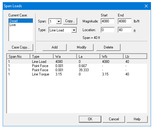
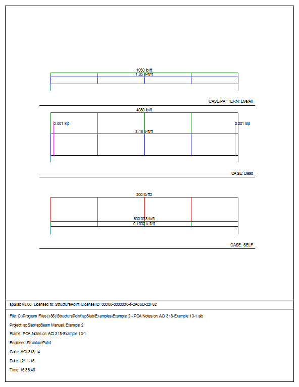
8.From the Input menu, select Span Loads. A dialog box appears.
–Press the drop down arrow next to Type, and select Line Load.
–Input 4080 for both the Start and End Magnitude. (Note: this value was obtained by converting the area loads on the roof and the beam’s self weight into line loads.)
Dead Load = Superimposed Load + Self Weight of Spandrel Beam =

–Input 40 for the End Location. Press Add.
–Critical section for torsion is at the face of the support because of concentrated torques applied by the double tee stems at a distance less than d from the face of the support. The critical section for shear is also at the face of support because the load on the spandrel beam is not applied close to the top of the member and because the concentrated forces transferred by the double tee stems are at a distance less than d from the face of support. A small dummy load of 0.001 kips at the face of support is therefore introduced in order to move the critical section for shear from the default location of d away from the support to the face of the support.
–Use the drop down arrow next to Type, and select POINT FORCE.
–Input 0.001 for the MAGNITUDE and 0.667 for the LOCATION. Press ADD.
–Use the drop down arrow next to Type, and select POINT FORCE.
–Input 0.001 for the MAGNITUDE and 39.333 for the LOCATION. Press ADD.
–Use the drop down arrow next to Type, and select Line Torque.
–Input 3.15 for both the Start and End Magnitude. (Note: this value was obtained by multiplying the superimposed line load by the moment arm of 12 in.)
Torsion Line Load (Dead) = 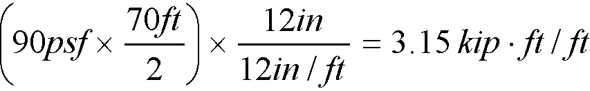
–Keep the End Location of 40 and press Add.
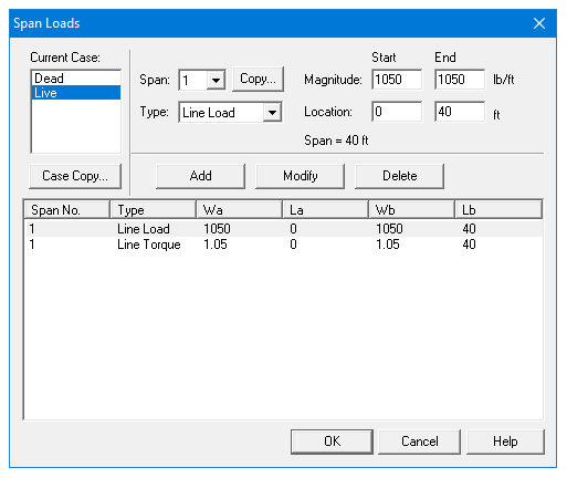
9.In the top left corner of the Span Loads dialog box, there is a section called Current Case. Click on Live.
–Use the drop down arrow next to Type to select Line Load. I
–Input 1050 for both the Start and End Magnitude. (Note: this value was obtained by converting the area loads on the roof to line loads on the beam.)
Live Load = 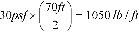
–Input 40 for the End Location. Press Add.
–Use the drop down arrow next to Type, and select Line Torque.
–Input 1.05 for both the Start and End Magnitude. (Note: this value was obtained by multiplying the live line load by the moment arm of 12 in.)
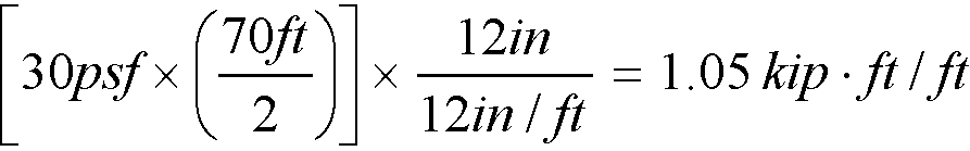
–Input 40 for the End Location. Press Add.
–Press Ok.
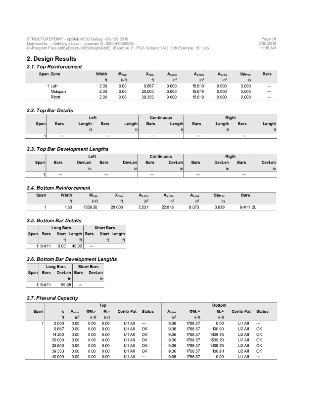
10.From the Solve menu, select Execute. Press Close.
11.From the Solve menu, select Results.
–Use the explorer to browse through the results tables.
–Use the ARROW keys or the mouse wheel to browse through different parts of the table quickly. Press the Close button to close the spRESULTS.
6.2.5Viewing and Printing Results
12.To view diagrams, select Loads, Internal Forces, Moment Capacity, Shear Capacity, Deflection, or Reinforcement from the View menu. Right click in any of these diagrams to get new copy, printing, or display options.
13.You may print the results report by using the spReporter module. To print any of the diagrams you selected to view, use the Print Preview command found by right clicking in the diagram’s window. After viewing the results, you may decide to investigate the input beams under the same loads but with a modified reinforcement configuration.
14.From the Input menu, select General Information. In the General Information dialog box change the Run Mode option to Investigation. Do not change any of the other options. Press Ok.
15.From the Input menu, select the different commands under Reinforcement Criteria and Reinforcing Bars to modify the reinforcement configuration computed by the program.
16.Repeat steps 10 and subsequent to perform the investigation and view the results.


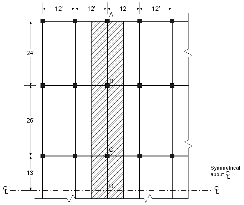
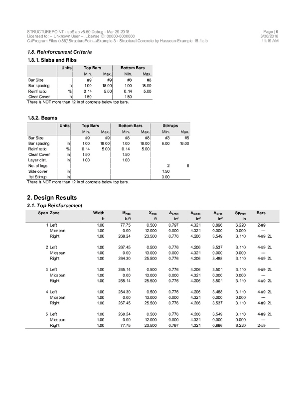
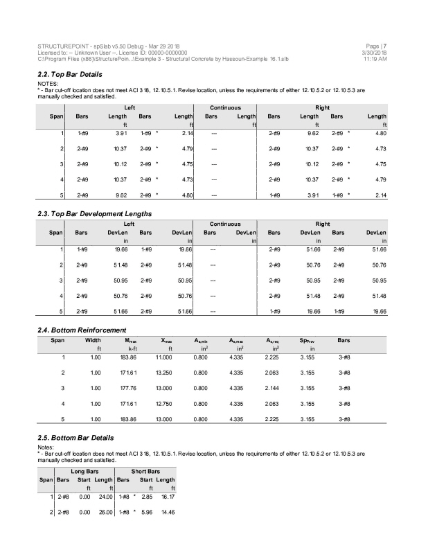
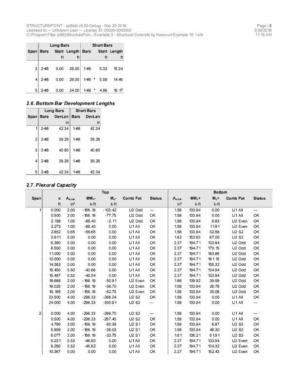
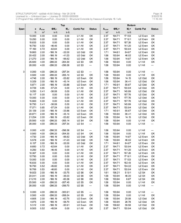
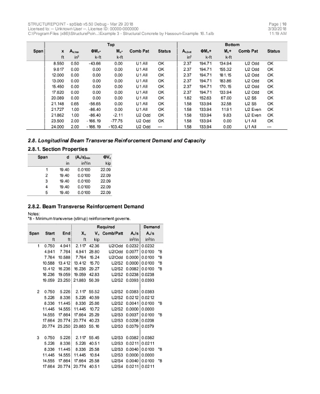
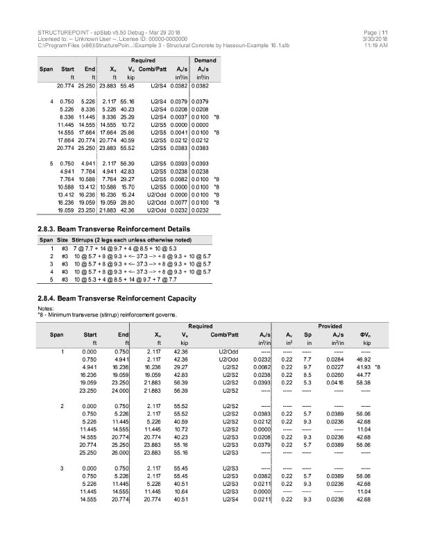
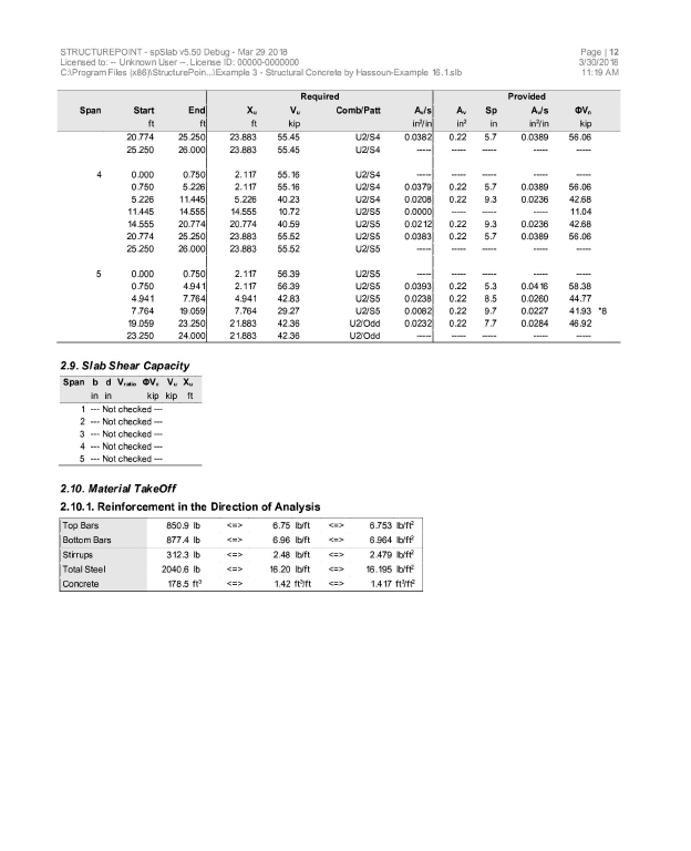
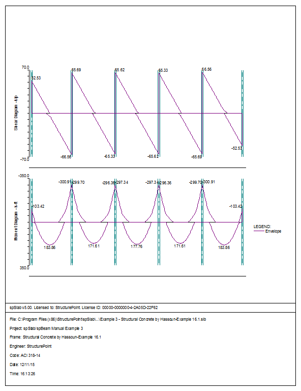
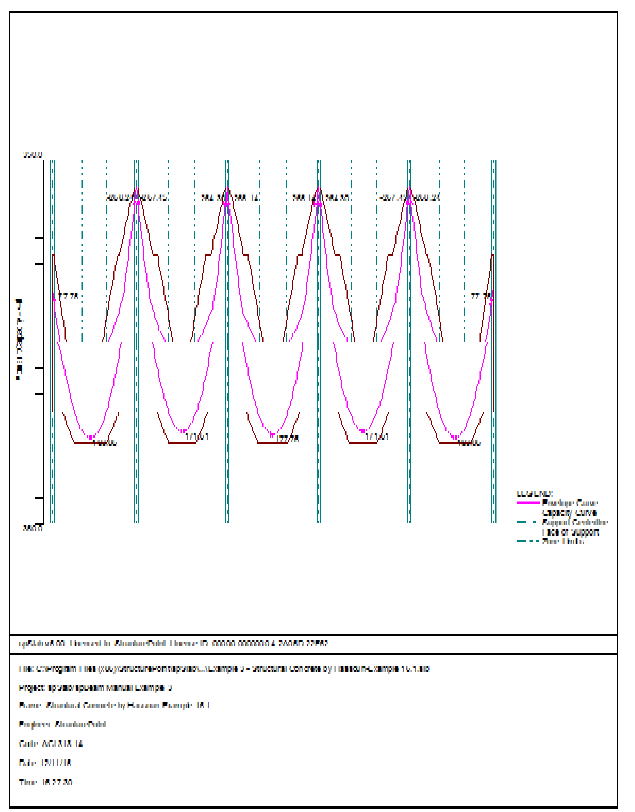
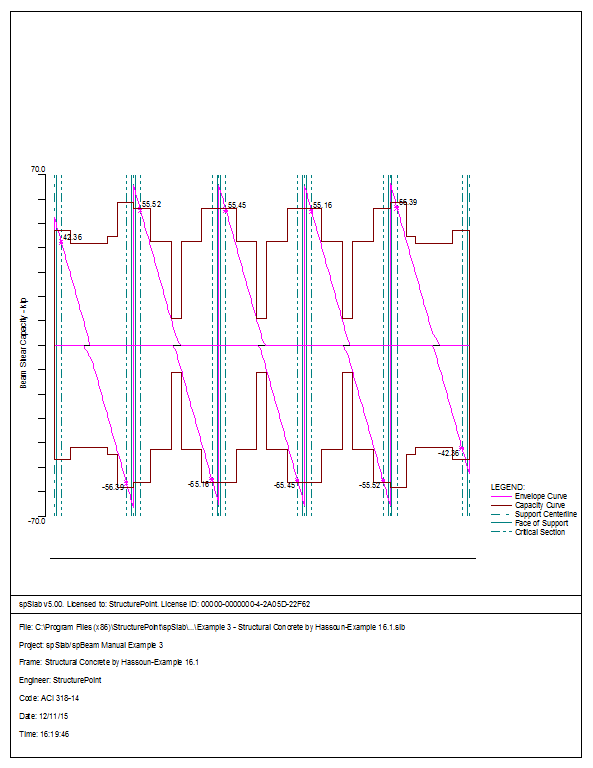
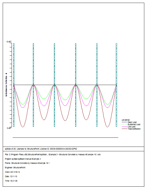
6.3Example 3 Design of a Continuous Beam
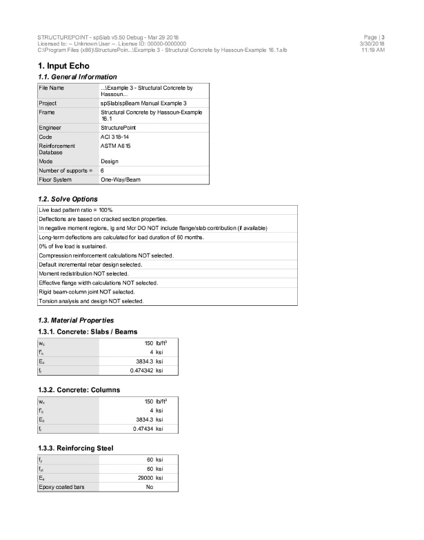
The system shown in the following figure consists of five spans symmetric about the centerline. We will be designing beam ABCD assuming that the other half of the beam will be loaded and designed the same way. All beams have a width of 12 in. and a depth of 22 in. – including the 5 in. thick deck. Span length and widths are shown in the figure. Columns have a 12 in. ´ 12in. cross-section and a length equal to a typical story height of 13 ft. The system will be analyzed and designed under a uniform live load of 130 psf and a dead load that consists of the slab system’s own weight plus 80 psf. Use f’c = 4 ksi, fy = 60 ksi, and gconcrete = 150 pcf. This example refers to example 16.1 from Structural Concrete: Theory and Design by Hassoun and Al-Manaseer, Third Edition, 2008.
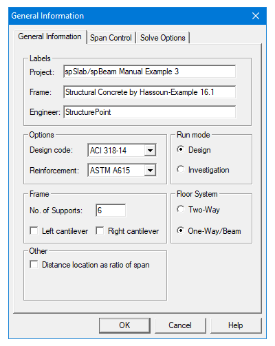
1.From the Input menu, select General Information. A dialog box appears.
–In the Labels section, input the names of the project, frame, and engineer.
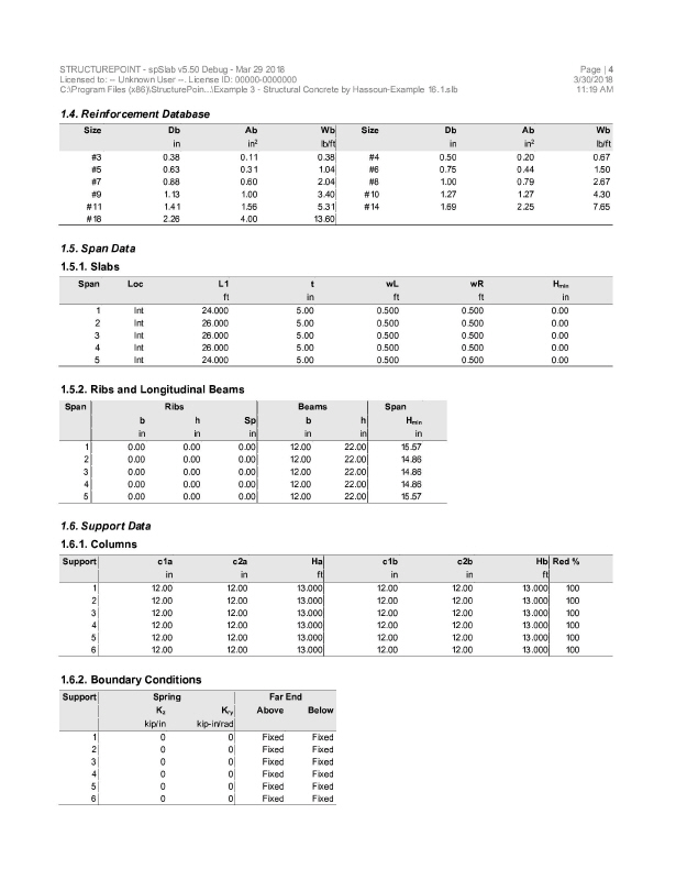
–In the Frame section, input 6 for No of supports as the spBeam models the entire continuous beam.
–In the Floor System section, click the radial button next to One-way / beam.
–Leave all other options in the General Information tab to their default settings of ACI 318-14 design code, ASTM A615 reinforcement, and Design run mode option.
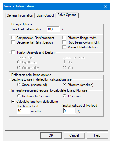
–In the Solve Options tab, keep the default settings. Press Ok.
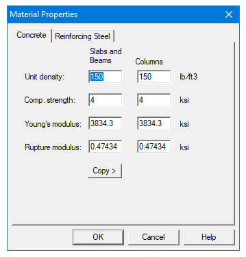
2.Nothing needs to be changed in the Material Properties menu.
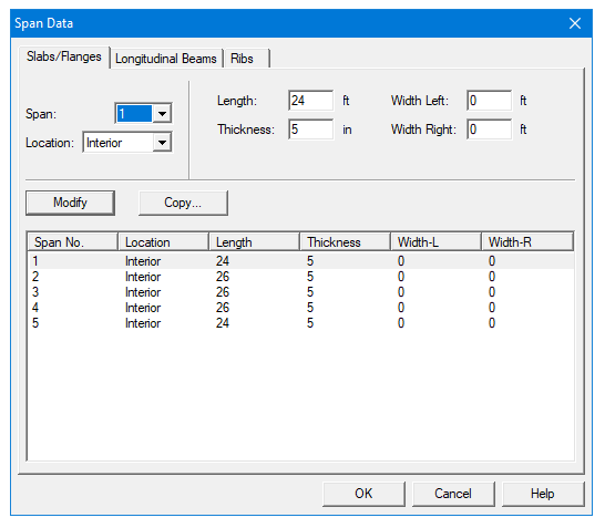
3.From the Input menu, select Spans. A dialog box appears.
–Under the Slabs/Flanges tab, input 24 for Length, 5 for Thickness, and 0 for Width Left and Width Right. Press Modify. (Note: Since the slab has no width, we must convert the area loads to line loads along the beam and also add the self-weight of the slab to the dead load. This calculation will be shown in Step 8.)
–Press Copy. Select the check box next to Span 5. Press Ok. This will give Span 5 the same geometry as Span 1.
–Press the drop down arrow next to Span and select Span 2. Input 26 for Length, 5 for Thickness, and 0 for Width Left and Width Right. Press Modify.
–Press Copy. Unselect the check box next to Span 1 and select the check boxes next to Spans 3 and 4. Press Ok.
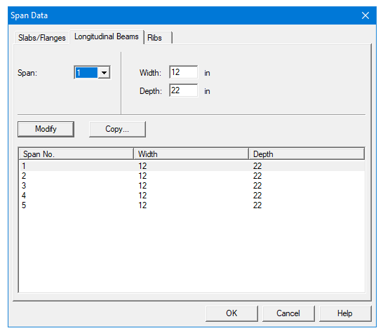
–Select the Longitudinal Beams tab. Input 12 for Width and 22 for Depth. Press Modify.
–Press Copy. Press the Check All button. Press Ok.
–Press Ok again.
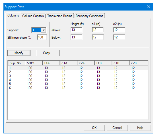
4.From the Input menu, select Supports. A dialog box appears.
–Under the Columns tab, input 13 for both Height Above and Height Below. Press Modify. (Note: the default c1 and c2 values for both the column above and below the support can be left alone since all the columns’ cross sections are 12 in. ´ 12 in.)
–Press Copy. Press the Check All button. Press Ok.
–Press Ok again.
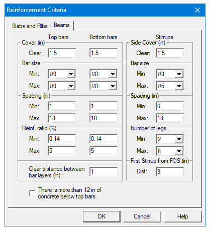
5.From the Input menu, select Reinforcement Criteria. A dialog box appears.
–Under the Beams tab, use the drop down arrows to change both the Min and Max Bar size for Top bars to #9.
–Use the drop down arrows to change both the Min and Max Bar size for Bottom bars to #8. Press Ok.
6.From the Input menu, select Load Cases. A dialog box appears.
–Since we are not considering lateral forces, click on Wind in the Label column on the list in the bottom half of the Load Cases dialog box and press the Delete button.
–Click on EQ in the Label column and press the Delete button. Press Ok.

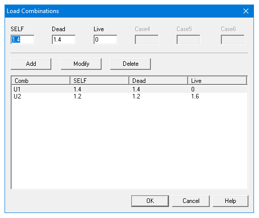
7.From the Input menu, select Load Combinations. A dialog box appears.
–Delete all the load combinations by clicking anywhere on the list in the bottom half of the Load Combinations dialog box and pressing the Delete button. Repeat this procedure until all the load combinations are gone.
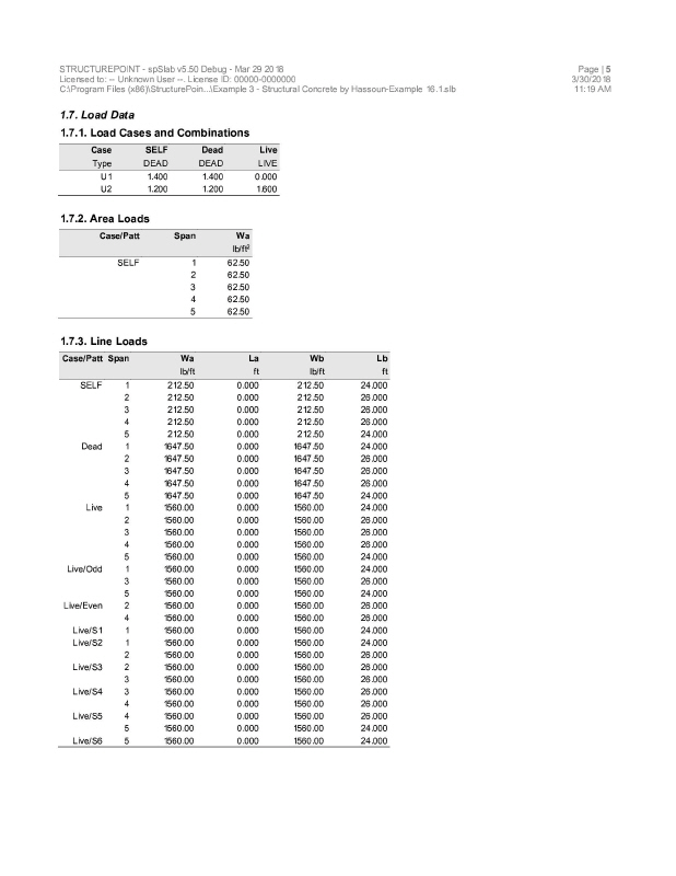
–Input 1.2 in the SELF field, 1.2 in the Dead field, and 1.6 in the Live field. Press Add.
–Press Ok.
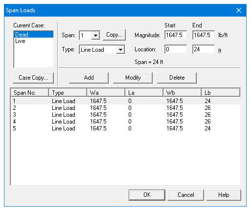
8.From the Input menu, select Span Loads. A dialog box appears.
–Press the drop down arrow next to Type, and select Line Load.
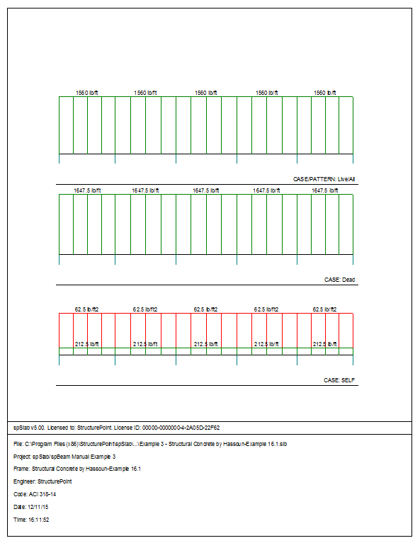
–Input 1647.5 for both the Start and End Magnitude. (Note: This value was obtained by converting the area loads of the of the slab’s self weight (without the beam) and superimposed dead load into a line load.)
Dead Load = 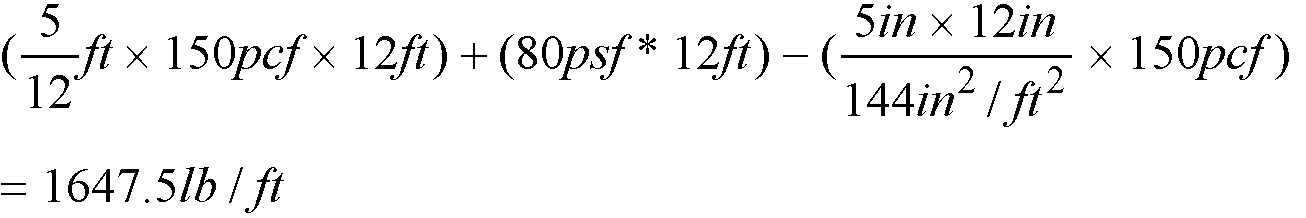
–Input 24 for the End Location. Press Add.
–Click on Span 1 on the list in the bottom half of the Span Loads dialog box. Press the Copy button. (Note: there is a Case Copy button that should not be pressed.)
–Click the check box next to Span 5 and press Ok.
–Back in the Span Loads dialog box, use the drop down arrow next to Span to select Span 2. Keep the Start and End Magnitudes of 1647.5 lb/ft but change the End Location to 26. Click the Add button.
–Click on Span 2 in the list at the bottom half of the Span Loads dialog box. Press the Copy button.
–Click the check boxes next to Span 3 and 4. Press Ok.
–
–
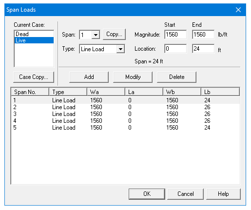
9.In the top left corner of the Span Loads dialog box, there is a section called Current Case. Click on Live.
–Use the drop down arrow next to Span to select Span 1.
–Making sure that Line Load is still the selected Load Type, input 1560 for both the Start and End Magnitude.
Live Load = 
–Input 24 for the End Location. Press Add.
–Click on Span 1 on the list in the bottom half of the Span Loads dialog box. Press the Copy button. (Note: the Case Copy button should not be pressed.)
–Click the check box next to Span 5 and press Ok.
–Back in the Span Loads dialog box, use the drop down arrow next to Spans to select Span 2. Keep the Start and End Magnitudes of 1560 lb/ft but change the End Location to 26. Click the Add button.
–Click on Span 2 in the list at the bottom half of the Span Loads dialog box. Press the Copy button.
–Click the check boxes next to Span 3 and 4. Press Ok.
–Press Ok again.
10.From the Solve menu, select Execute. Press Close.
11.From the Solve menu, select Results.
–Use the explorer to browse through the results tables.
–Use the ARROW keys or the mouse wheel to browse through different parts of the table quickly. Press the Close button to close the spRESULTS.
6.3.5Viewing and Printing Results
12.To view diagrams, select Loads, Internal Forces, Moment Capacity, Shear Capacity, Deflection, or Reinforcement from the View menu. Right click in any of these diagrams to get new copy, printing, or display options.
13.You may print the results report by using the spReporter module. To print any of the diagrams you selected to view, use the Print Preview command found by right clicking in the diagram’s window. After viewing the results, you may decide to investigate the input beams under the same loads but with a modified reinforcement configuration.
14.From the Input menu, select General Information. In the General Information dialog box change the Run Mode option to Investigation. Do not change any of the other options. Press Ok
15.From the Input menu, select the different commands under Reinforcement Criteria and Reinforcing Bars to modify the reinforcement configuration computed by the program.
16.Repeat steps 10 and subsequent to perform the investigation and view the results.


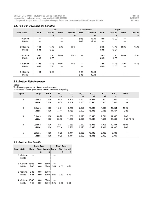
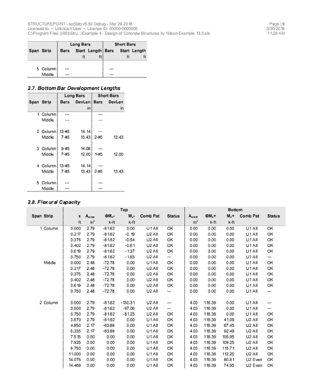
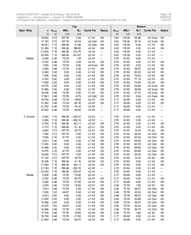
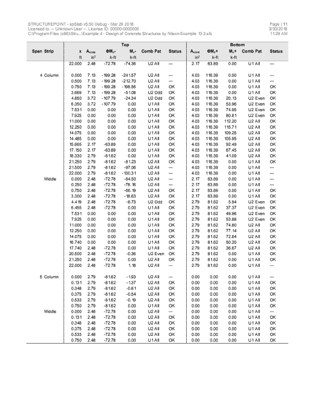
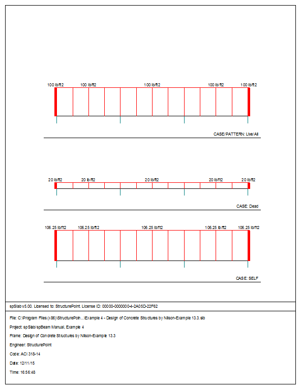
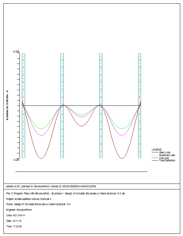
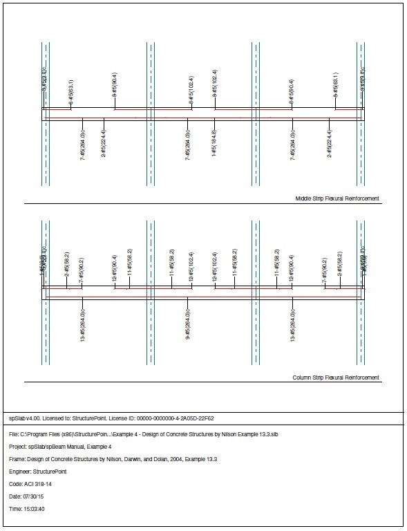
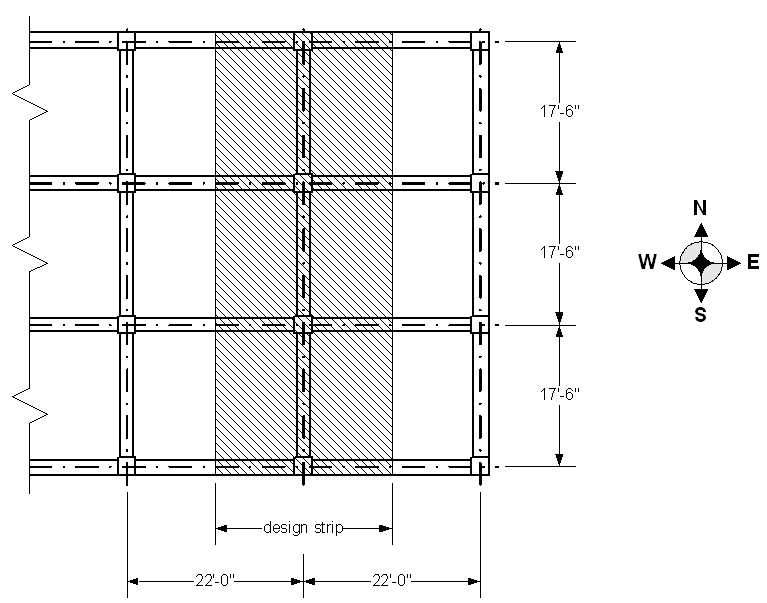
6.4Example 4 Flat Plate Floor System
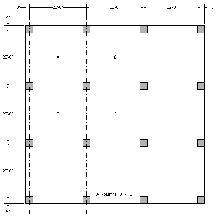
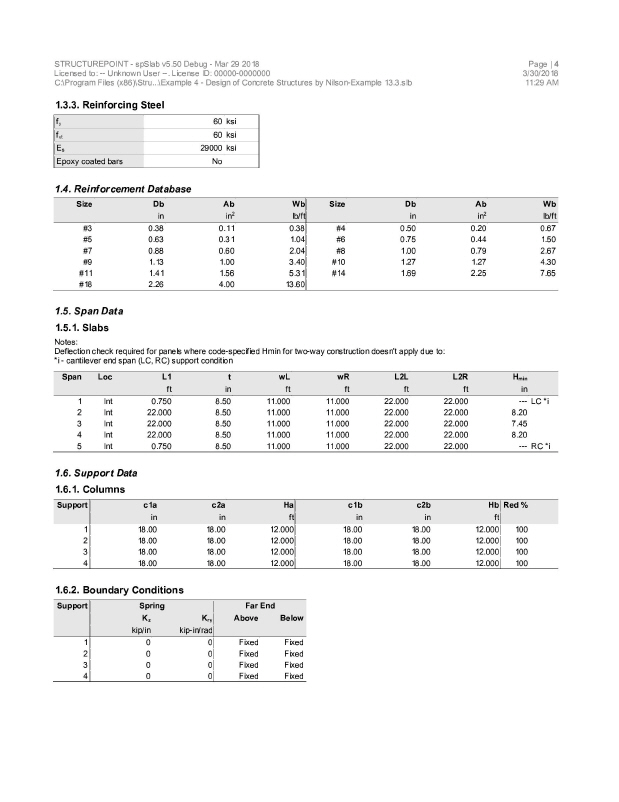
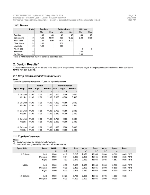
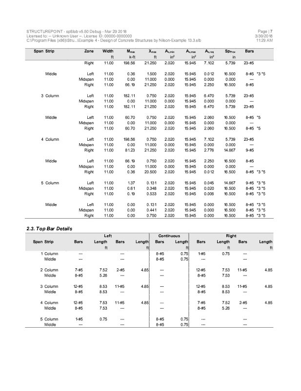
An office building is planned using a flat plate floor system with the column layout as shown in figure below. No beams, drop panels, or column capitals are permitted. Specified live load is 100 psf and dead load will include the weight of the slab plus an allowance of 20 psf for finish floor plus suspended loads. The columns will be 18 in. square, and the floor-to-floor height of the structure will be 12 ft. The slab thickness will be 8.5 in. according to ACI Code. Design the interior panel C, using material strengths fy = 60,000 psi and f’c = 4000 psi. Straight-bar reinforcement will be used. This example refers to Example 13-3 from Design of Concrete Structures by Nilson, Darwin, and Dolan, Thirteenth Edition, 2004.
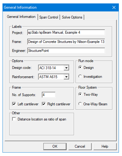
1.From the Input menu, select General Information. A dialog box appears.
–In the Labels section, input the names of the project, frame, and engineer.
–In the Frame section, input 4 for No of supports. Then, Click the check boxes next to LEFT CANTILEVER and RIGHT CANTILEVER.
–In the Floor System section, click the radial button next to Two-Way.
–Leave all other options in the General Information tab to their default settings of ACI 318-14 design code, ASTM A615 reinforcement, and Design run mode option.
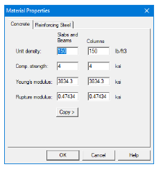
2.Nothing needs to be changed in the Material Properties menu.
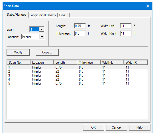
3.From the Input menu, select Spans. A dialog box appears.
–Under the Slabs/Flanges tab, for Span No. 1 input 0.75 for Length, 8.5 for Thickness, and 11 for Width Left and Width Right. Press Modify.
–Press Copy. Click the check box next to Span No. 5. Press Ok.
–Under the Slabs/Flanges tab, for Span No. 2 input 22 for Length, 8.5 for Thickness, and 11 for Width Left and Width Right. Press Modify.
–Click the check boxes next to Span No. 3, and Span No. 4. Press Ok.
–Press Ok again.
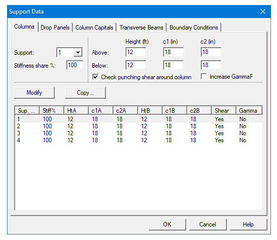
4.From the Input menu, select Supports. A dialog box appears.
–Under the Columns tab, input 12 for the Height in both the Above and Below rows.
–Input 18 for both the c1 and c2 values in both the Above and Below rows. Press Modify.
–Press Copy. Press the Check All button. Press Ok.
–Press Ok again.
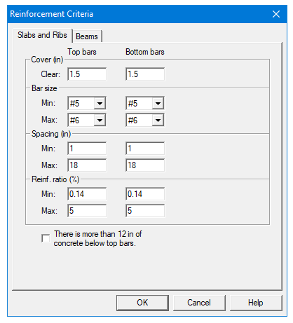
5.From the Input menu, select Reinforcement Criteria.
–Use the drop down arrow next to Max Bar Size for both Top Bars and Bottom Bars to select #6 bars.
–Press Ok.
6.From the Input menu, select Load Cases. A dialog box appears.
–Since we are not considering snow loads, click on Snow in the Label column on the list in the bottom half of the Load Cases dialog box and press the Delete button.
–Since we are not considering lateral forces, click on Wind in the Label column on the list in the bottom half of the Load Cases dialog box and press the Delete button.
–Click on EQ in the Label column and press the Delete button. Press Ok.

7.From the Input menu, select Load Combinations. A dialog box appears.
–Delete all the load combinations by clicking anywhere on the list in the bottom half of the Load Combinations dialog box and pressing the Delete button. Repeat this procedure until all the load combinations are deleted.
–Input 1.2 in the Self field, 1.2 in the Dead field, and 1.6 in the Live field. Press Add.
–Press Ok.

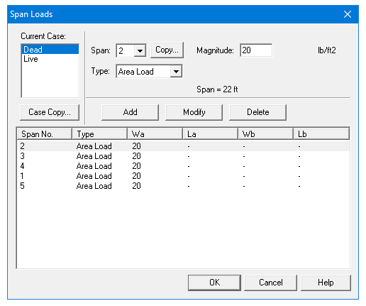
8.From the Input menu, select Span Loads. A dialog box appears.
–Input 20 for the Magnitude. Press Add.
–Press Copy. Press the Check All button. Press Ok.
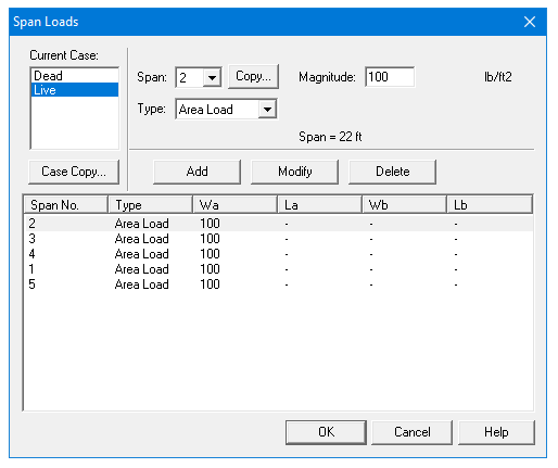
–In the top left corner of the Span Loads dialog box, there is a section called Current Case. Click on Live.
–Input 100 for Magnitude. Press Add.
–Press Copy. Press the Check All button. Press Ok.
–Press Ok again.
9.From the Solve menu, select Execute. Press Close.
10.From the Solve menu, select Results.
–Use the explorer to browse through result tables.
–Use the ARROW keys or the mouse wheel to browse through different parts of the table quickly. Press the Close button to close the spRESULTS.
6.4.5Viewing and Printing Results
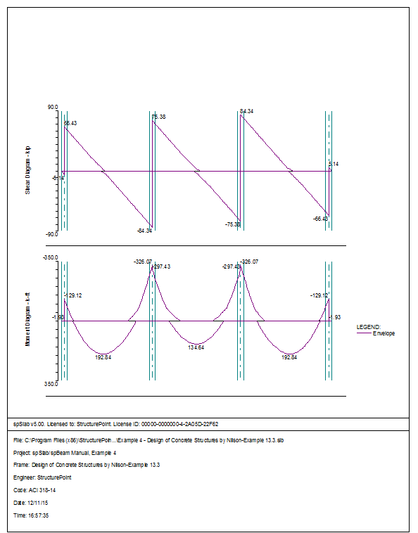
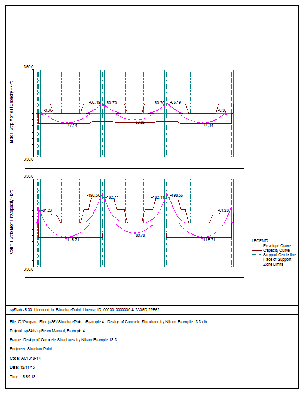
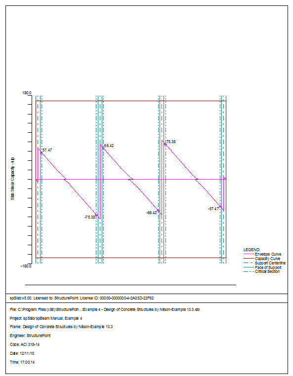
11.To view diagrams, select Loads, Internal Forces, Moment Capacity, Shear Capacity, Deflection, or Reinforcement from the View menu. Right click in any of these diagrams to get new copy, printing, or display options.
12.You may print the results report by using the spReporter module. To print any of the diagrams you selected to view, use the Print Preview command found by right clicking in the diagram’s window. After viewing the results, you may decide to investigate the input beams under the same loads but with a modified reinforcement configuration.
13.From the Input menu, select General Information. In the General Information dialog box change the Run Mode option to Investigation. Do not change any of the other options. Press Ok
14.From the Input menu, select the different commands under Reinforcement Criteria and Reinforcing Bars to modify the reinforcement configuration computed by the program.
15.Repeat steps 10 and subsequent to perform the investigation and view the results.


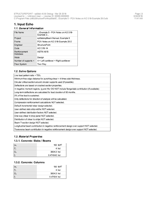
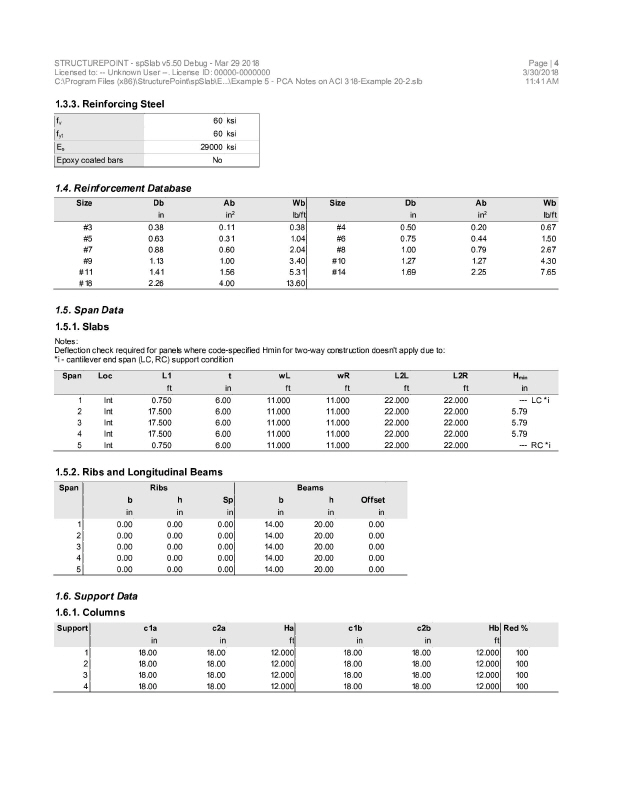
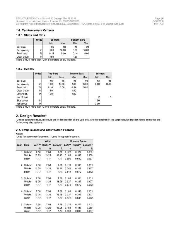
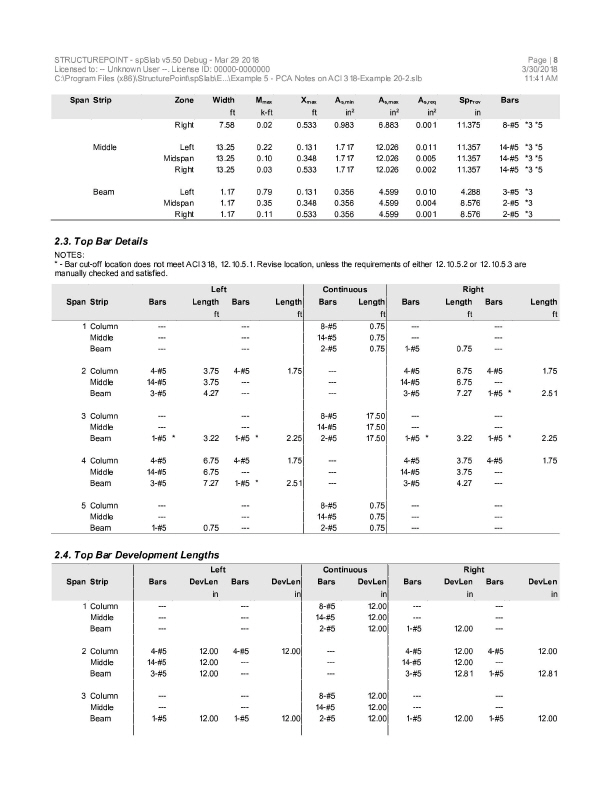
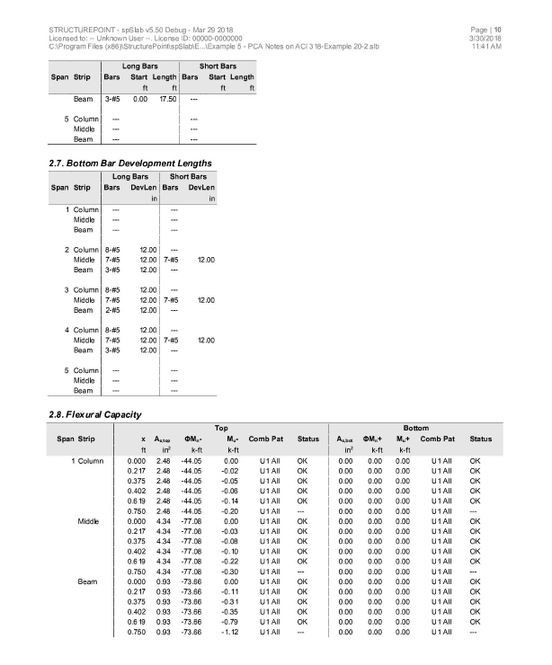
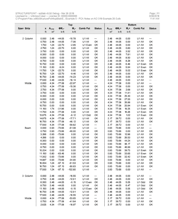
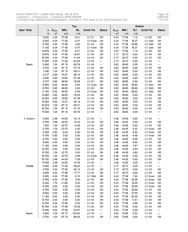
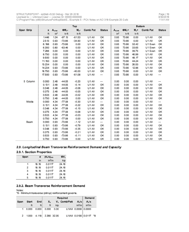
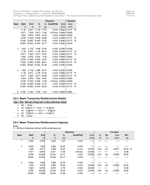
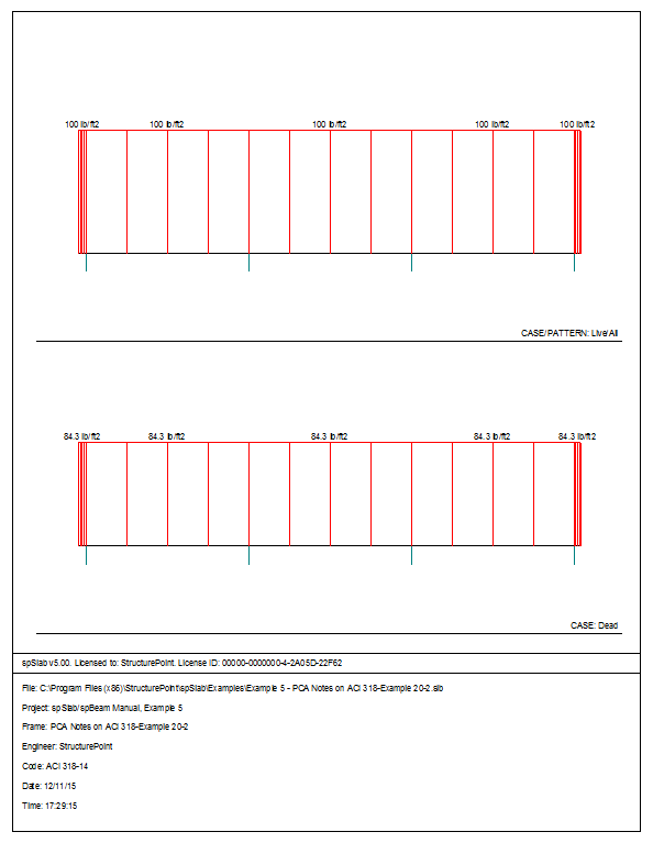
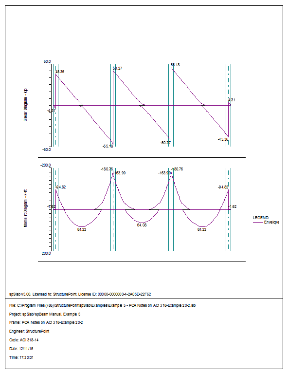
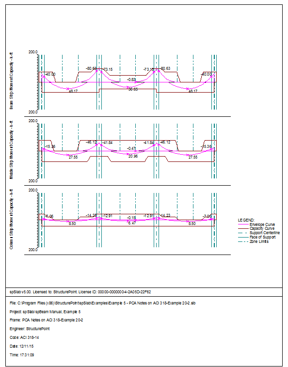
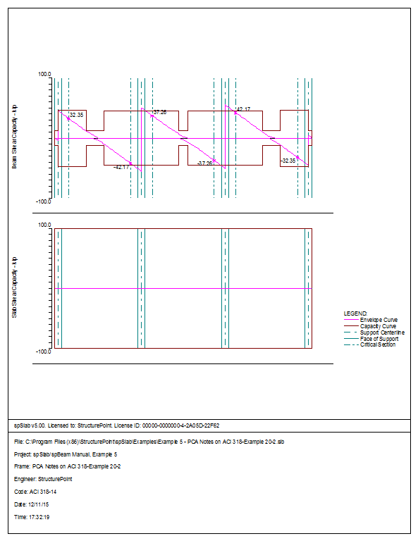
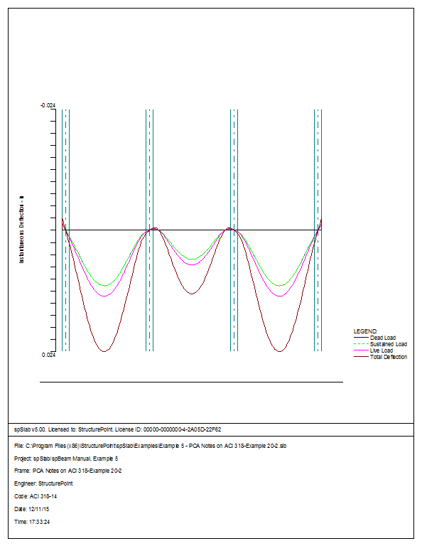
6.5Example 5 Two-way Slab System
Using the Equivalent Frame Method, determine design moments for the slab system in the direction shown, for an intermediate floor. This example refers to Example 20-2 from PCA Notes on ACI 318 Building Code Requirements for Structural Concrete.
Story height = 12 ft
Edge beam dimensions = 14 ´ 27 in.
Interior beam dimensions = 14 ´ 20 in.
Column dimensions = 18 ´ 18 in.
Service live load = 100 psf
Dead load = self weight
f¢c = 4000 psi (for all members), normal weight concrete
fy = 60,000 psi
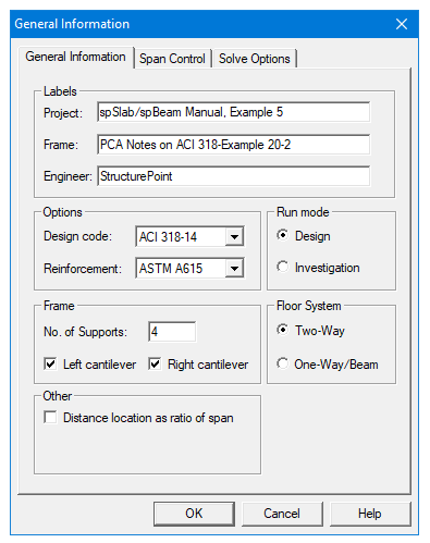
1.From the Input menu, select General Information. A dialog box appears.
–In the Labels section, input the names of the project, frame, and engineer.
–In the Frame section, input 4 for No of supports. . Then, Click the check boxes next to Left Cantilever and Right Cantilever.
–In the Floor System section, click the radial button next to Two-Way.
–Leave all other options in the General Information tab to their default settings of ACI 318-1 design code, ASTM A615 reinforcement, and Design run mode option.
2.Nothing needs to be changed in the Material Properties menu.
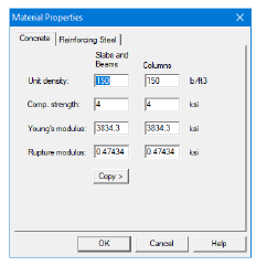
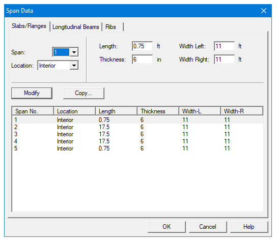
3.From the Input menu, select Spans. A dialog box appears.
–Under the Slabs/Flanges tab, for Span No. 1 input 0.75 for Length, 6 for Thickness, and 11 for Width Left and Width Right. Press Modify.
–Press Copy. Click the check box next to SPAN NO. 5. Press Ok.
–Under the Slabs/Flanges tab, for Span No. 2 input 17.5 for Length, 6 for Thickness, and 11 for Width Left and Width Right. Press Modify.
–Press Copy. Click the check boxes next to Span No. 3 and Span No. 4. Press Ok.
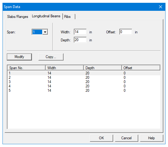
–Select the Longitudinal Beams tab. Input 14 for Width and 20 for Depth. Press Modify.
–Press Copy. Press the Check All button. Press Ok.
–Press Ok again.
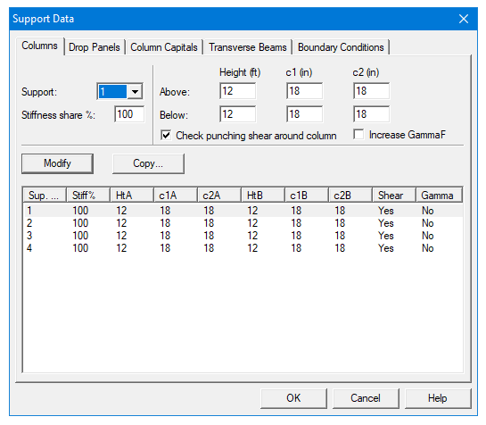
4.From the Input menu, select Supports. A dialog box appears.
–Under the Columns tab, input 12 for the Height in both the Above and Below rows.
–Input 18 for both the c1 and c2 values in both the Above and Below rows. Press Modify.
–Press Copy. Press the Check All button. Press Ok.
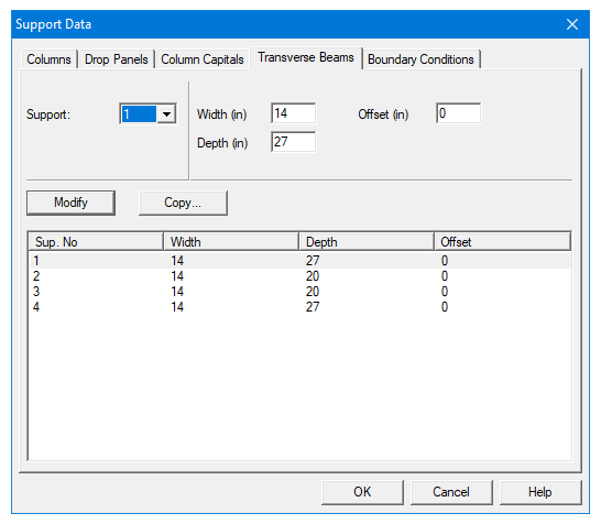
–Under the Transverse Beams tab, input 14 for Width and 27 for Depth. Press Modify.
–Press Copy. Click the check box next to Support 4. Press Ok.
–Use the drop down arrow next to Support to select Support 2.
–Input 14 for Width and 20 for Depth. Press Modify.
–Press Copy. Click the check box next to Support 3 and unclick the check box next to Support 1. Press Ok.
–Press Ok again.
5.Nothing needs to be changed in the Reinforcement Criteria menu.
6.From the Input menu, select Load Cases. A dialog box appears.
–Since the Self weight is to be entered under DEAD Load Label to match the Reference’s input, click on SELF in the Label column on the top of the list of the Load Cases dialog box and press the Delete button.
–Since we are not considering snow loads, click on Snow in the Label column on the list in the bottom half of the Load Cases dialog box and press the Delete button.
–Since we are not considering lateral forces, click on Wind in the Label column on the list in the bottom half of the Load Cases dialog box and press the Delete button.
–Click on EQ in the Label column and press the Delete button. Press Ok.
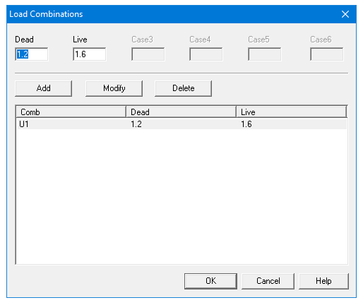
7.From the Input menu, select Load Combinations. A dialog box appears.
–Delete all the load combinations by clicking anywhere on the list in the bottom half of the Load Combinations dialog box and pressing the Delete button. Repeat this procedure until all the load combinations are gone.
–Input 1.2 in the Dead field, and 1.6 in the Live field. Press Add.
–Press Ok.
8.From the Input menu, select Span Loads. A dialog box appears.
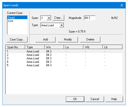
–In the top left corner of the Span Loads dialog box, there is a section called Current Case. Click on DEAD.
–Input 84.3 for Magnitude. Press Add.
–Press Copy. Press the Check All button. Press Ok.
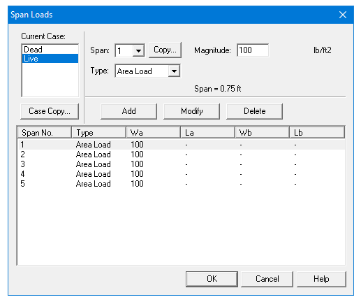
–Then, click on Live in the Current Case section.
–Input 100 for Magnitude. Press Add.
–Press Copy. Press the Check All button. Press Ok.
–Press Ok again.
9.From the Solve menu, select Execute. Press Close.
10.From the Solve menu, select Results.
–Use the explorer to browse through result tables.
–Use the ARROW keys or the mouse wheel to browse through different parts of the table quickly. Press the Close button to close the spRESULTS.
6.5.5Viewing and Printing Results
11.To view diagrams, select Loads, Internal Forces, Moment Capacity, Shear Capacity, Deflection, or Reinforcement from the View menu. Right click in any of these diagrams to get new copy, printing, or display options.
12.You may print the results report by using the spReporter module. To print any of the diagrams you selected to view, use the Print Preview command found by right clicking in the diagram’s window. After viewing the results, you may decide to investigate the input beams under the same loads but with a modified reinforcement configuration.
13.From the Input menu, select General Information. In the General Information dialog box change the Run Mode option to Investigation. Do not change any of the other options. Press Ok
14.From the Input menu, select the different commands under Reinforcement Criteria and Reinforcing Bars to modify the reinforcement configuration computed by the program.
15.Repeat steps 10 and subsequent to perform the investigation and view the results.